 kelvinA
Results
Coaxial8or r0
4-in-1-out Coaxial Hotend
Inspiration and/or examples of working principle
Navigation
The title tag system is explained here, and the table is updated when a change occurs. Notable logs have bold L# text.
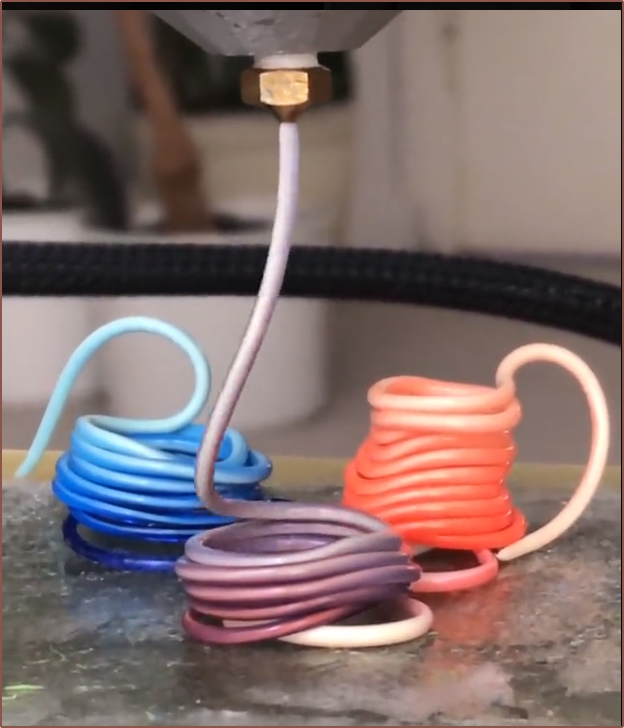
Read more »Full-colour FFF? Multi-materials with unparalleled interlayer bond strength? Abrasives without abrasion?
Already have an account? Log in.
To make the experience fit your profile, pick a username and tell us what interests you.
The title tag system is explained here, and the table is updated when a change occurs. Notable logs have bold L# text.
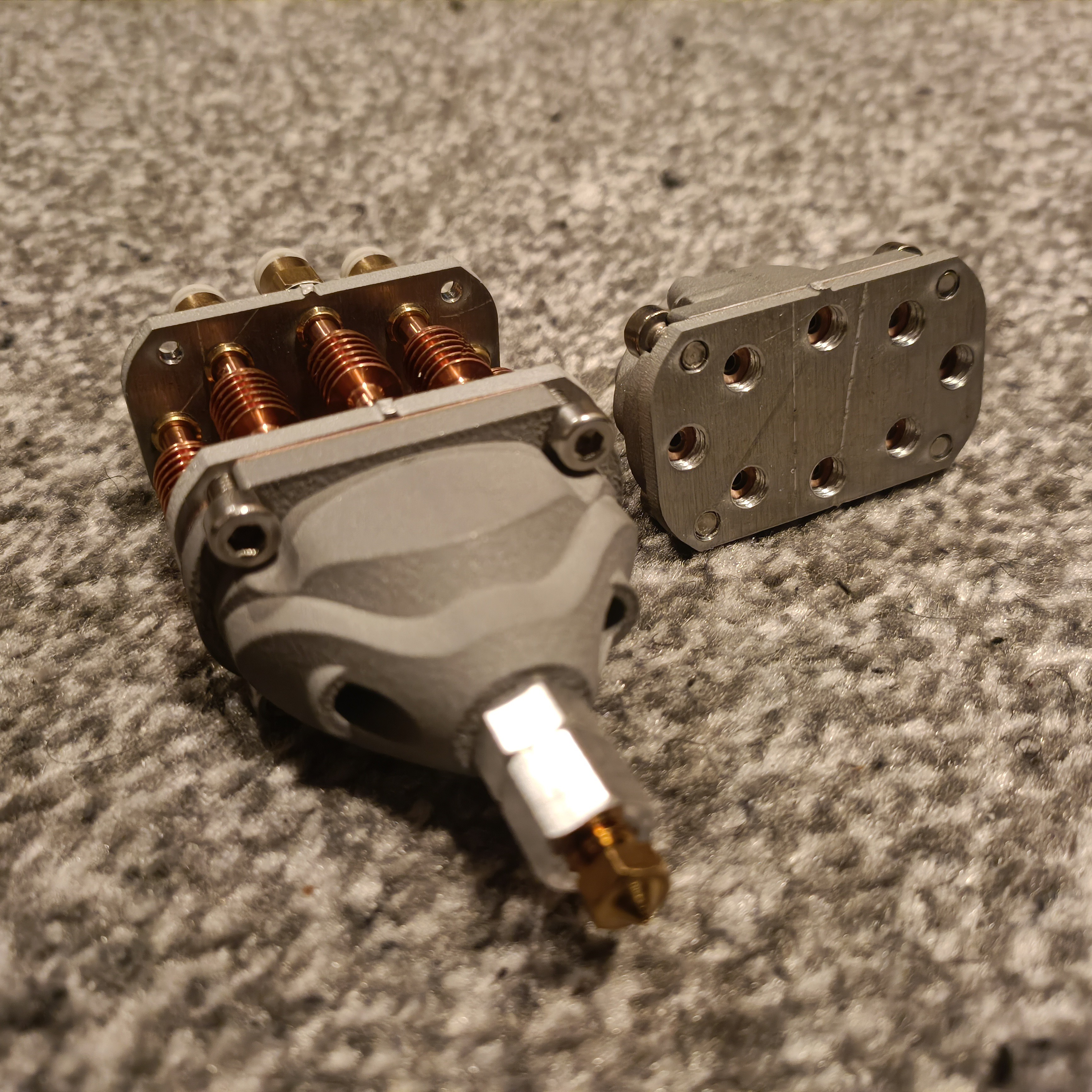
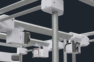
Read more »I envision a merge between the small heatsinks and the Bambu Lab heatblocks (see below) as a way to be able to turn on and off different inputs. Something like 10 watts should be enough.
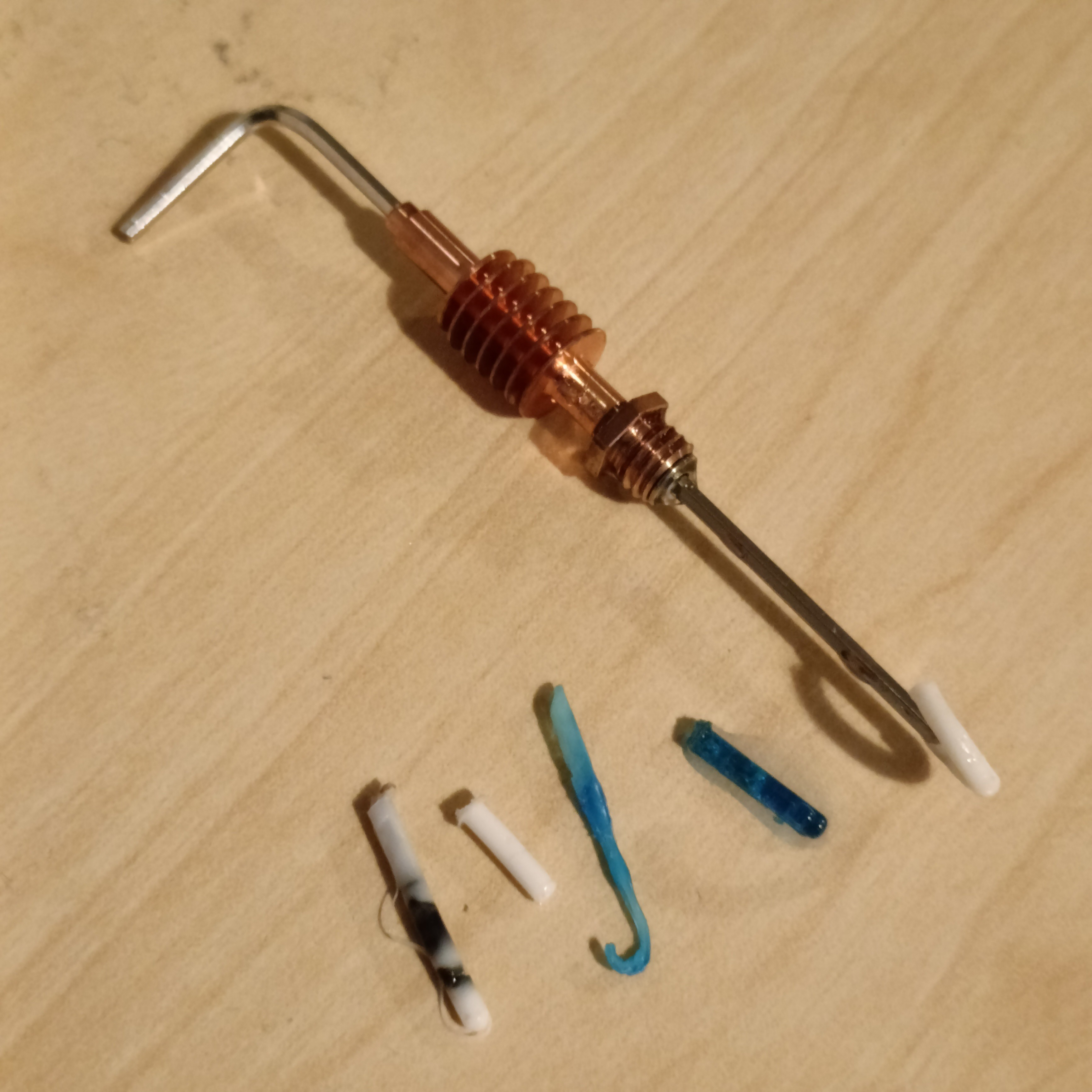
This comes after I spent some time yesterday putting the heatsinks in fresh-out-of-the-kettle water to be able to get the PETG out of them:
I believe that the temperature doesn't need to be too precise, and that it might even be sufficient to simply connect the heater to a thermal fuse to have both quicker heatup times and a bang-bang temperature control. An example could be a 200C thermal fuse that resets after it cools to 170C.
Even this might not be needed, as if I recall correctly, ceramic heaters naturally have a temperature limit due to increasing resistance at higher temperatures. In that way, it may be possible to design a heater that quickly reaches equilibrium at 200 - 210C, which is the maximum temperature Deckingham needed for the majority of his material tests.
In this way, only 9 wires would be needed to implement this, there would be no moving parts, and the potential for unused channels being clogged would be minimised.
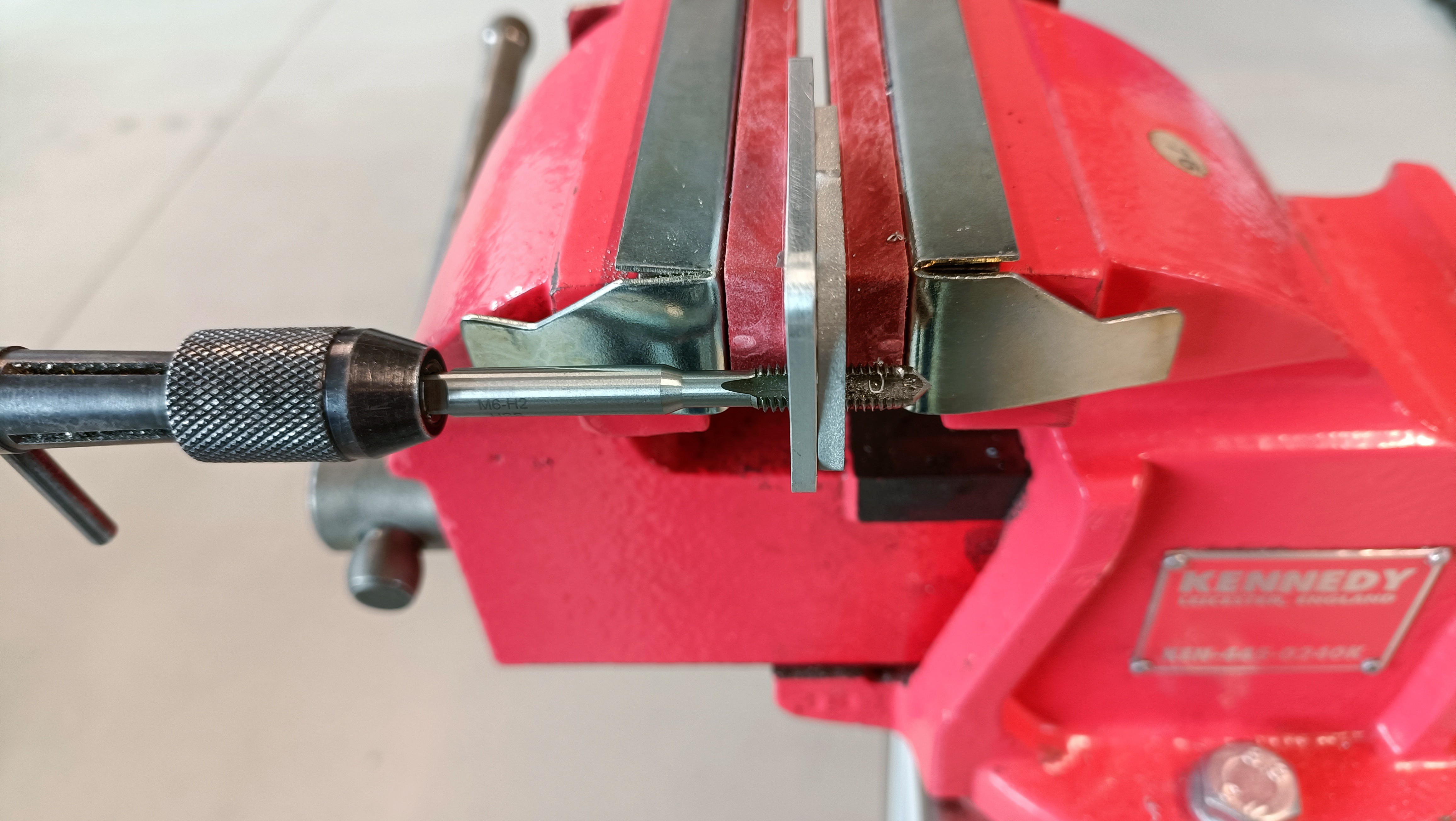
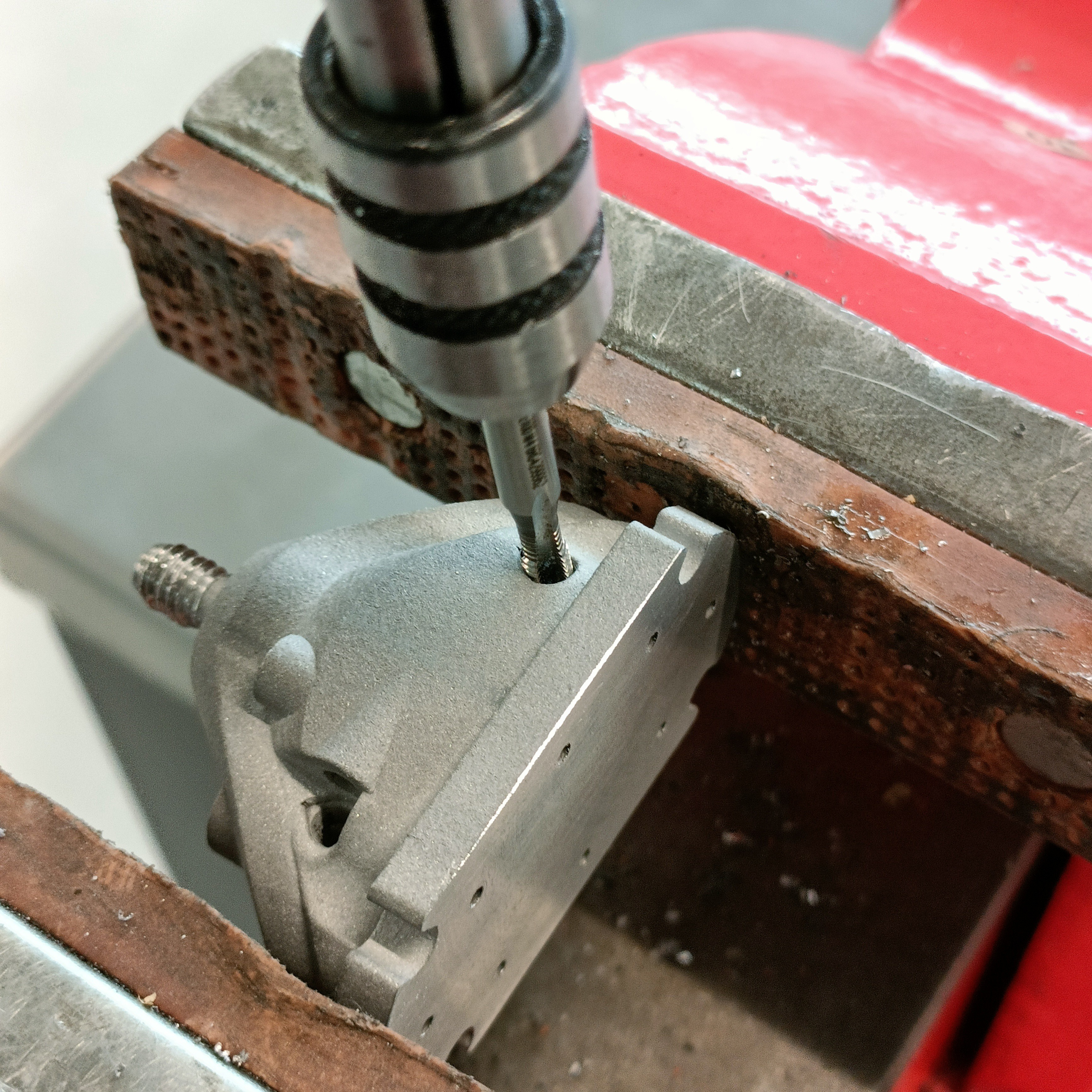
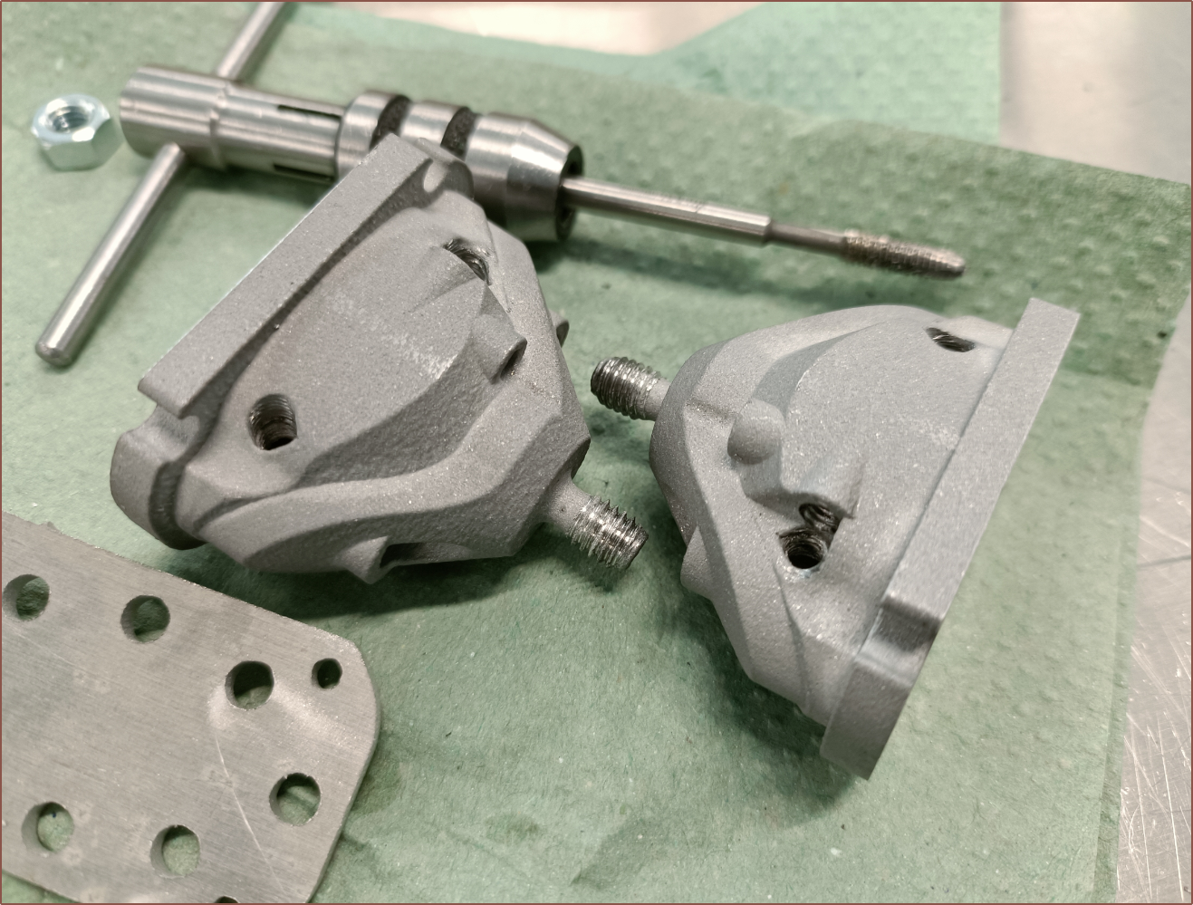
I needed to go back to tap the thermistor thread in one of the Coaxial8ors and, while I was doing that, I thought "I just need a pilot thread to get started and I can be on my way", referencing to tapping the plates. I soon had the idea to print such a jig, but first I tested the idea out with an M6 bolt and learned that I'd need to consider how to keep it in place.
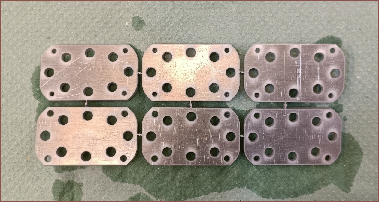
Me1: If only I had a plate with a bunch of starter threads. Then I could put them both in a vice.
Me2: We have plates with starter threads at home.
The plates with starter threads at home:
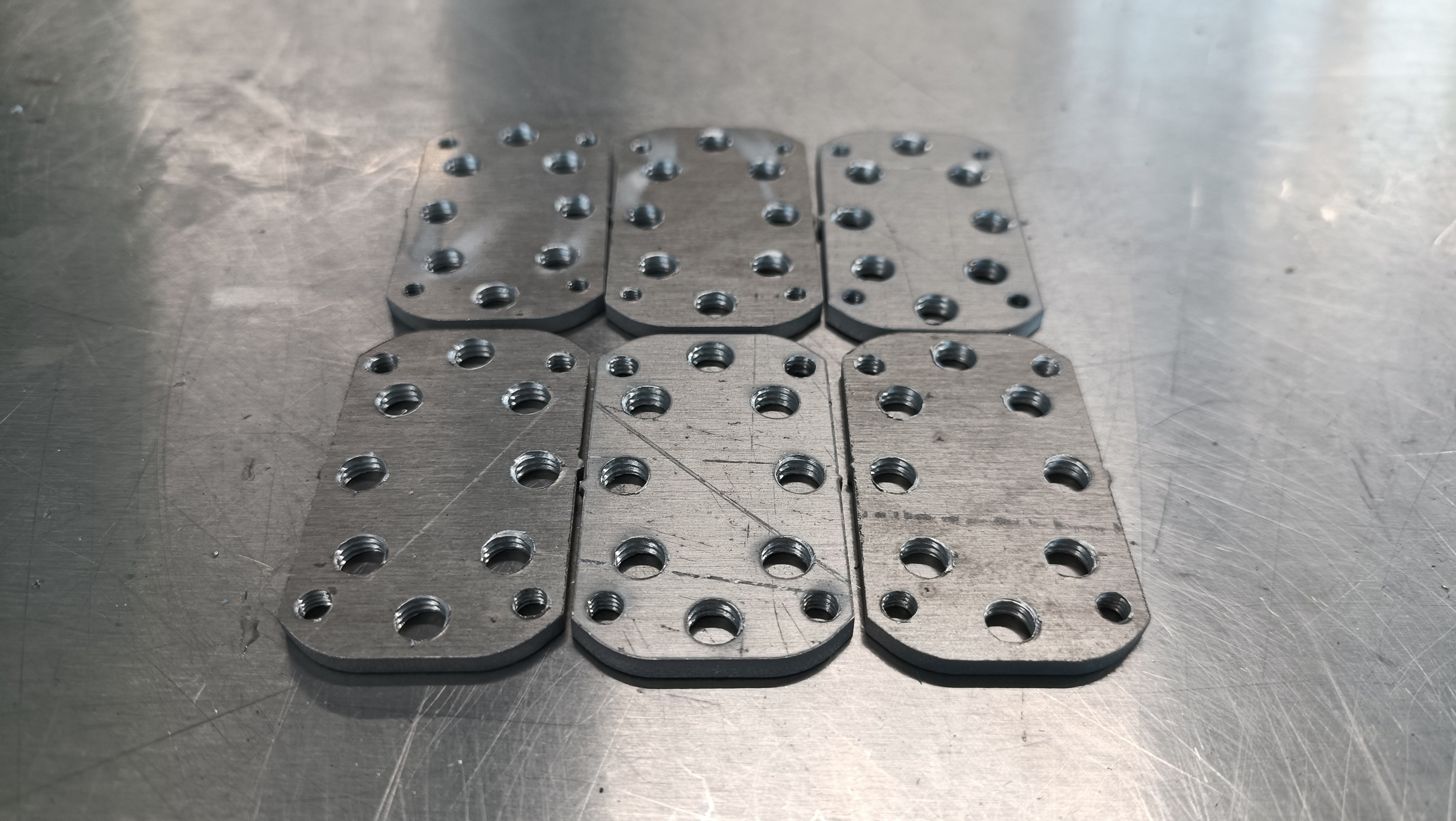
Then I asked for some new plates to be cut, where the holes in the CAD were offset by 0.05 before being exported to .DXF for the waterjet:
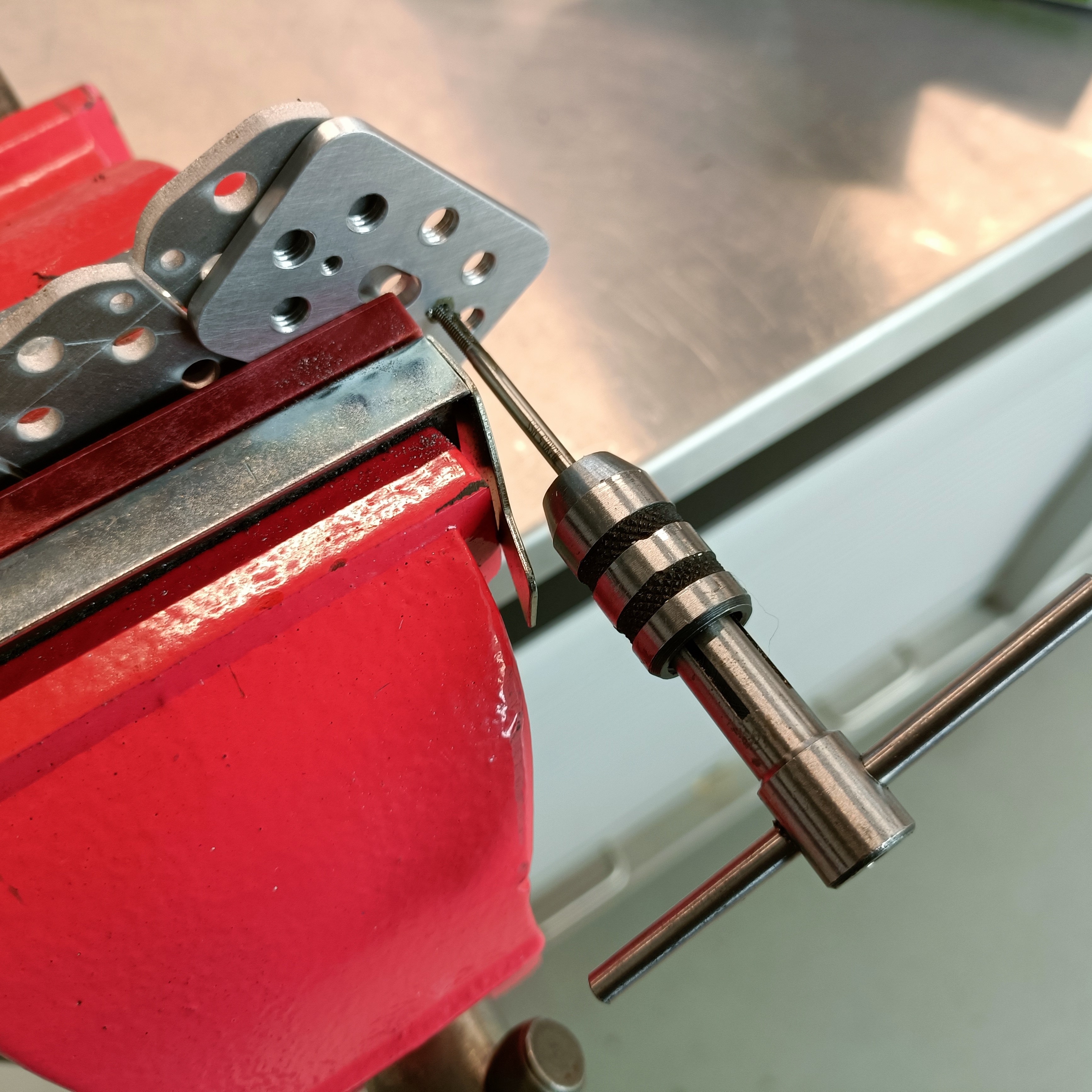
I started off with the M3, and seeing that worked, tried a pilot M6 which seemed to work too. Thus, I switched back to the M3 tap, broke off a plate and threaded all the M3 holes on the new coupler plate.
I started the threads using the old coupler plate, then went back to finish them:
This plan all changed from the M4 tap, where the starting tap doesn't actually finish the threads like the M3 one. Only the finishing tap cuts the threads fully. I couldn't even properly thread in the finishing tap into the starter threads, so I instead decided to just use the finishing tap and fully cut the threads in one pass.
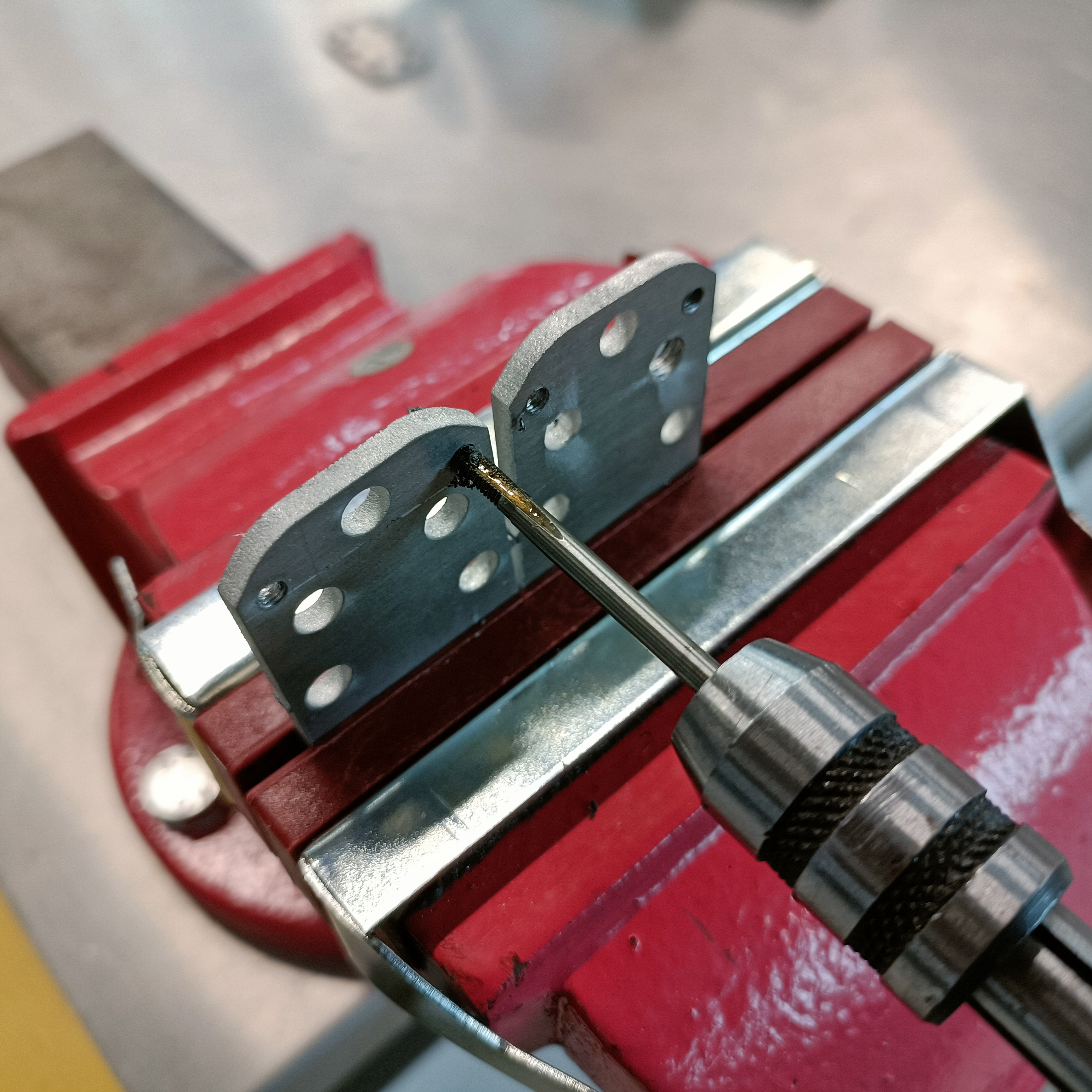
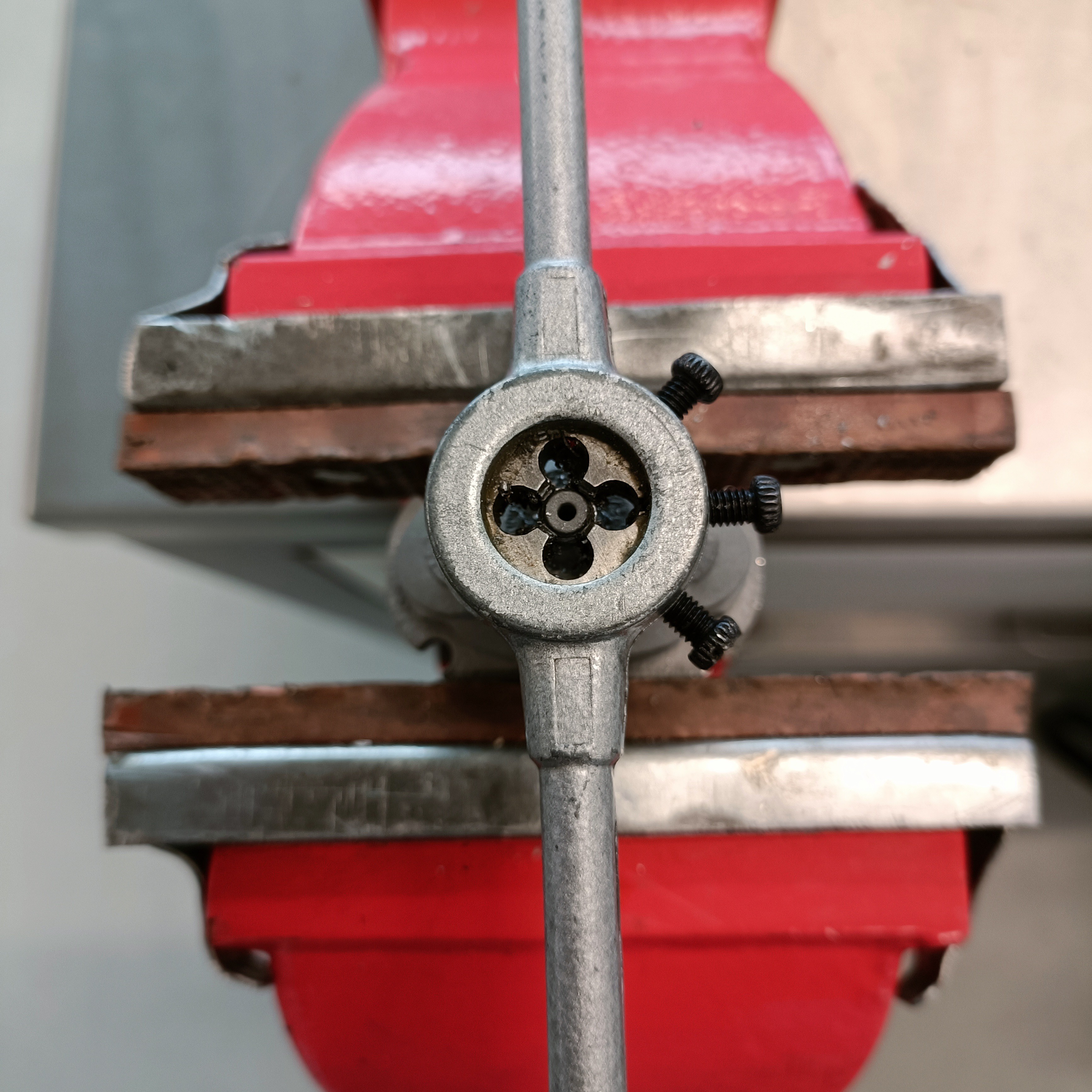
By the time I got to the all-important M6 threads, I had a strategy:
It took me 35 mins to thread the M6es of 2 plates. I think I switched to a new cloner starter tap every 12 or so threads to make sure that the tap was still going in straight.
This is the result:
Surely there's probably an actual specific plate that allows one to hand tap perfectly straight, but I don't know what it's called (or if it even exists).
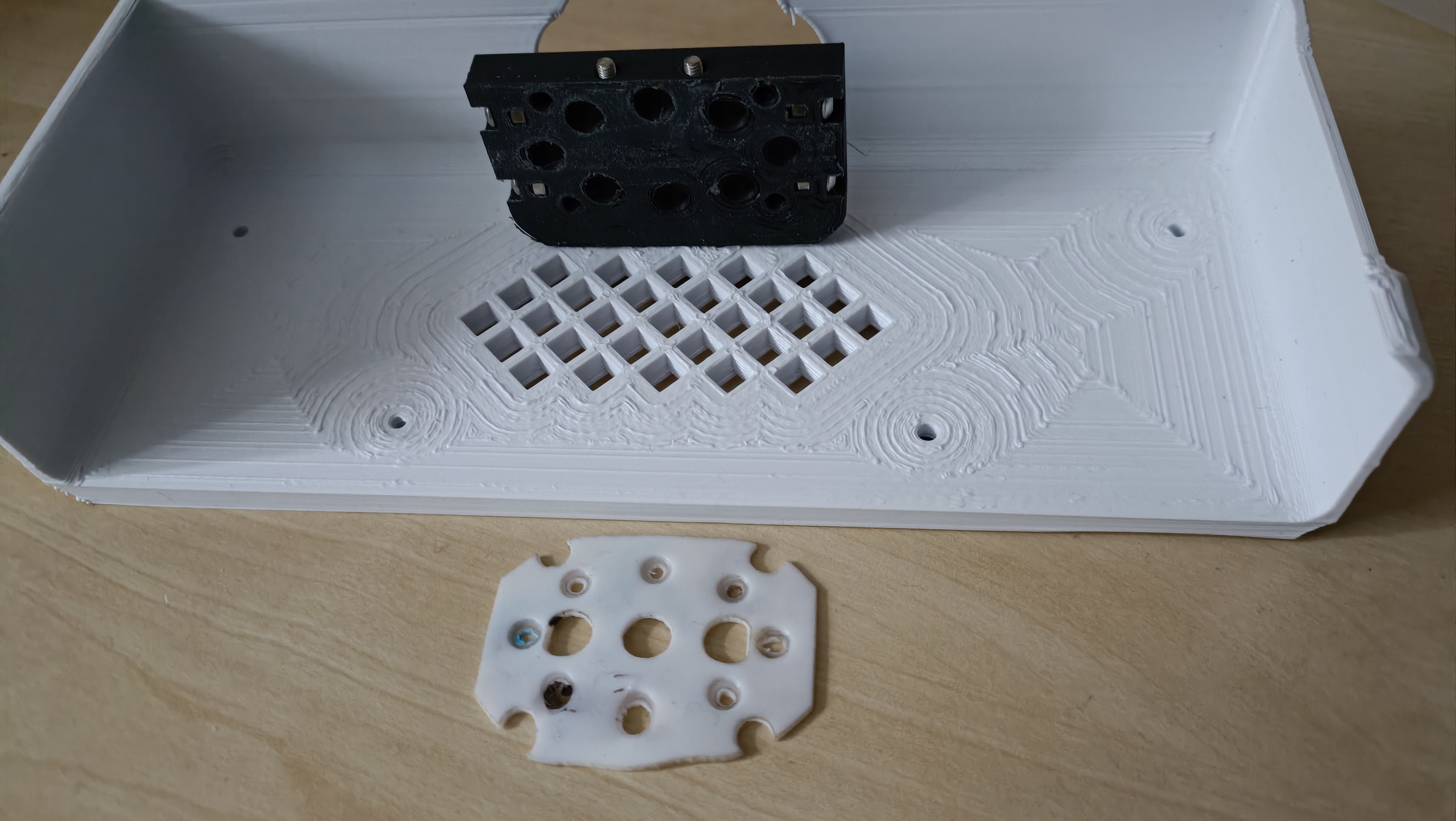
In other news, I also printed the new holder+cover, and saw that the PTFE gasket actually got squashed thin from the top side:
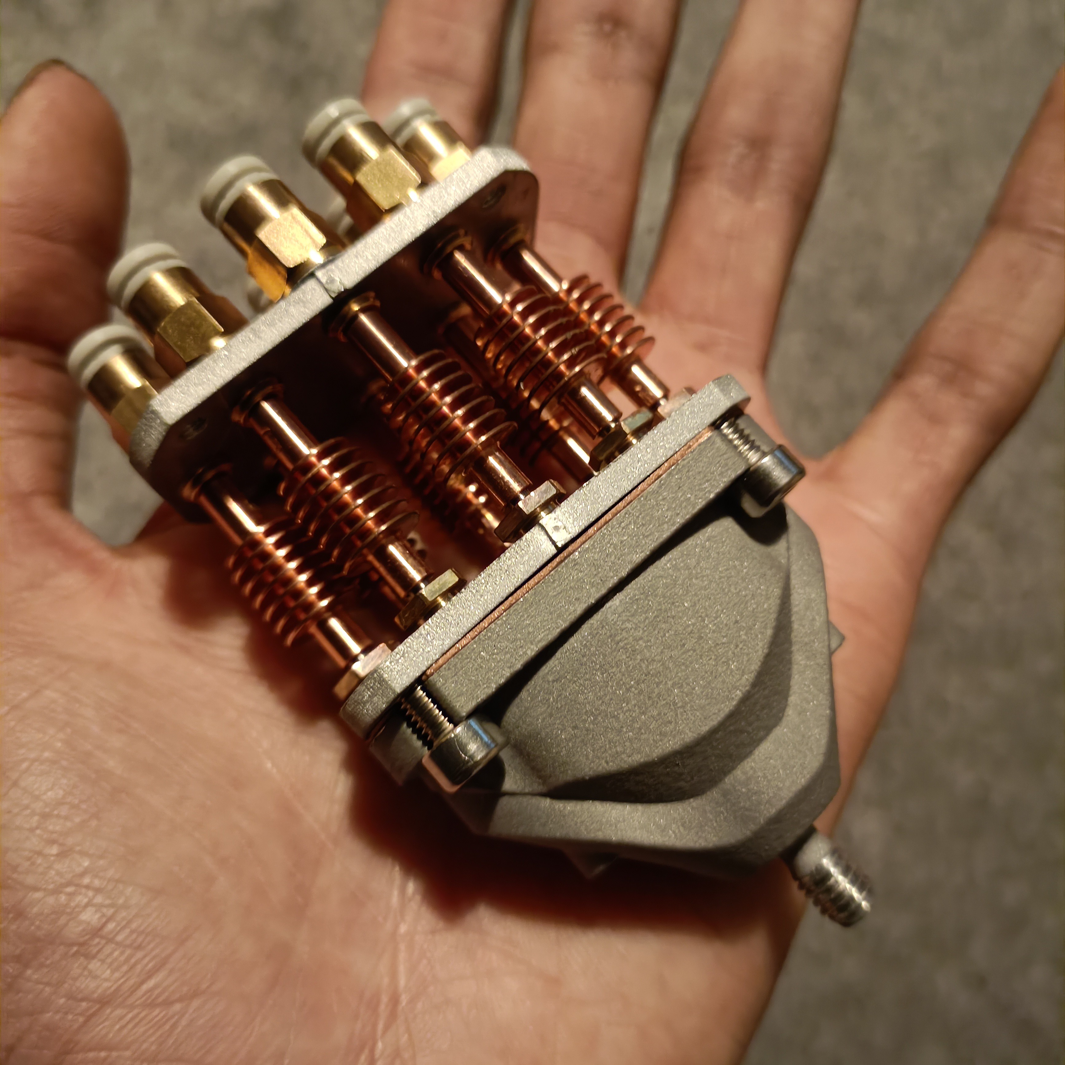
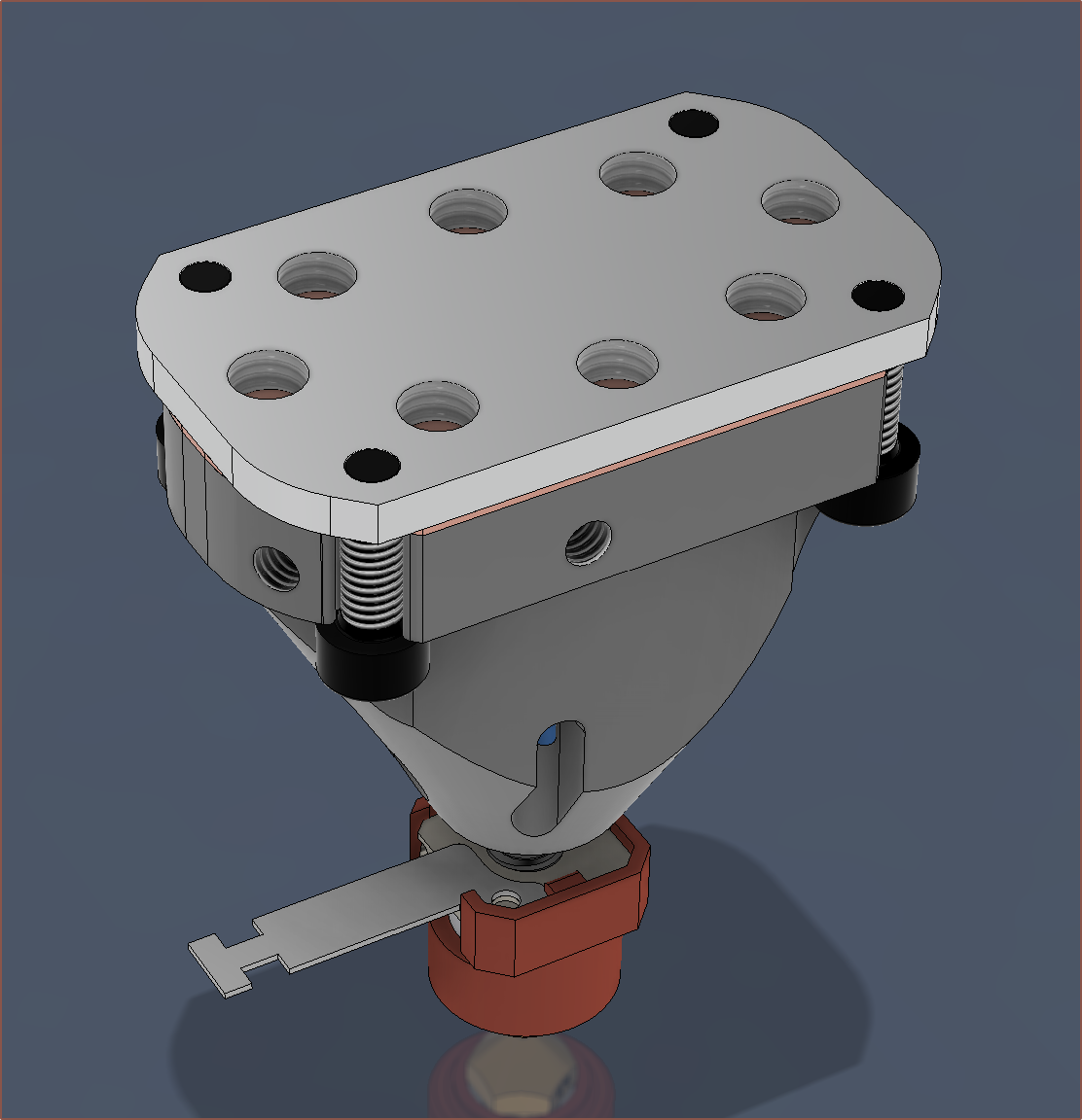
[May 22] It all goes together, so this strategy seems to work at the moment:


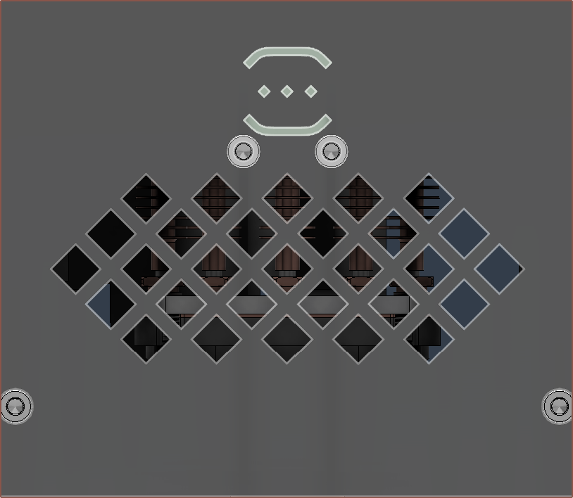
I've gone through and updated the printed files (and the render LEDs to better represent what this hotend is actually doing).
I have changed the grill so that it's easier to see if there's a leak happening on the main gasket. Since this makes the cover look top-heavy, I've moved my logo to the top (which resembles a spool on bearings).
In other news, the grub screw for the thermistor successfully works on one of the two Coaxial8ors so I'm going to need to re-tap the other one.
The machinist technicians just happen to be quite busy at the moment, so I only asked them to mill the top faces.
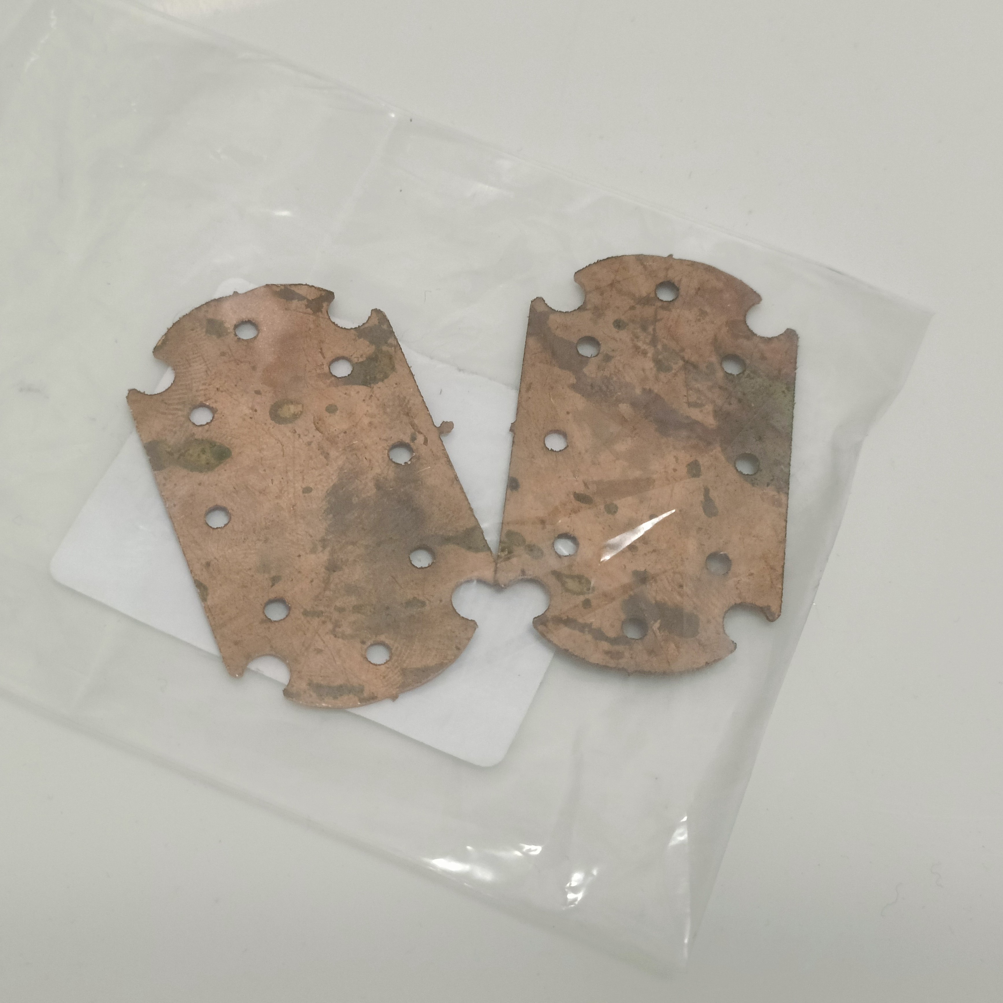
Then I went to the waterjet technicians to ask for the flat parts such as the clamp plate. They just happened to have a small piece of 0.65mm copper that was large enough for 2 gaskets:
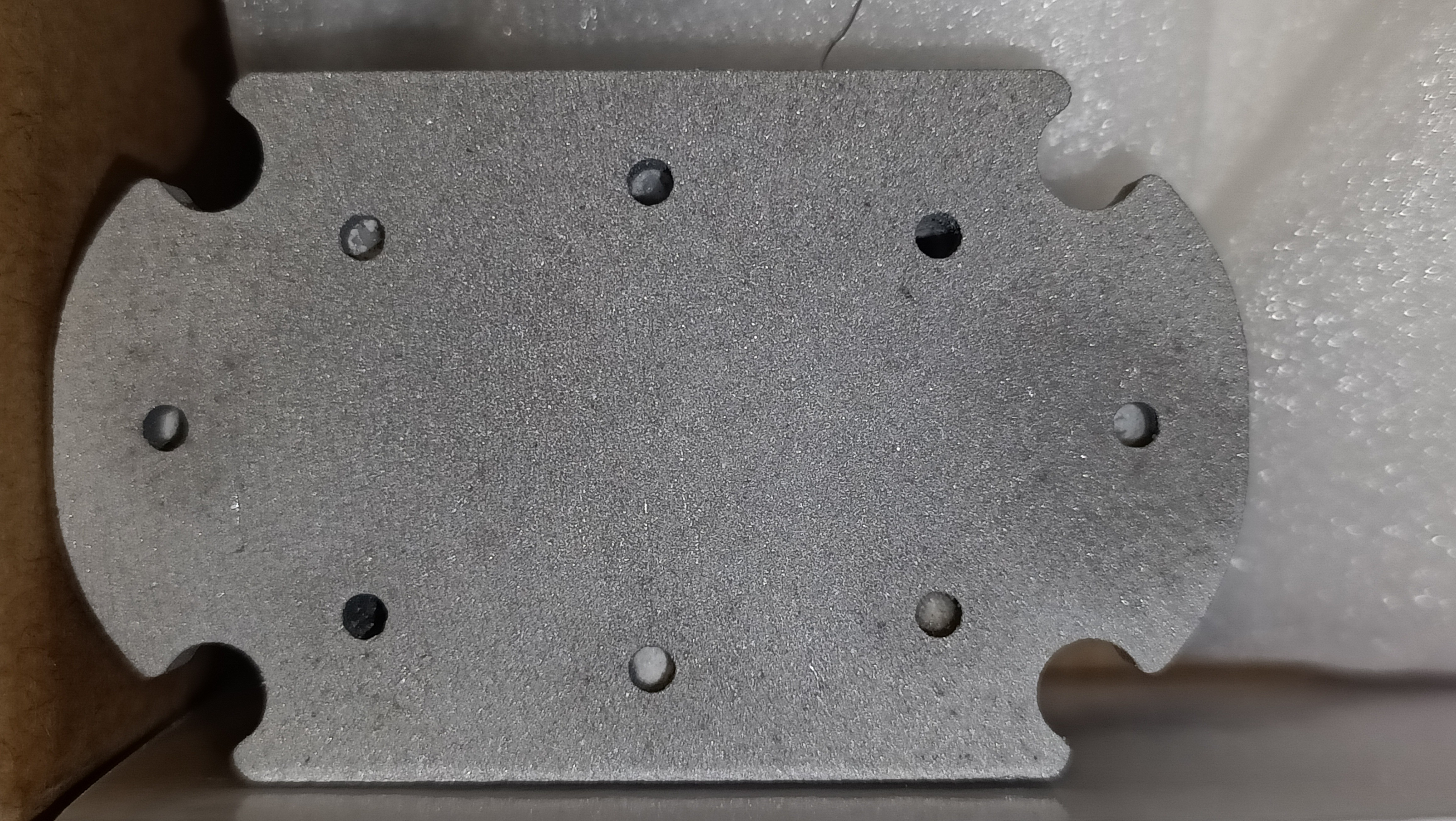
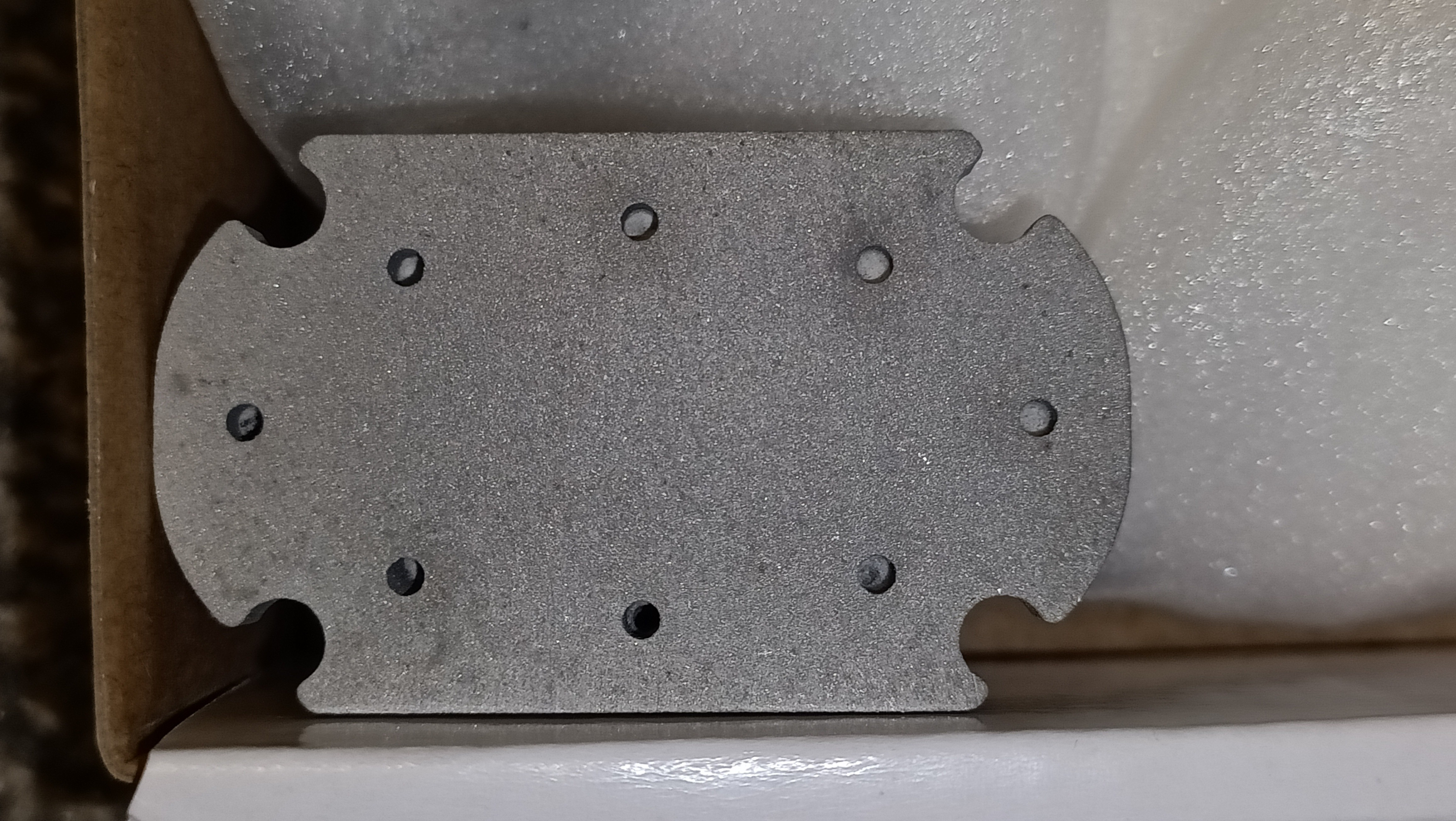
I'm thinking that I should've just left the sizing as is, because the taper through 3mm aluminium is very minor but now the holes are too small to just tap directly. I'm likely going to just wait either until the techs have time or I print a jig or something like using a pillar drill, as I don't think I'd ever get all 32 M6 threads tapped perpendicular to their faces. Worst case is just ordering more parts from PCBWay.
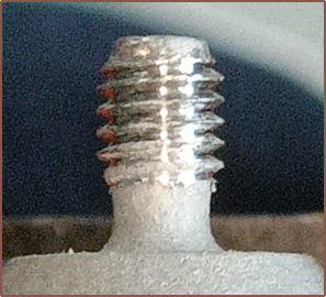
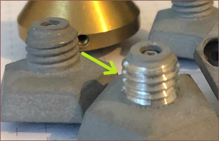
The M6 threads took a bit of careful consideration to get started, but I only got the threads to bite in one location meaning that it likely was going down the printed threads.
Lastly, I lined up my eye directly over each of the M4 holes to tap and used a fiducial marker like a shadow or tip of my foot to mark the horizontal line (to account for my head slightly drifting) and then placed the tap directly over so that I could account for any 2D angle errors.
So far, it feels like the 2-for-1 offer is paying off, such as the confidence / peace of mind of knowing that I've got a second life if things go pear-shaped. I still haven't dealt with the powder inside them though.
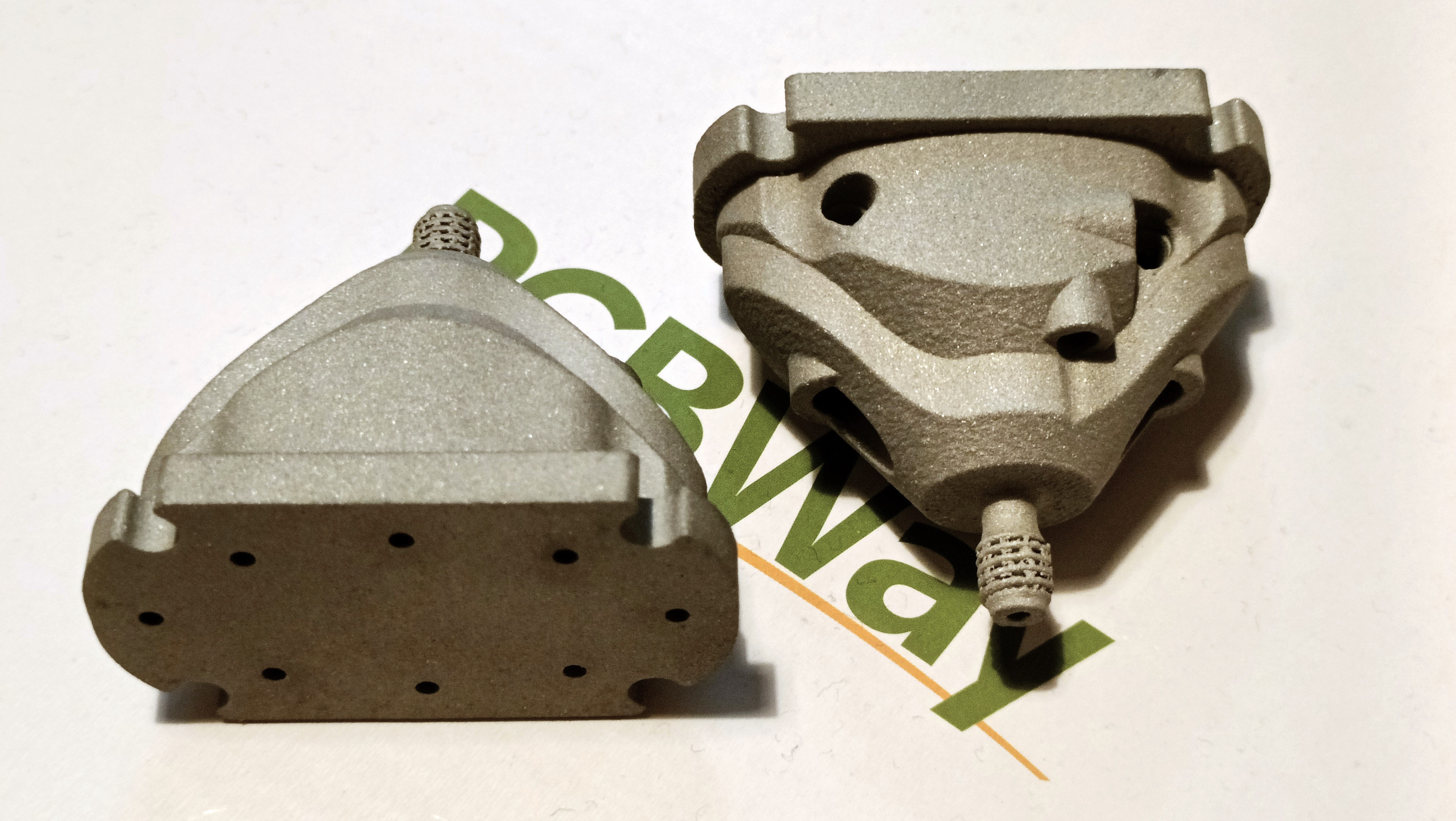
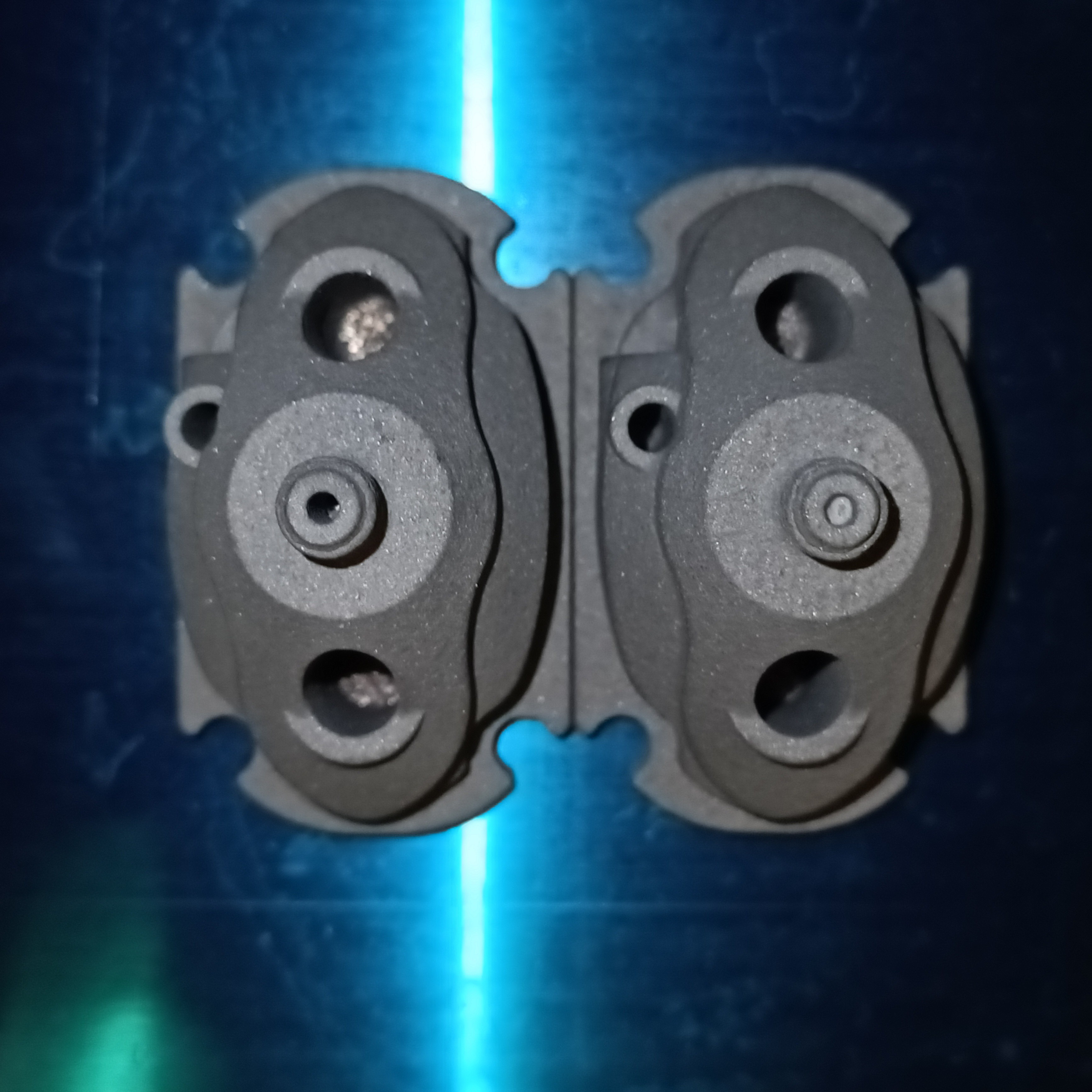
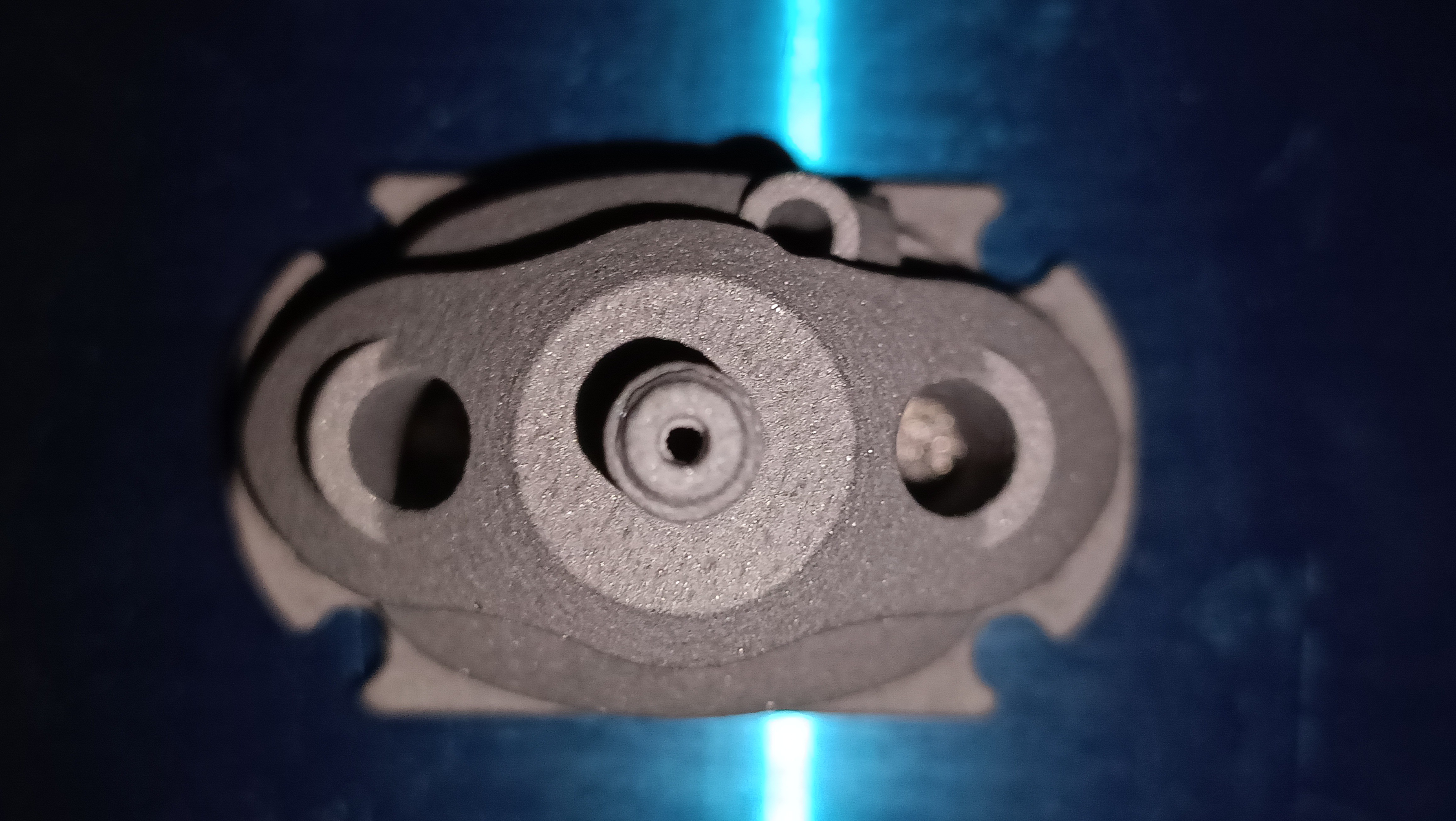
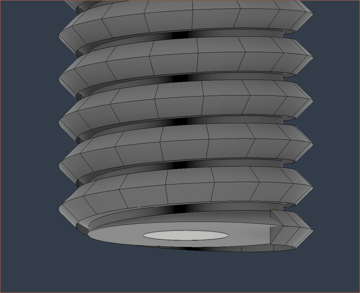
The prints have finally come in and they look as expected (because I had stared at the CAD model for hours making sure everything was right) and the dimensions are good (1.75mm input holes, even less warping than the r0 print, cartridges slide in nicely), but there's a problem:
As you can see, both prints seem to be like completely blocked. As you might be able to see in the second image, I don't think they're "welded shut" or anything, because poking with a toothpick has put some indentation in the lower right diagonal one. One of the prints is 53.2g and the other 52.7g, so it seems that the quantity of powder in them are different. At least I've got 2 so I know it's not a one-off.
Not sure how best to proceed. The channels have been modelled larger and shorter than Revision0 and yet powder has been left in?
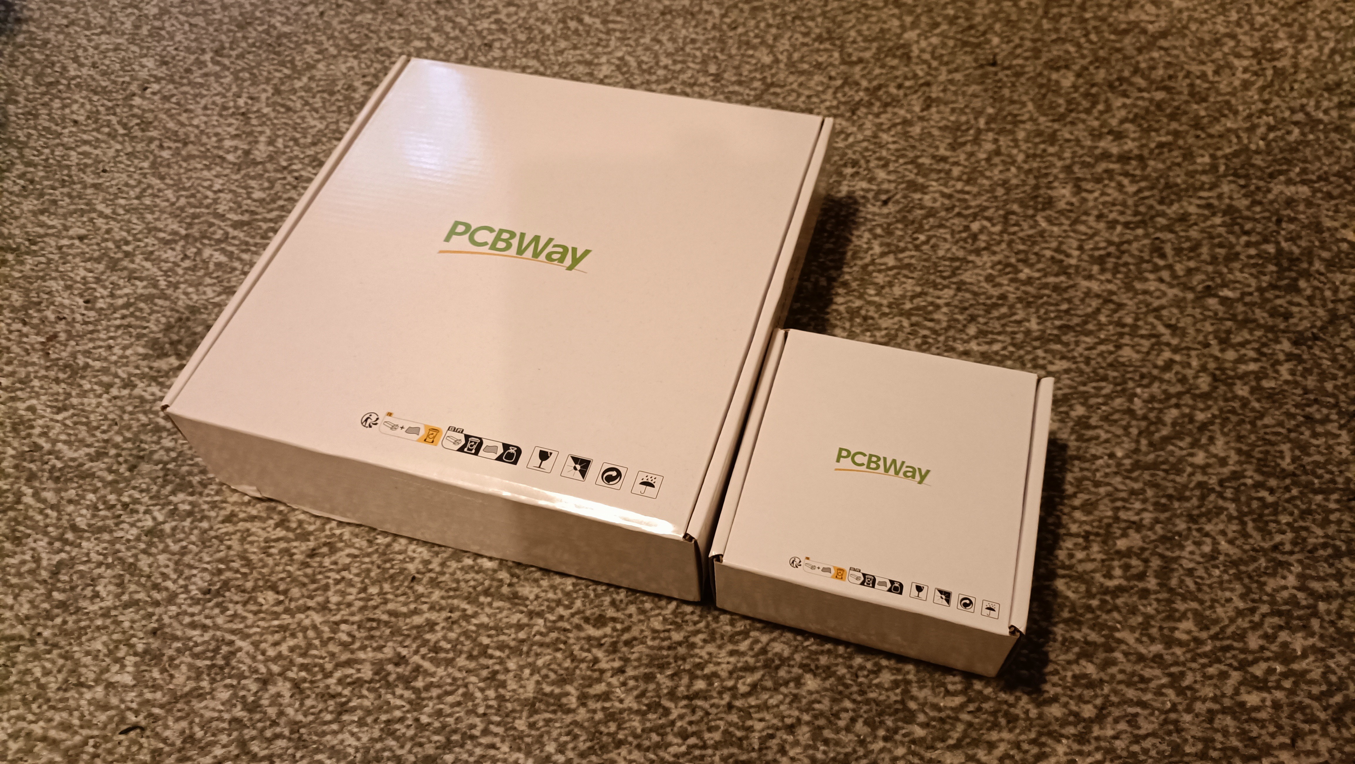
In related news, the box these double c8ors came in was half the dimensions in XY and ever so slightly shorter in Z, suggesting that perhaps the Coaxial8or r0 was just a tad too thick for the smaller box and that's why its shipping was double.
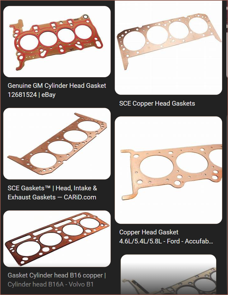
I've also remembered that I should be looking for a gasket material, and was considering brass when I was searching for a copper sheet, but copper gaskets are a real thing (unlike brass it seems):
According to this article, copper was actually "one of the very first materials that was used in the gasket industry".
After some messages between Me <--> Service Rep <--> Engineer, the quoted prices were $38.32 for 1pcs and $73.43 for 2pcs of the aluminium 3D print from PCBWay. The shipping cost hasn't changed at all, suggesting that the c8or r0 must have been just a bit too large and the system bumped it up to a bigger-package charge.
Now it seems that all my "sweat equity" into shavings has synthesised into savings, as I can now buy 2 c8or r1's for about $2 more than a single c8or r0.
In British Pounds, my cost for this specific order is approximately £64. 2^1 pcs of 2^3-channel heatblocks costing £2^6... what's the 2^10 going to be?
Because I was trying to find more information about Construct3D's custom heatblock design that is targetting 200mm^3/s, I started listening to a podcast and one of the things that Jacob mentioned was "intent", describing how the quality of his Minecraft server building designs had much more quality when he had to struggle in Survival Mode to get every block, compared to Creative Mode when he has unlimited everything, and he subsequently brought this idea of intent over to his 3D printer design methodology. Now that I've got a new heatblock design and every millimetre of it has been questioned multiple times, I've been thinking of the similarities to Jacob's talk of intent.
Firstly, some quick changes that have happened in the design:
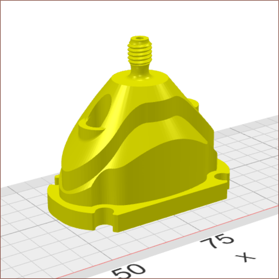
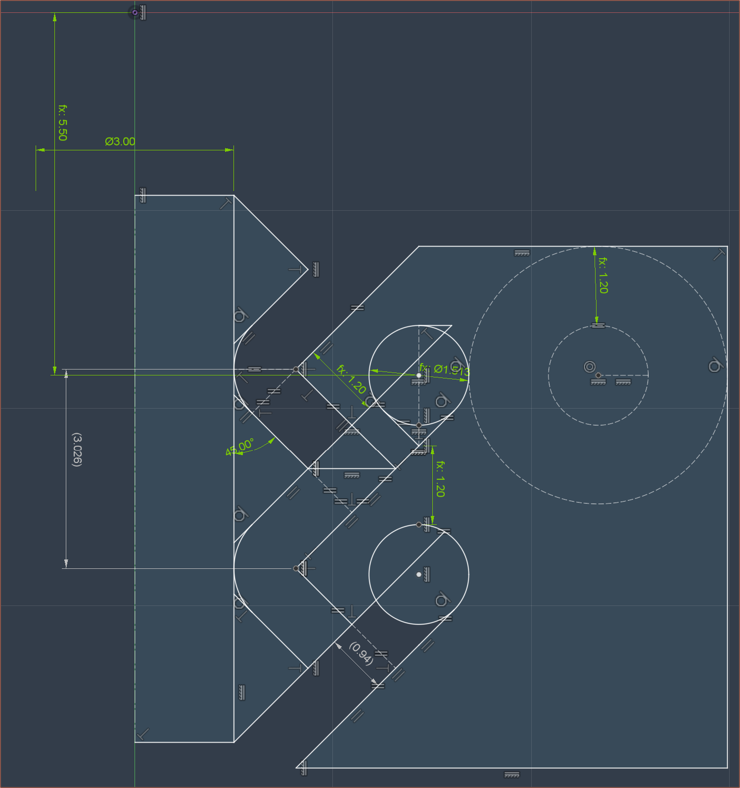
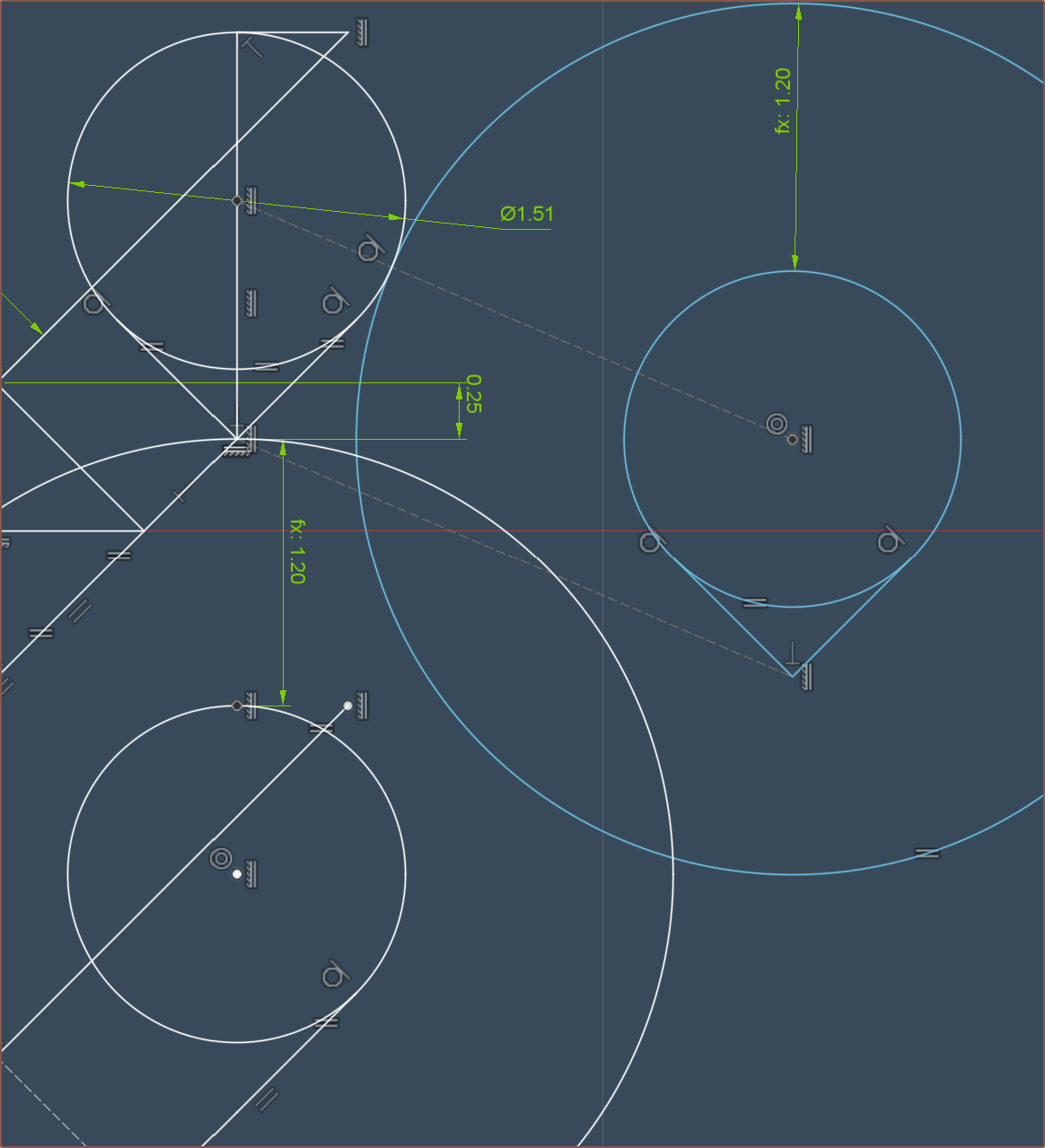
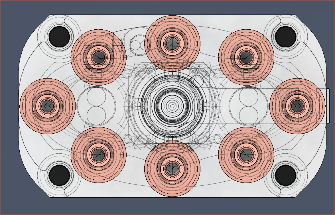
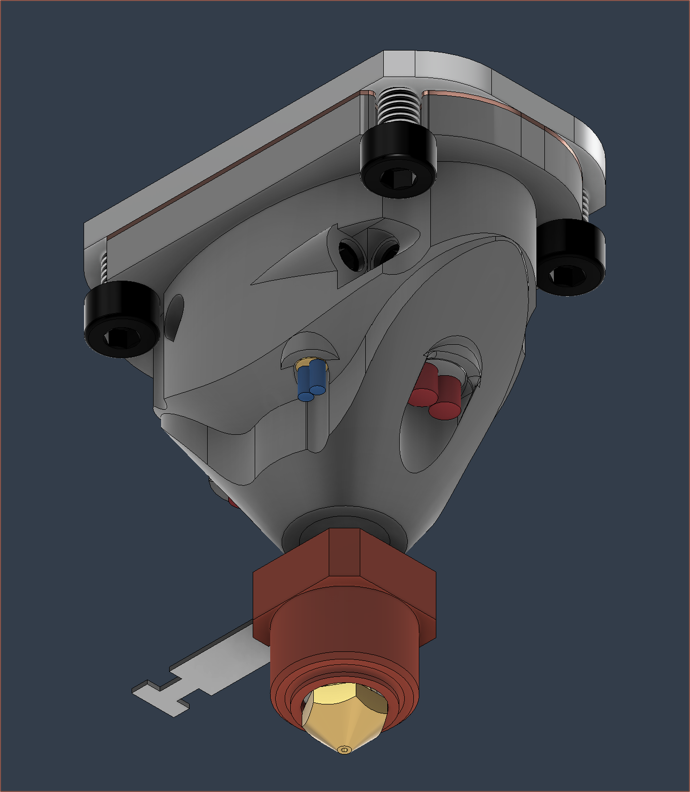
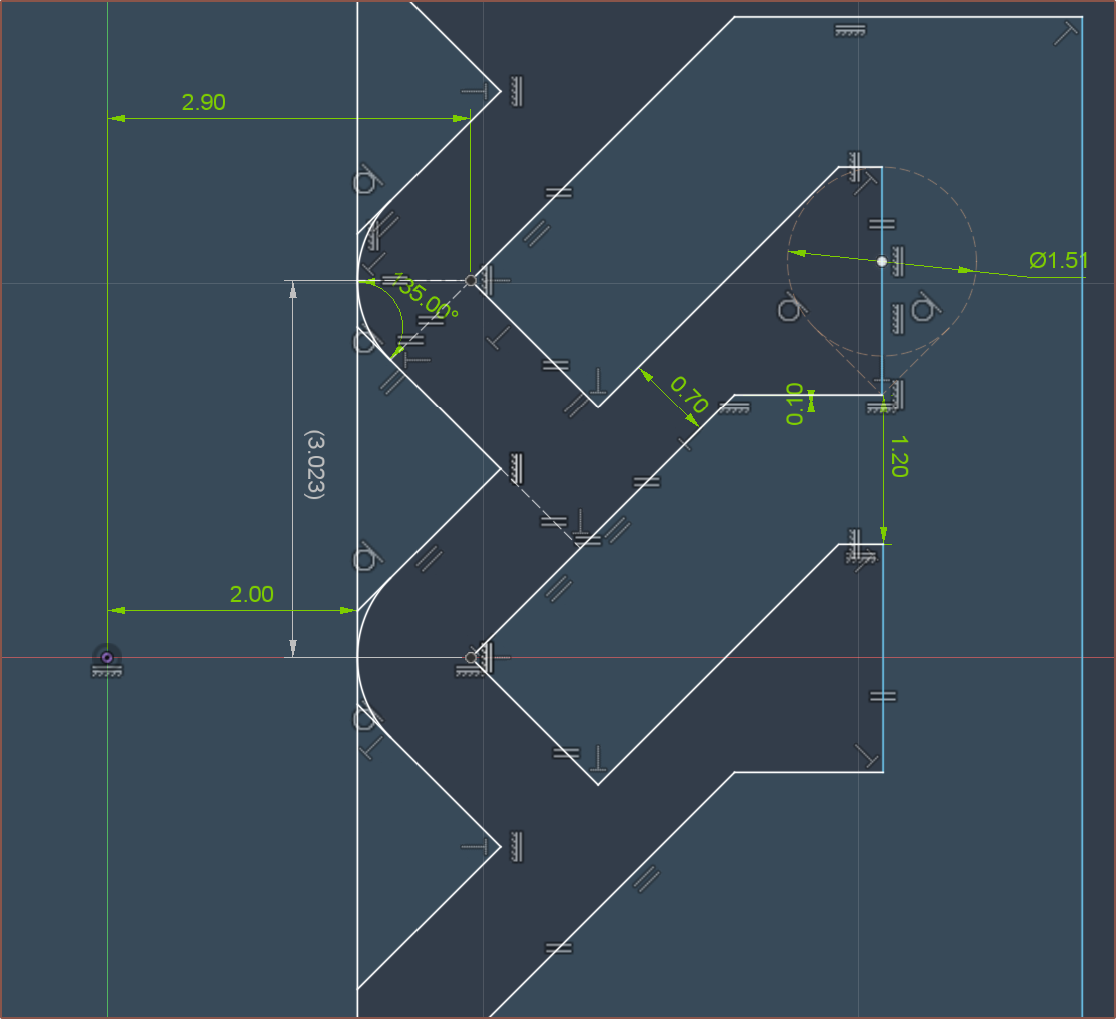
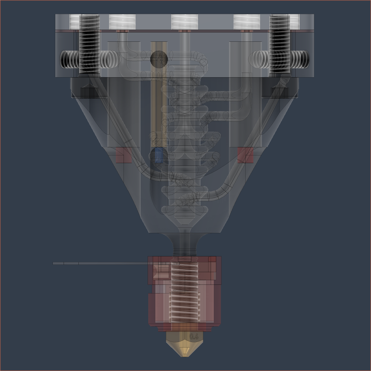
The main profile is shown below:
For weeks, I've been wondering if I should change the 0.95mm spacing, but I felt that I didn't want to even change it by more than +/- 0.05mm so I left it. Well now the geometric laws have spoken, and by ensuring a minimum wall thickness of 1.2mm, the spacing is precisely 0.94mm.
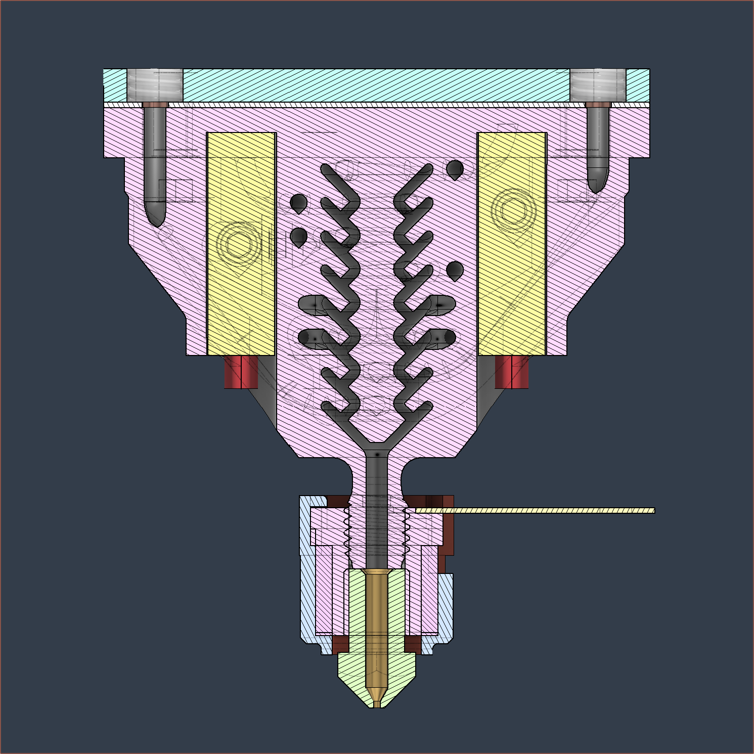
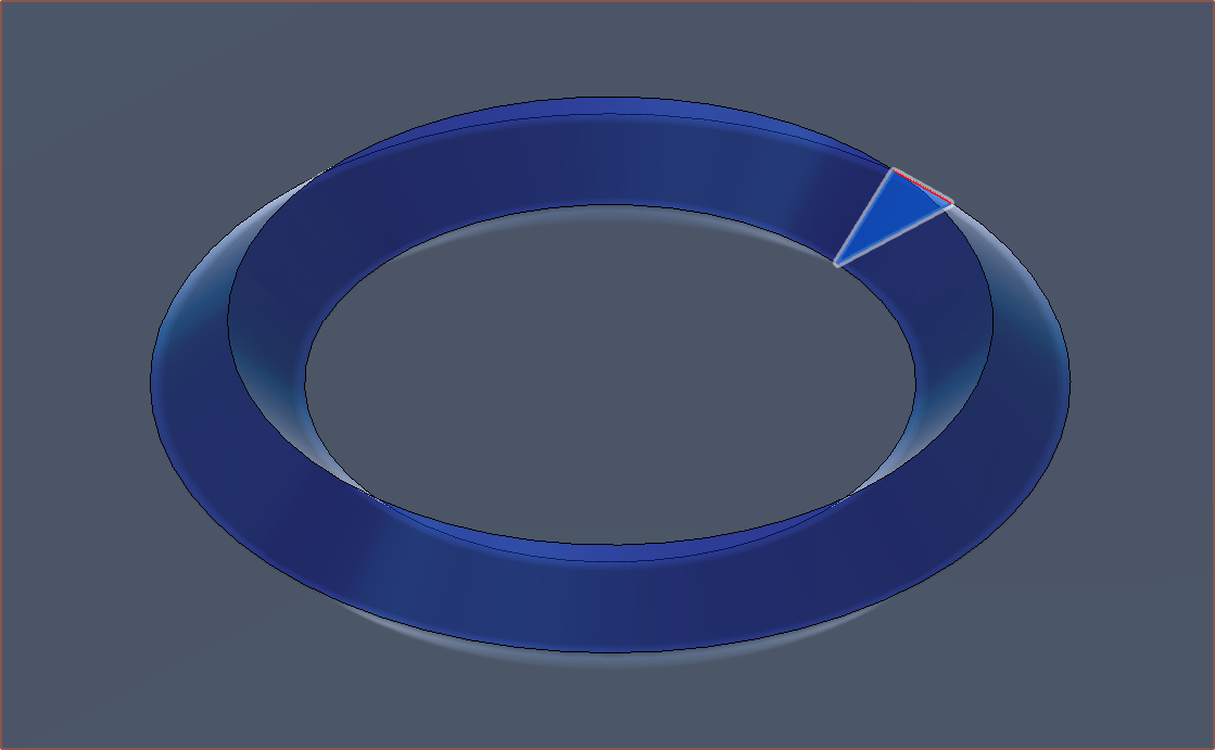
Additionally, the centre pillar now has a much more active role in forming the extrudate instead of being there just because I hope it has a positive effect. As the fluid inside the heatblock is incompressible, the idea is that a push/pull of material will move this 3D revolve of the triangle between the 2 inputs:
The volume of this is 9.118mm^3, and the push/pull length can be found as follows:
( 2 * [purge volume] / ( pi * [filament diameter]^2)
( 2 * 9.188 / (pi * 1.75^2) )
= 1.91mm
I had set my push/pull length for the c8or r0 to be 1.8mm, so I'm doing great on these guestimates.
I'm hoping that this new geometry both gives more time for the cone-ring-CSA to equalise in pressure, reduce the diffusion-area between different materials and make the flow interactions more forced.
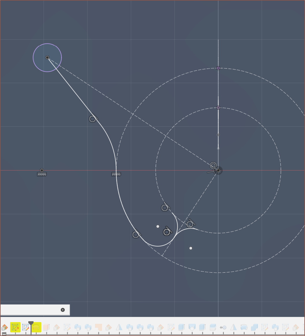
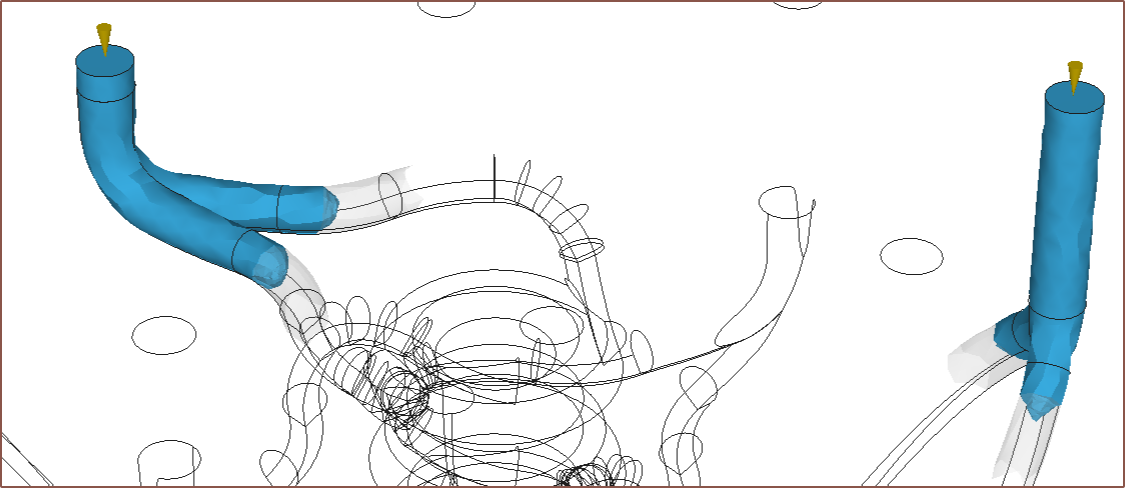
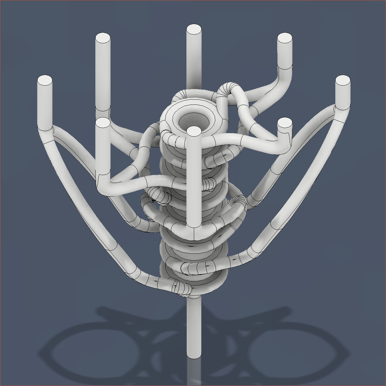
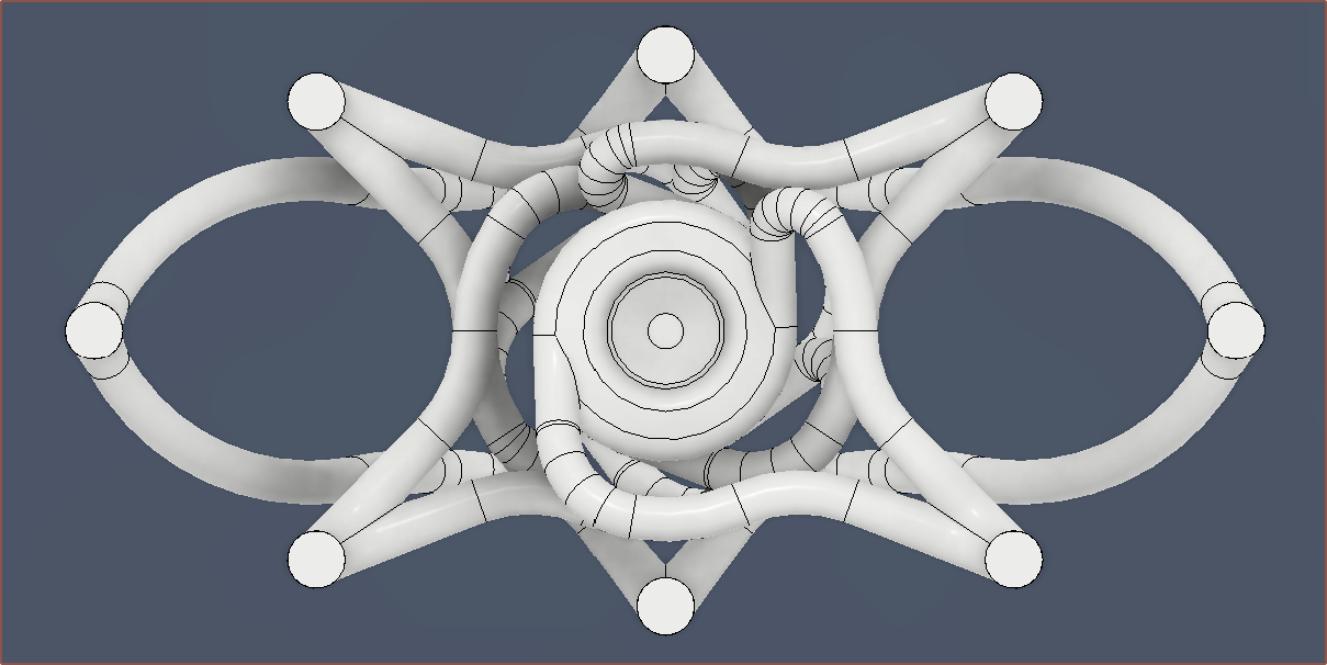
As the aim is to get consistent 360 degree pressure and the crosshead designs I saw yesterday weren't doing any centrifugal-like geometry, I've gone back to a simpler design with 2 inputs. I had considered 3 inputs but feared about pressure propogation delays and how channel 7/8 may have a different pressure profile than the other 6 since I can't just go straight through the heater cartridges. The sketch is shown below:
Well, that's half the reason. I was forced into it because the staggered approach caused minimum-wall-thickness violations.
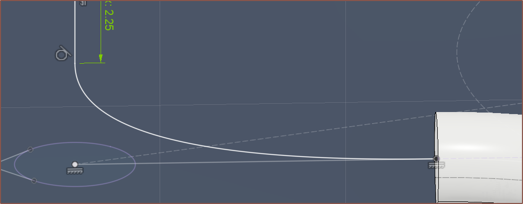
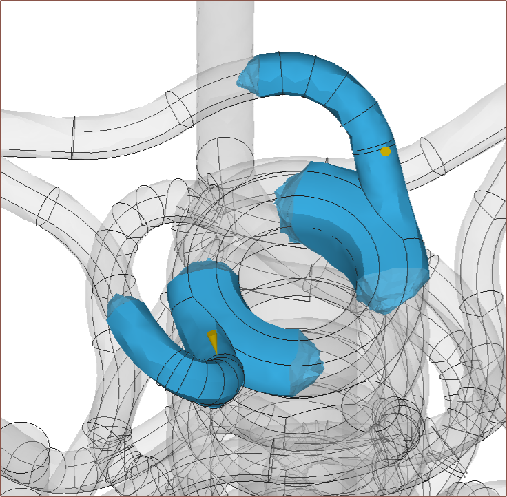
I then tried some conic curves to transition from the minor to major channel, mainly so that channel4 was more spaced from the paths of channel7.
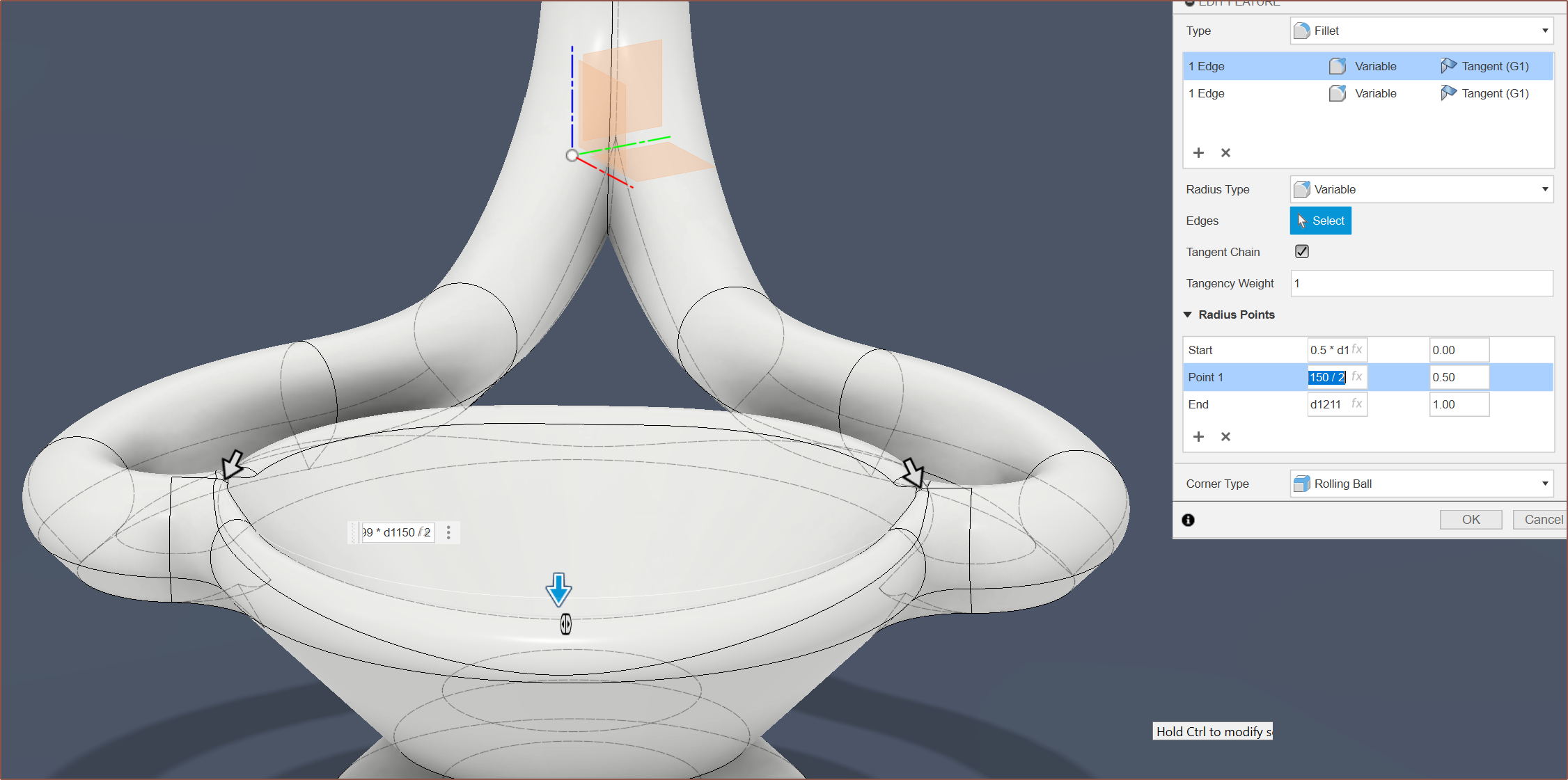
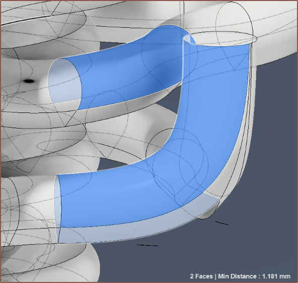
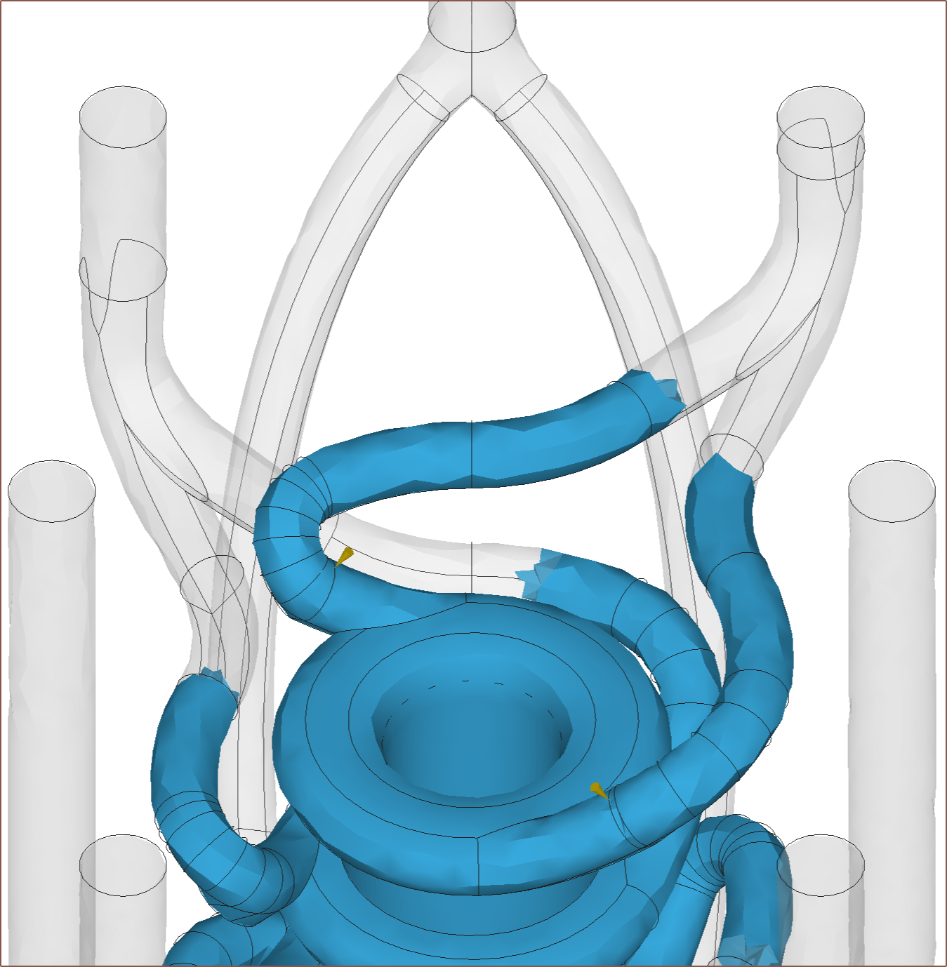
I did the revolve and then made this fancy variable fillet which aims to keep the pressure more constant as material moves further away from the inputs:
About 2 more hours of fixing later (which didn't help since Fusion decided to delete some features and sketches instead of just making them yellow or red) and I had the new geometry implemented. Almost everywhere was >=1.2mm minimum wall from what I could tell.
The heatbreaks go right to the edges of the bounding box, but I was still able to keep the 29 x 49 XY size.
First I tried something called draft analysis as I was hoping that I could use it to see overhangs over 45 degrees, but it seems limited in that it's only optimised for injection-moulding workflows and, as such, I can't set anything over 15 degrees.
So I did the usual...
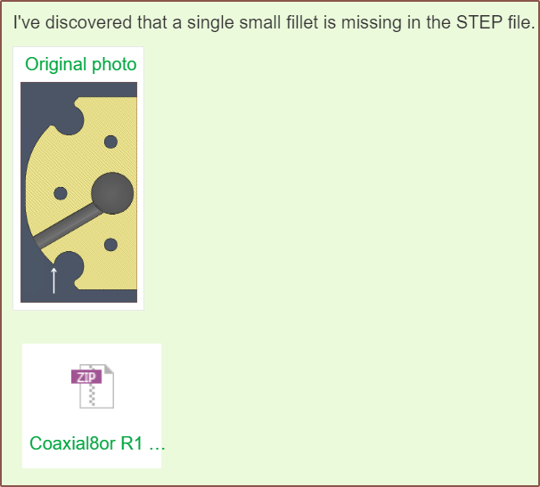
Read more »It started small. Small as in a small missing fillet. That was easy to correct.
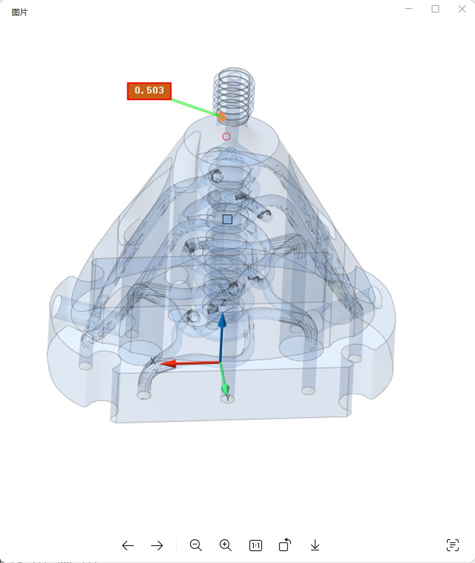
Then the engineer came back because they had concerns about the M6 threads:
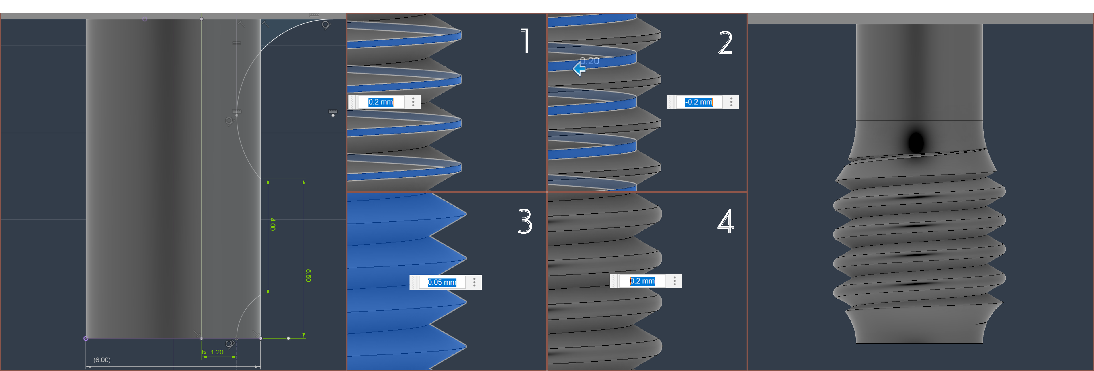
I looked at how Heinz did their threads and one thing I noticed was the taper before the flat wasn't a basic chamfer. I presume this is so that imperfections from the printed thread does not affect the important face that seals against the nozzle.
Thus I went in and did some modifications:
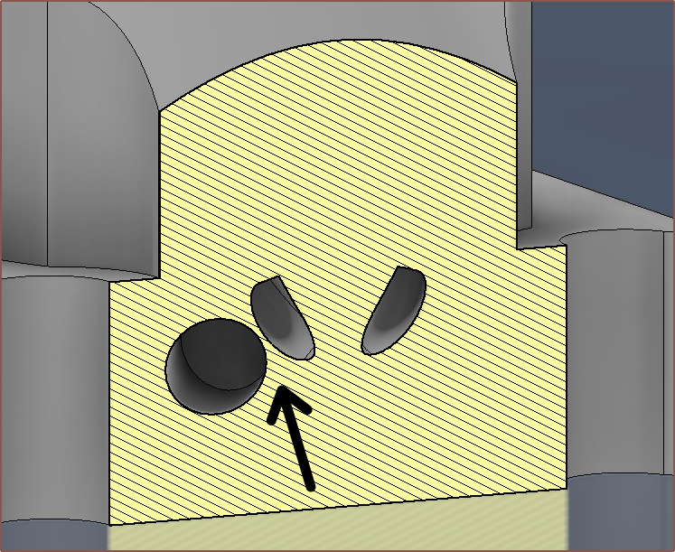
Then I was validating the model and found an extreme minimum wall violation that I unfortunately missed:
The hole is the grub-screw hole and so I had to rethink quite a bit of the design (and this is when I requested the order be cancelled since it could take a while).
Fast forwarding a bit, I moved the grub screws, reduced the clamp block thickness because it no longer had to fit the grub screws, and trimed the body of the heatblock so that I could simultaneously get under 20,000mm3 and $40 autoquote, and I got this:
So I was dancing about how my design is now 193cm3 and the autoquote was $38.80, and I was on Discord asking Heinz a few questions to get the latest insights in the technology tree. The response:
-- lots of colors are nice, but biggest improvement is in the coating meachanism itself imho.
-- making it as small as possible for less purge and quick color change
-- similiar to the cetus2 brass insert...
I was going to reply that I felt like colour gamut vs colour change speed would be one of those engineering challenges where one is forced to pick a side. I still feel that way, but that it's not as black and white as I originally thought.
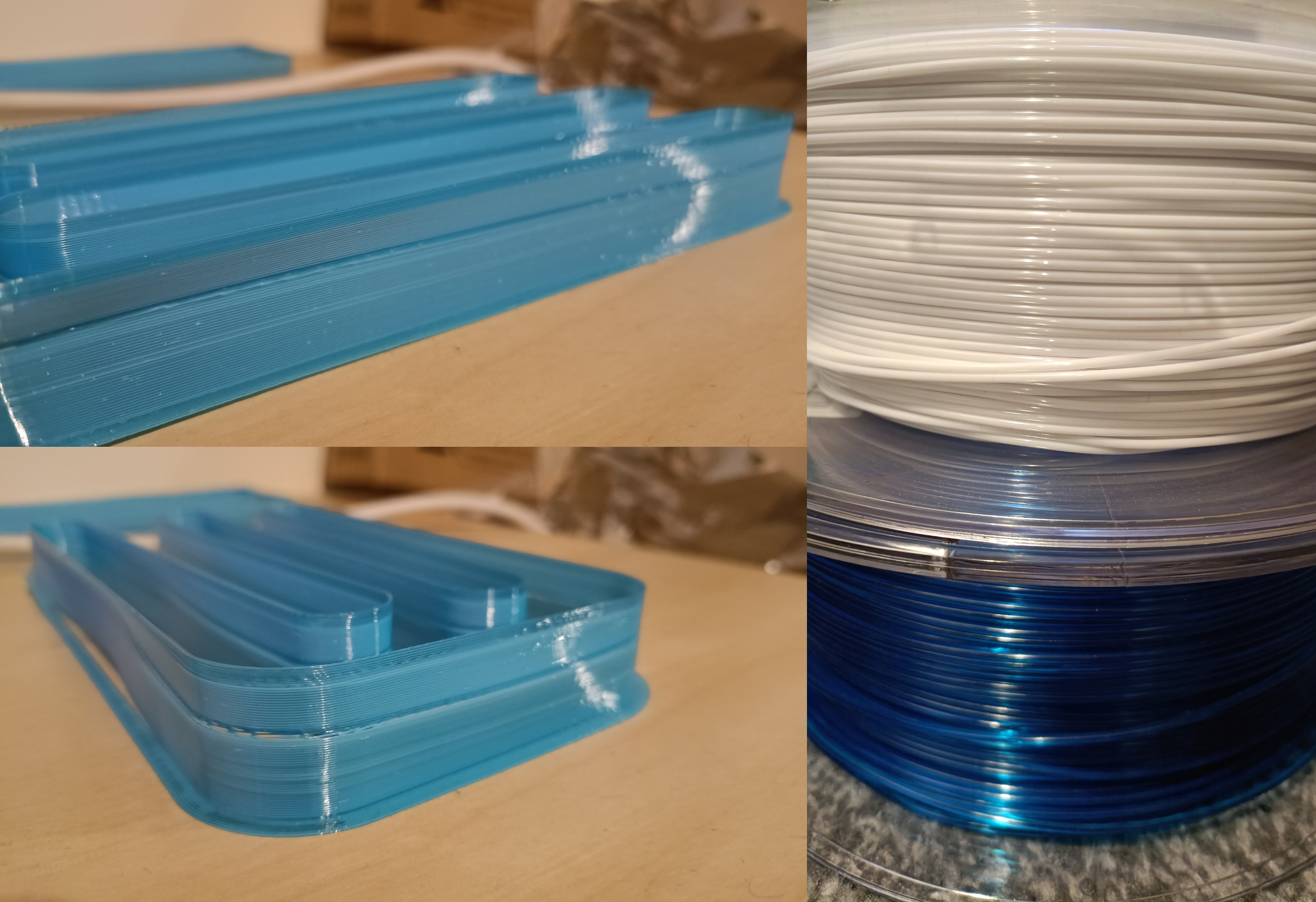
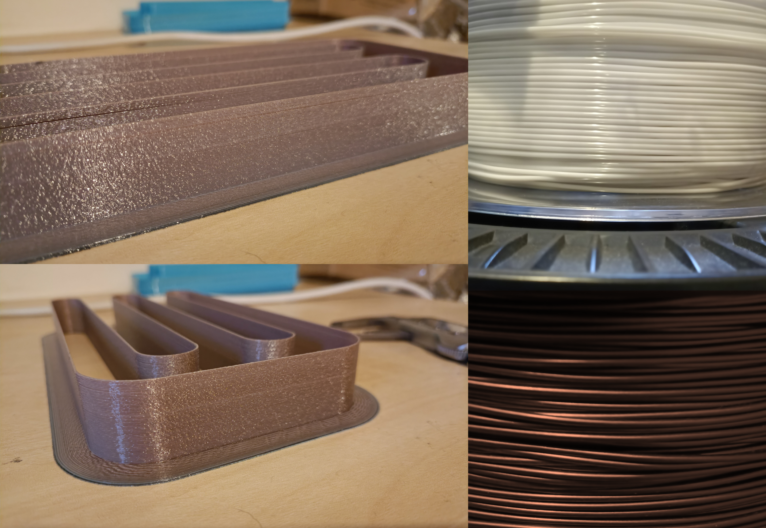
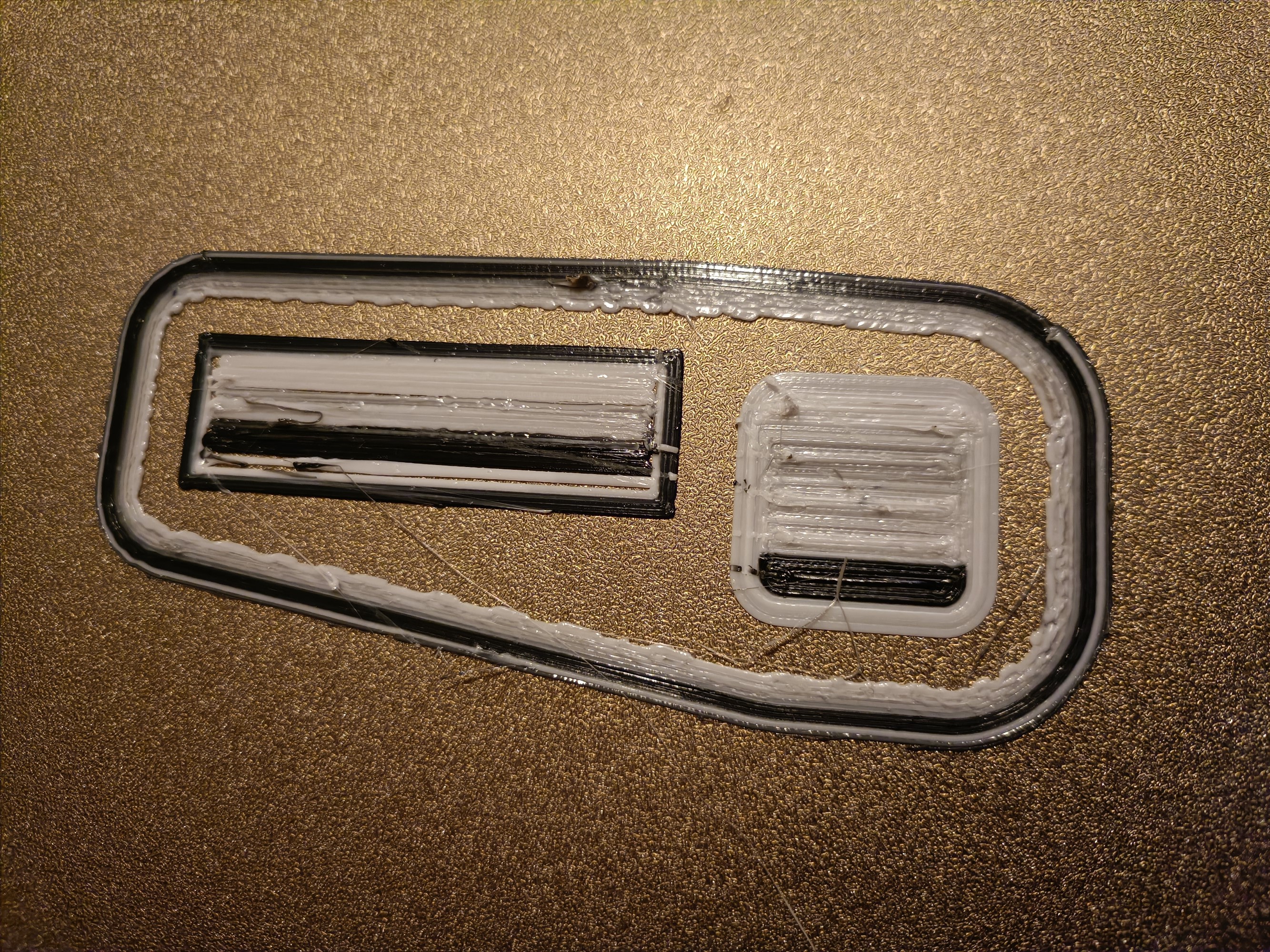
Remember that print of a clip that was supposed to be white but only got to a medium-light grey at best?
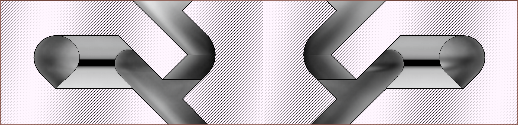
Well I looked into the model cross section and determined that I needed to reduce the contact zone between differing materials whilst still being manufacturable.
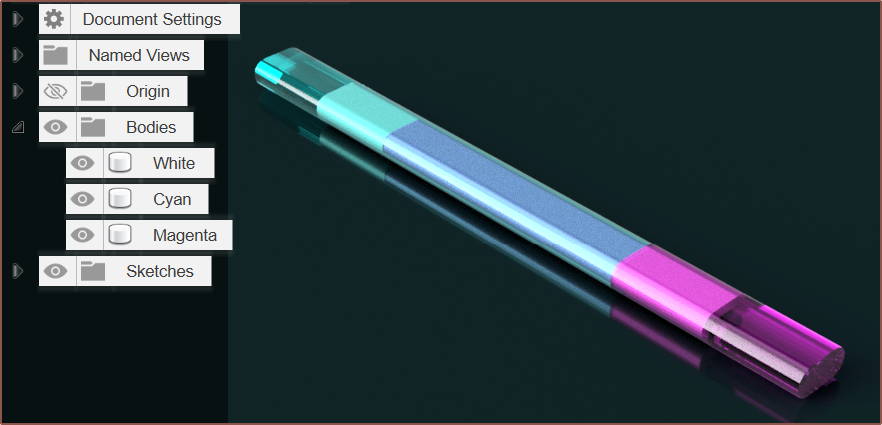
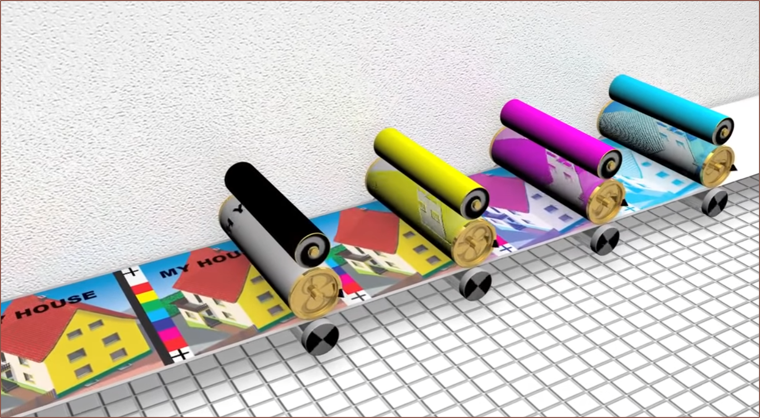
Ideally, colour changes inside the melt chamber would be like a Pallete filament splicer, but with molten filament. Another way to think of it is like a 1-dimensional version of offset printing where each colour is separated by some finite distance and the change in colour is a single point on the length of the pipeline:
I started sketching a solution that could potentially be geometrically viable yesterday:
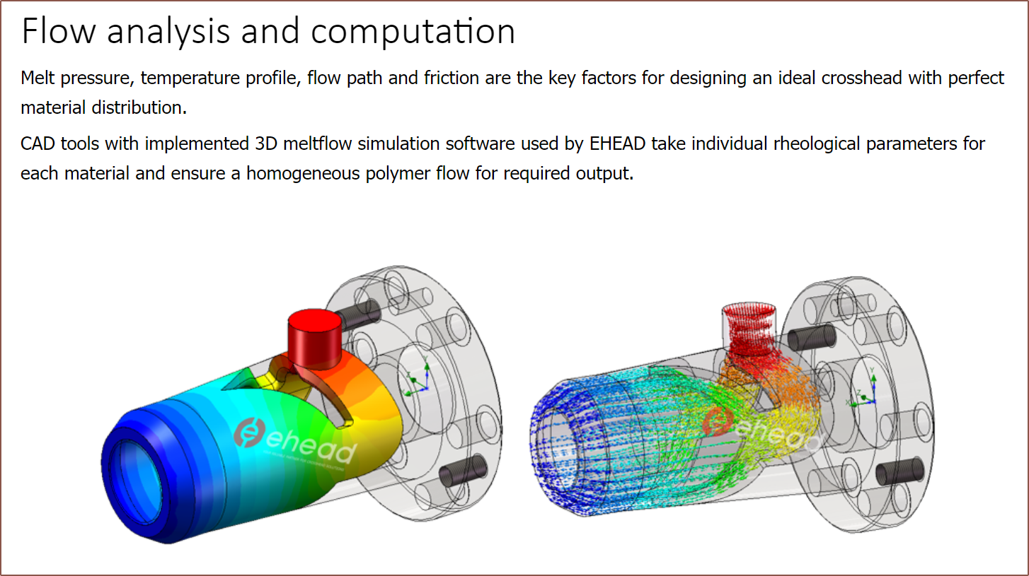
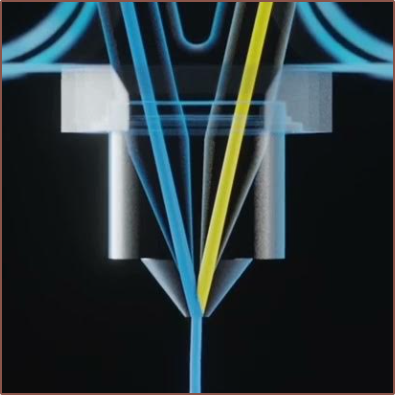
Today, I've looked into "Crosshead Extrusion", which is a method to coat wires with insulation:
I'm continuing to experiment with what I can do with the design whilst keeping it compact, ensuring a minimum wall thickness and keeping the pressure as axissymmetric as possible:
The idea is to make the geometry more like a revolved version of the Cetus2 nozzle for each channel. This is also to hopefully make push/pull vtools more effective.
Perhaps it's because this design is similar to R0 which PCBway already has experience on, but now the autoquote and the actual price were essentially identical. Unexpectedly, the "Standard Global Shipping" is now almost half the cost. Perhaps it has something to do with the bounding box of R1 being smaller than 50 x 30 x 50mm3?
Another possible reason for the lower price could be that the 1.5mm channels are easier to clean inside than the 1.25mm ones?
The current Mastercard conversion rate means that it will cost me £45.25.
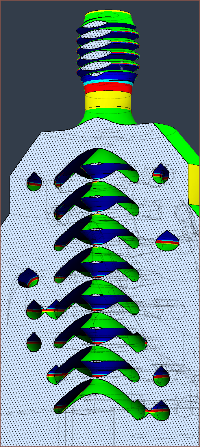
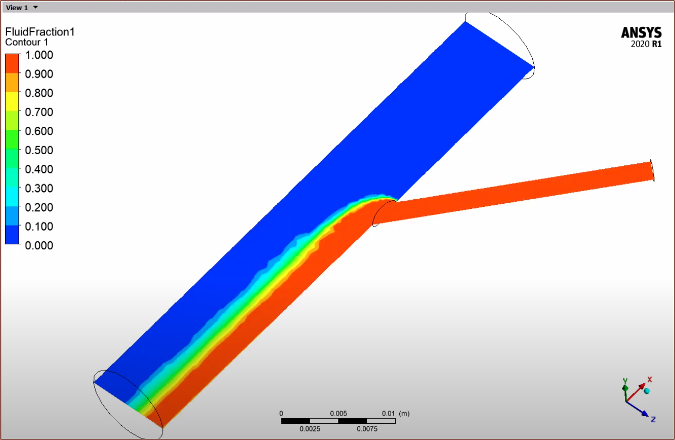
I was going to install the Windows Subsystem for Linux to try OpenFOAM, but then I found out and tried to use the injection moulding simulation feature in Fusion 360. Unfortunately, it complains if I set the mould temperature to something like 236C for PETG, and when I set it to within the recommended values, I got an incomplete fill animation:
[Apr 07] There was a material called "Bionolle" that had a close melt and mould temperature of 115C and 80C respectively, and I moved the inputs so that I could at least see the filling of the coaxialiser and path length matching.
[End of Apr 06 edit]
I signed up for SimScale but it became apparent very quickly that I'd only be able to simulate liquids like water and oil.
Ideally, it seems that I'd need something like Ansys Polyflow, which seems to be able to simulate coextrusion:
I did the mental calculations and thought that it would take at least 5 hours to clean up the Coaxial8or R0, since solid plastic is difficult to remove, and then it would take another 2 or so hours to put everything back together again, as well as 1 hour for resolving anything that I didn't account for.
That's 8 hours. I've seen Stuff Made Here scan jigsaw puzzles, and suspect it won't be the first and only time I'd find myself in this situation now that I need to find a new gasket material.
I have instead spent 4 hours updating the design of Coaxial8or R1 to hopefully increase flow rate and prevent any future leaks from melting onto the surface of the heating elements.
I think I now understand what I've heard in the past about "safe failure modes", in that in the event that the system fails, at least it fails nicely. Putting the cartridges on the underside means that I could have the heatblock heated when cleaning off plastic. The only concern with this solution is that it's possible for one of the heater cartridges to fall out onto the print if not sufficiently secured.
As you may be able to see, I've now replaced the T-like intersection between the major and minor channels for more of a Y-like intersection:
Since the thermistor is no longer in the centre, I've also reduced the diameter of the internal column to 4mm. I still feel like it's important to give the molten material something solid to build upon, especially when the main coaxial-ising section is 30mm long. I tried to reduce it but I wasn't able to. At least with this diameter reduction, the cross sectional area drops from about 20mm3 to 14mm3, which should notably reduce the amount of internal material.
Bounding box is now 49 x 29 x 49mm XYZ and the heatblock is 23,200 mm3.
I also tried to make the M6 thread more printable but Fusion generated so many faces and froze when I tried to offset them.
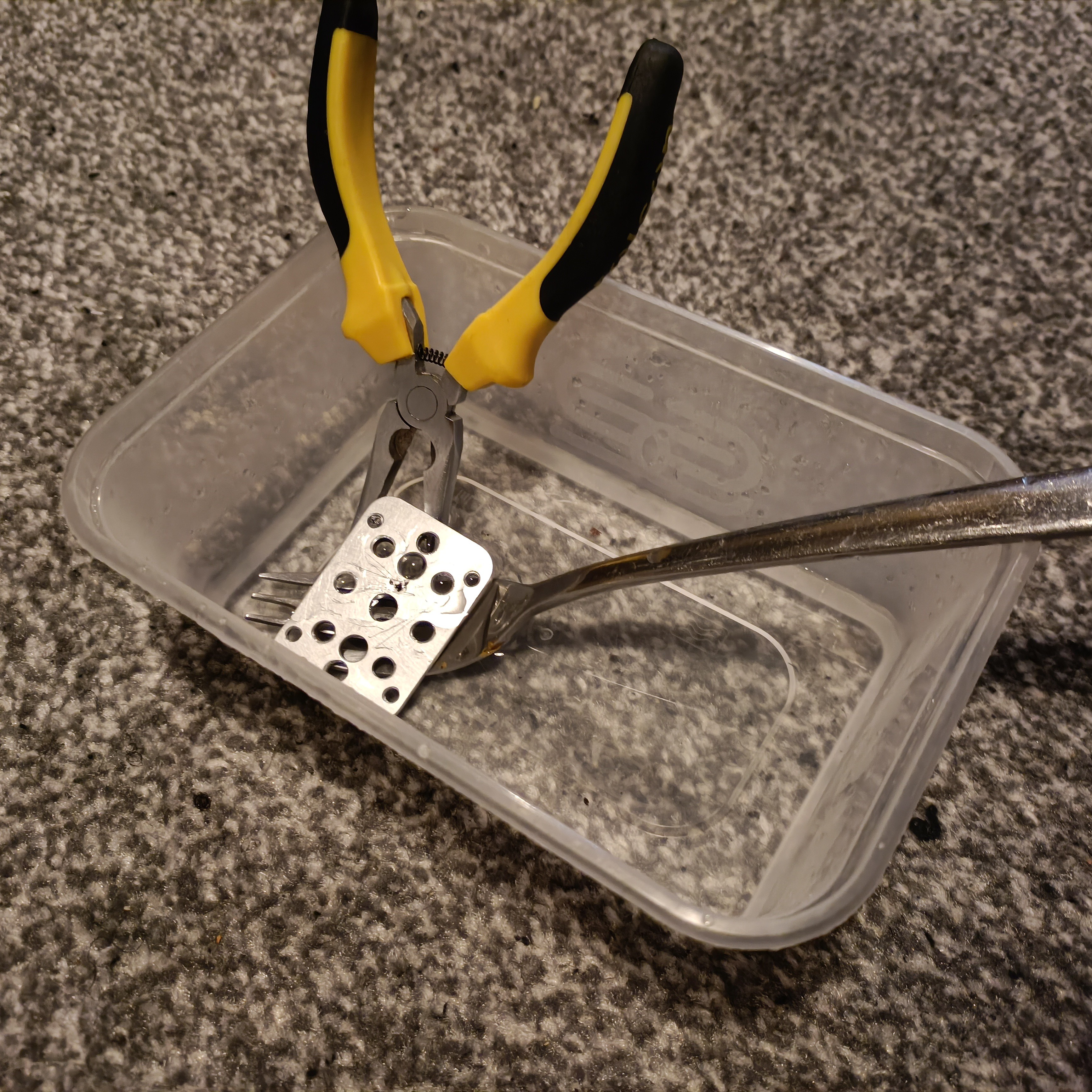 Yes, I retrieved and cleaned up the clamp plate from Coaxial8or r0. I pried off the plastic and cartridges from the clamp plate, then put it in the above tub along with a shallow amount of kettle water so that the PETG softened and I could clean off the rest.
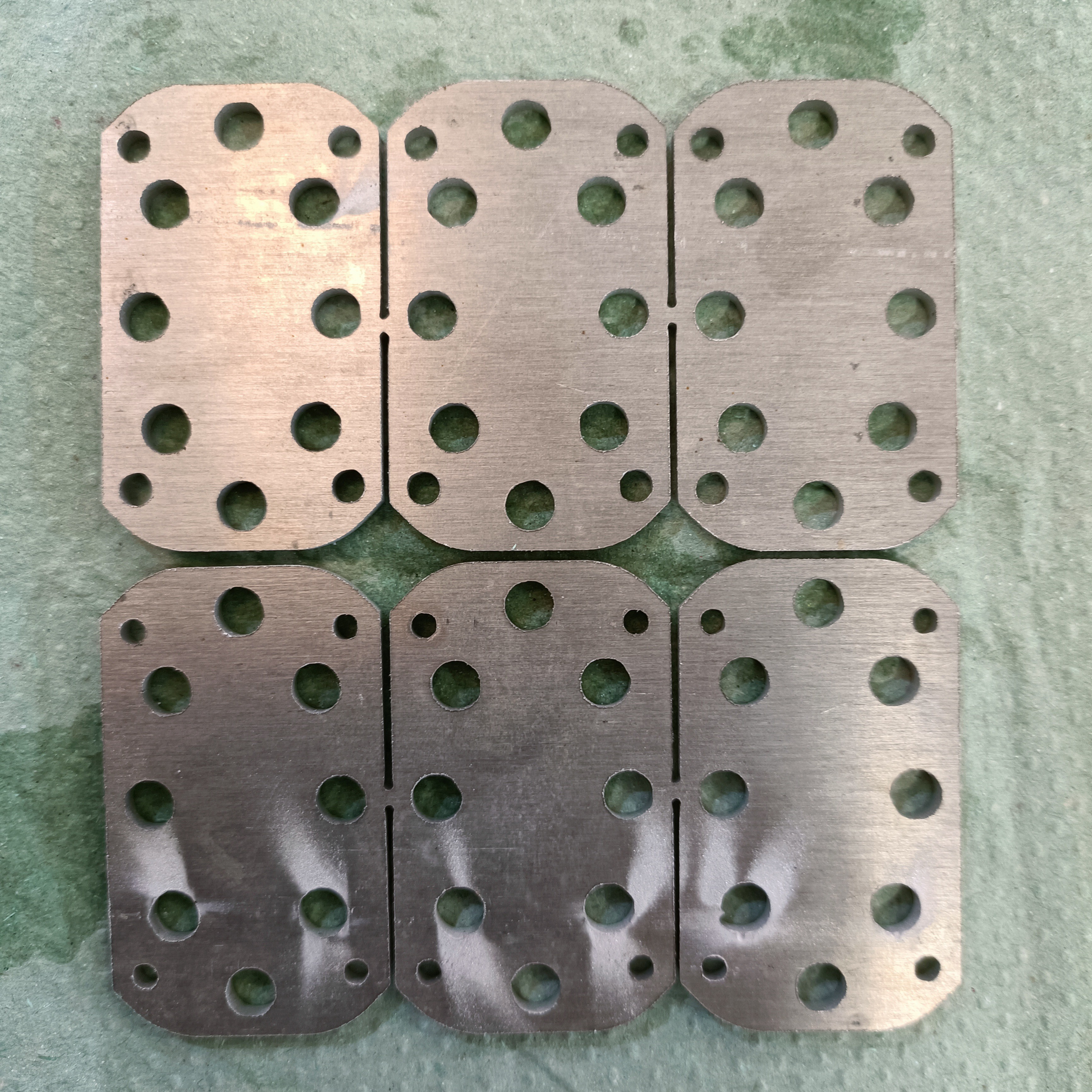
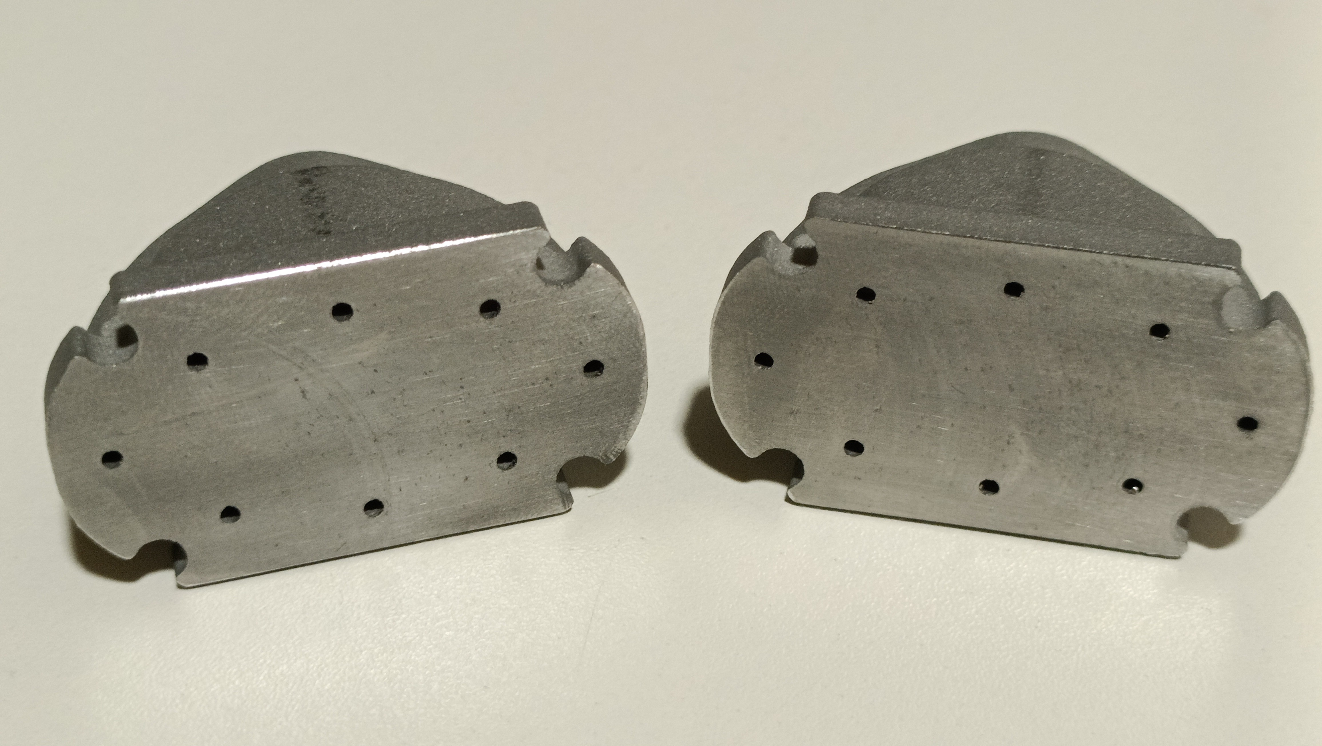

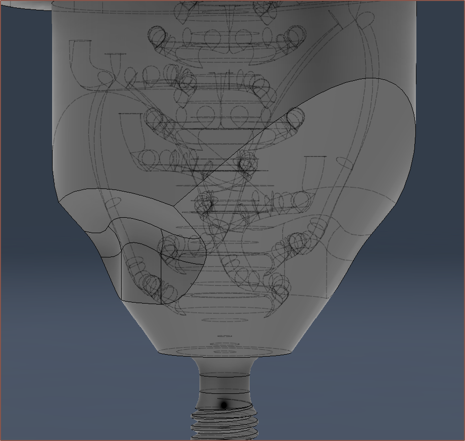 I first tried doing the trim with an extrude and draft angle but it just looked... wrong... so I instead created a cone surface and extruded to that, which actually trimmed off even more material.
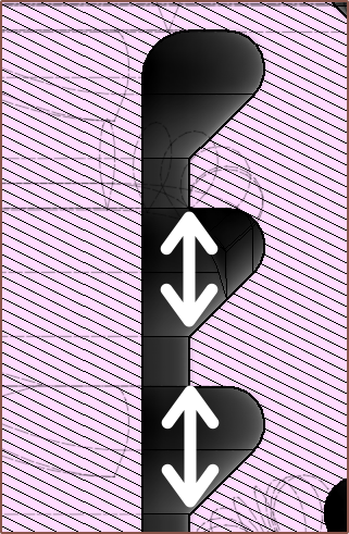


 Daren Schwenke
OMG!!!! we need to talk! josh@jrt3d.com