 E/S Pronk
WIPKAT BOOTSTRAP
Core Concepts
I want to build a printer without making use of a kit, custom 3d printed or machined parts. This rule is mostly about the structural part of the printer, not the printhead / nozzle / extruder etc. It should be made from generic parts so that we have some room to improvise and customize.
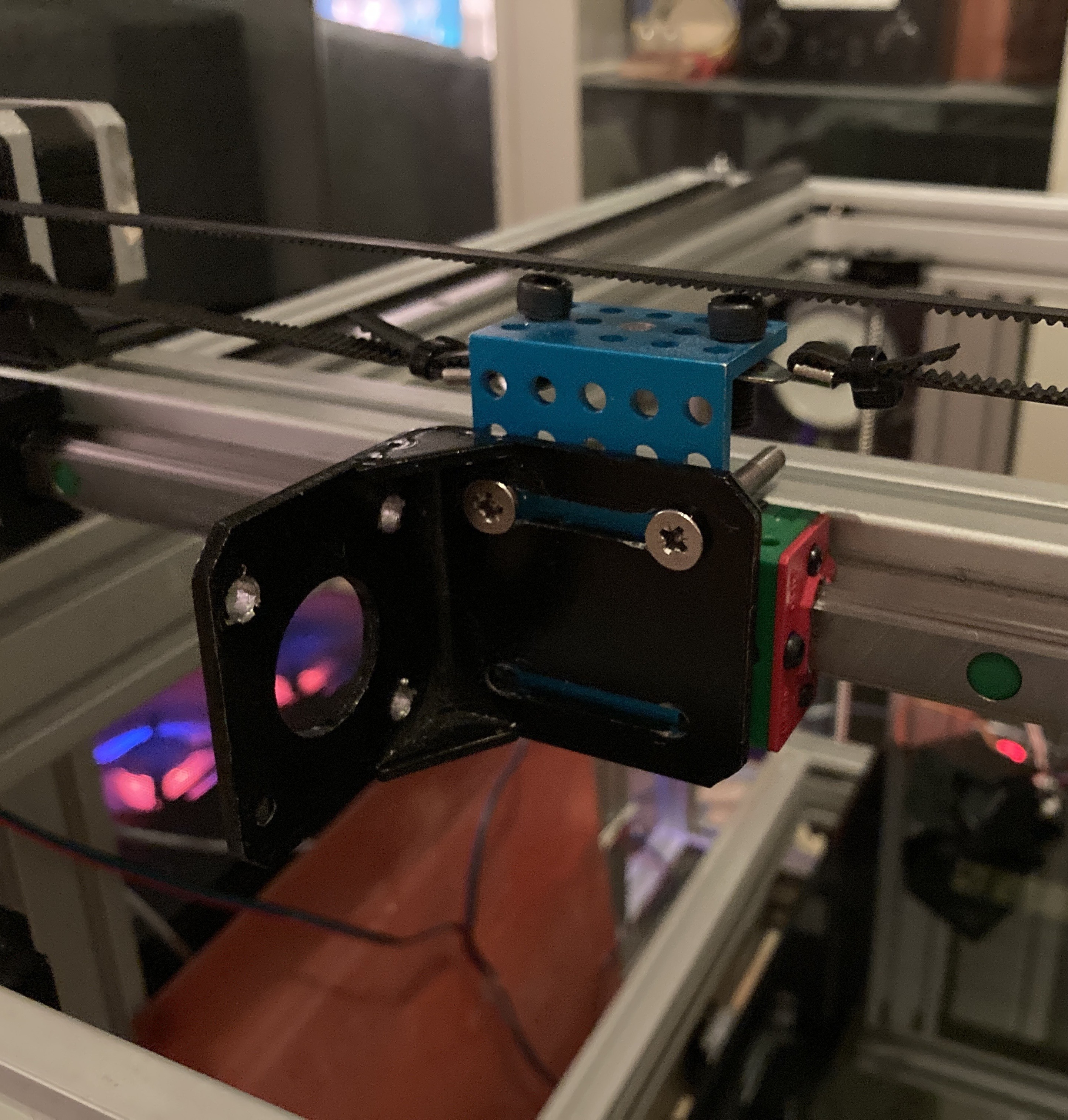
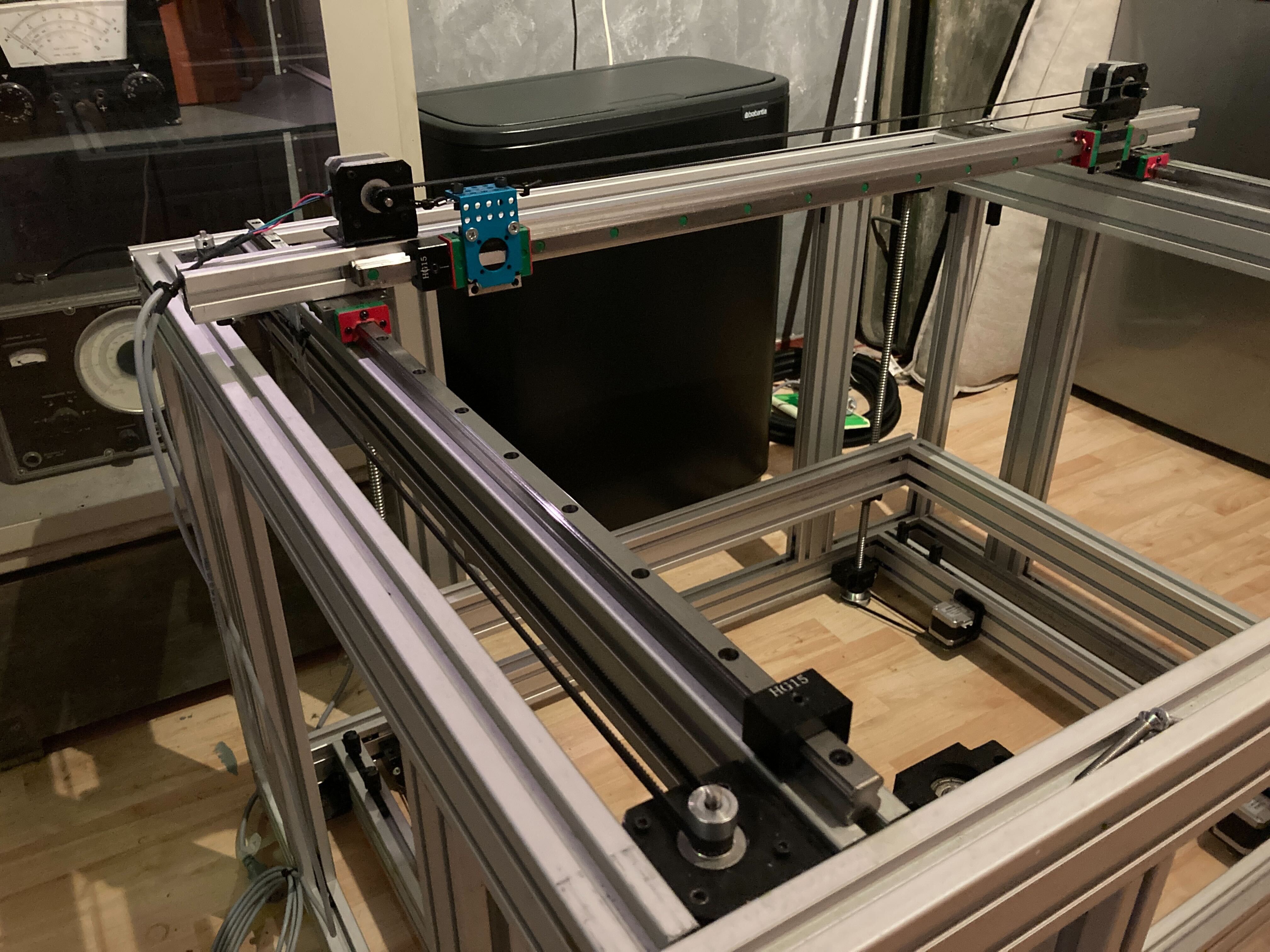
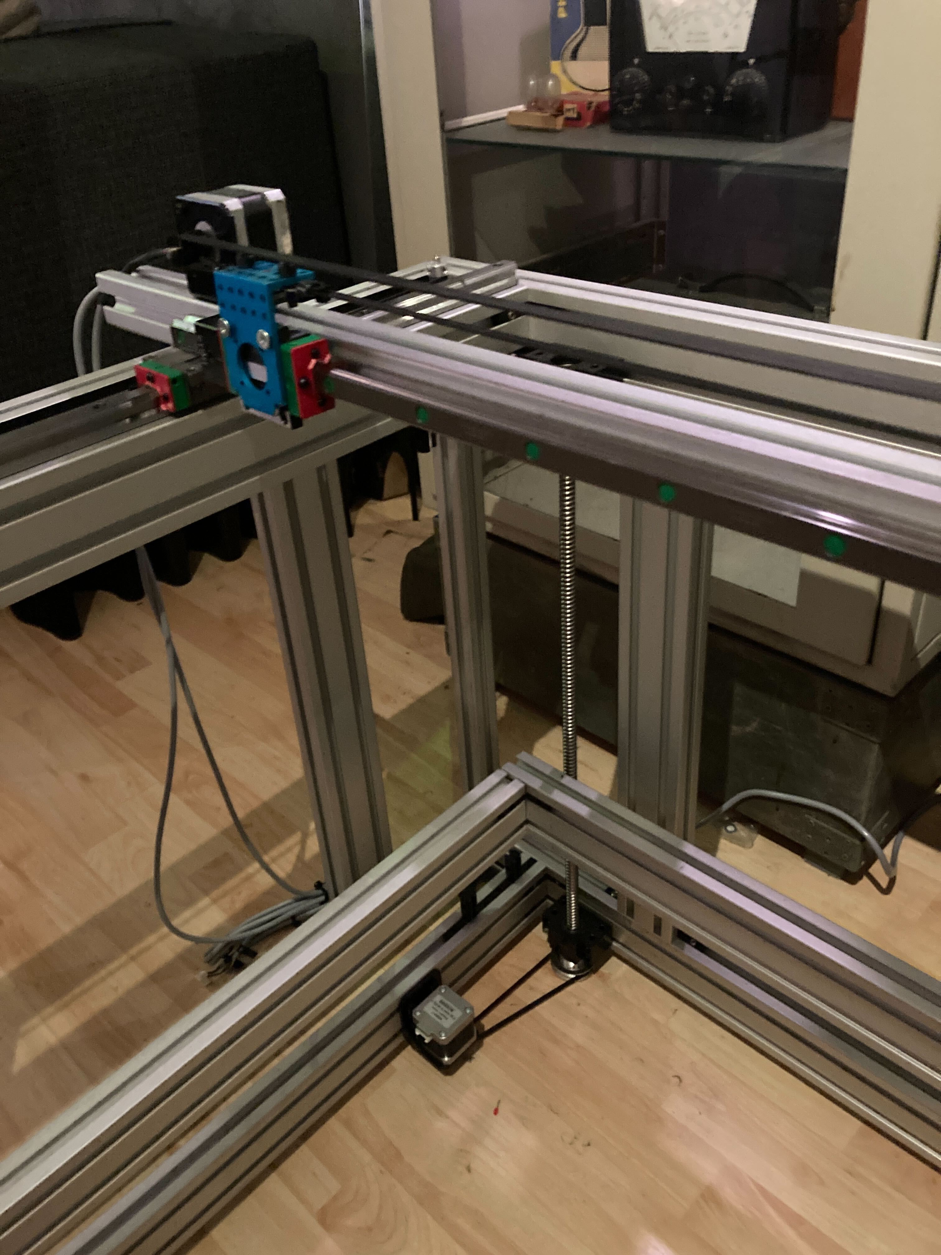
Dual Motor Setup
One of the main features of the printer is that it uses a second motor where you'd normally use a pulley. This is because:
- I have a lot of motors laying around
- A motor isn't that much more expensive than a pulley + bearing + mount + axel
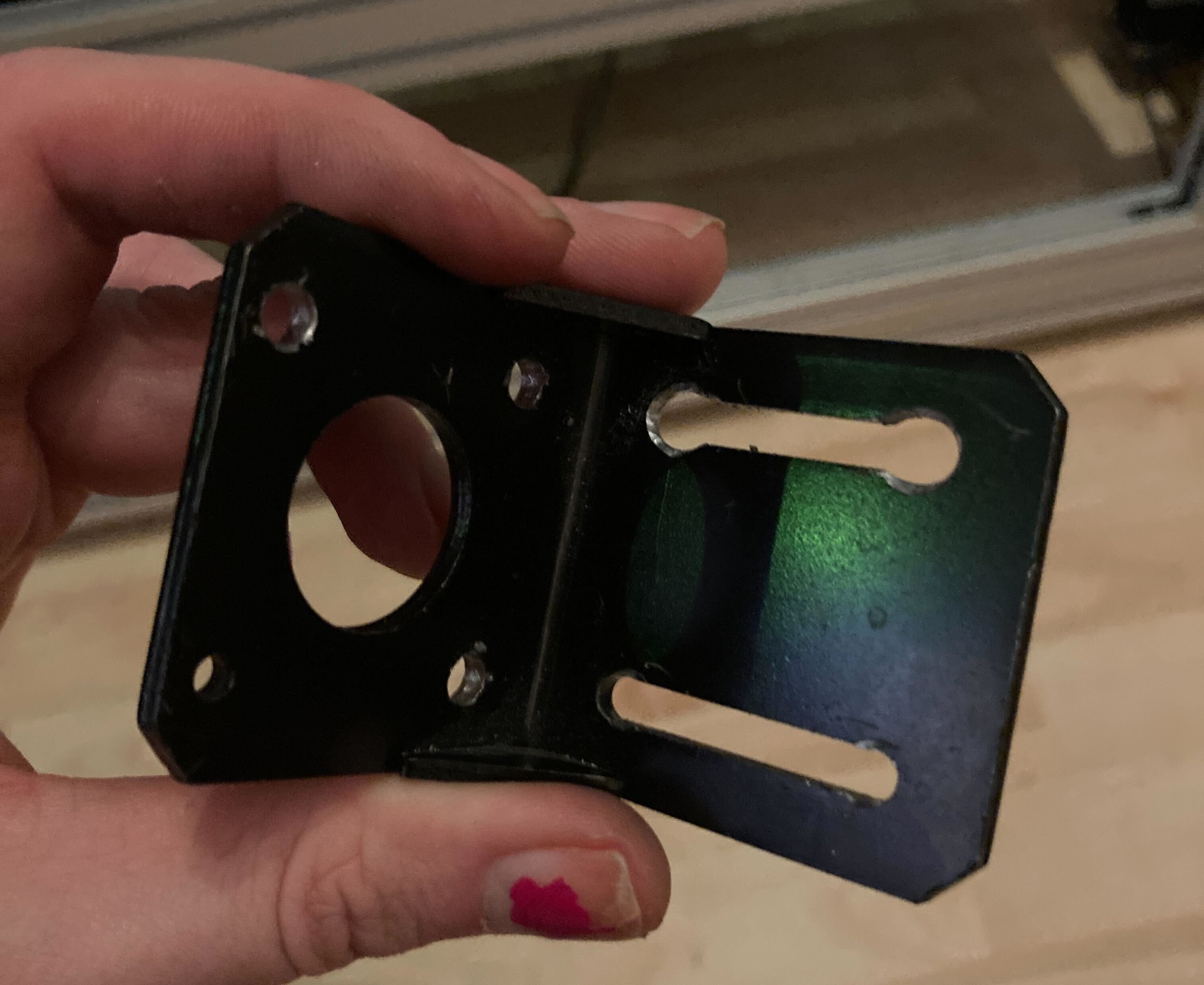
- It is harder to align a pulley, especially when only using generic parts, than mirroring the motor.
- You divide the load between the 2 motors, they can run cooler or be combined for more torque.
- Counter rotating the motors before a print is a neat way to tension your belts.
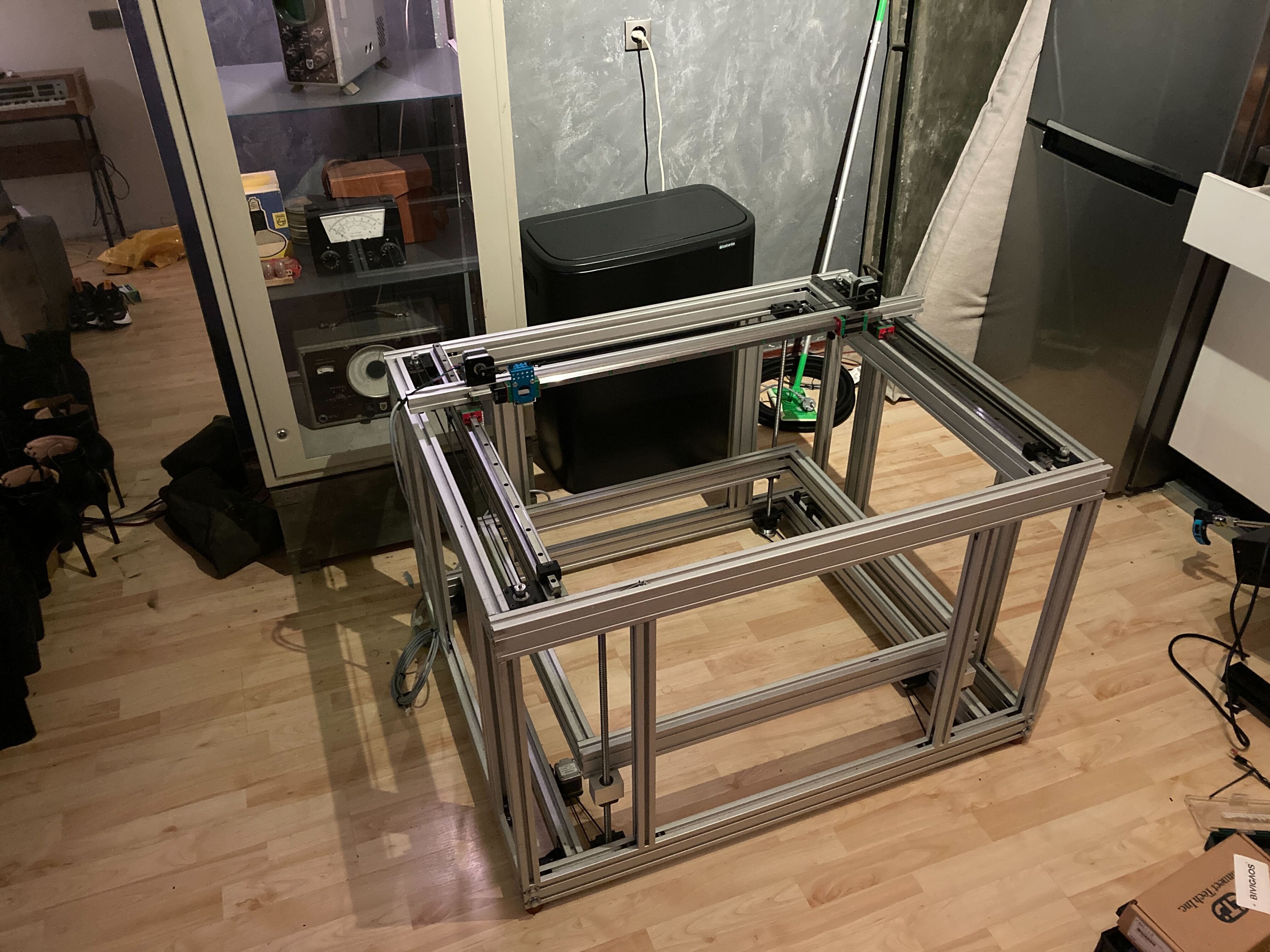
Scale
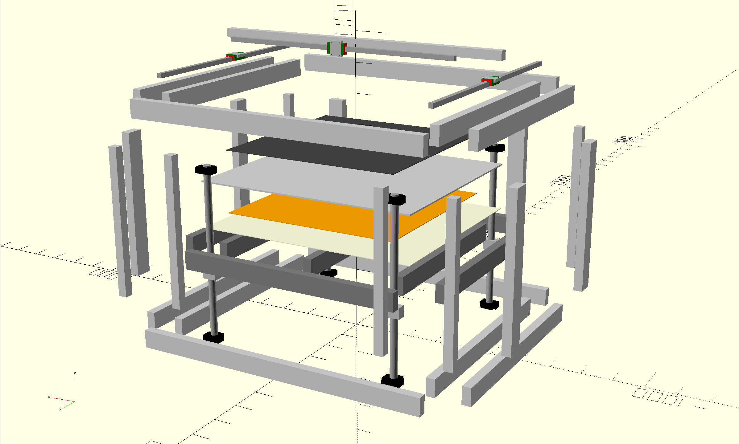
I think many large scale printers are scaled up versions of small printers. They will use the same rails, gantry designs and kinematics. However, sizing up changes the relative weights of the components. Where a motor used to be too heavy to be on a moving part of the printer, and complicated kinematics like CoreXY came to the rescue, on larger printers a small NEMA17 might not add that much weight relative to the gantry weight. This allows us to simplify the design of the printer, by having the X motors ride along with the X axis.
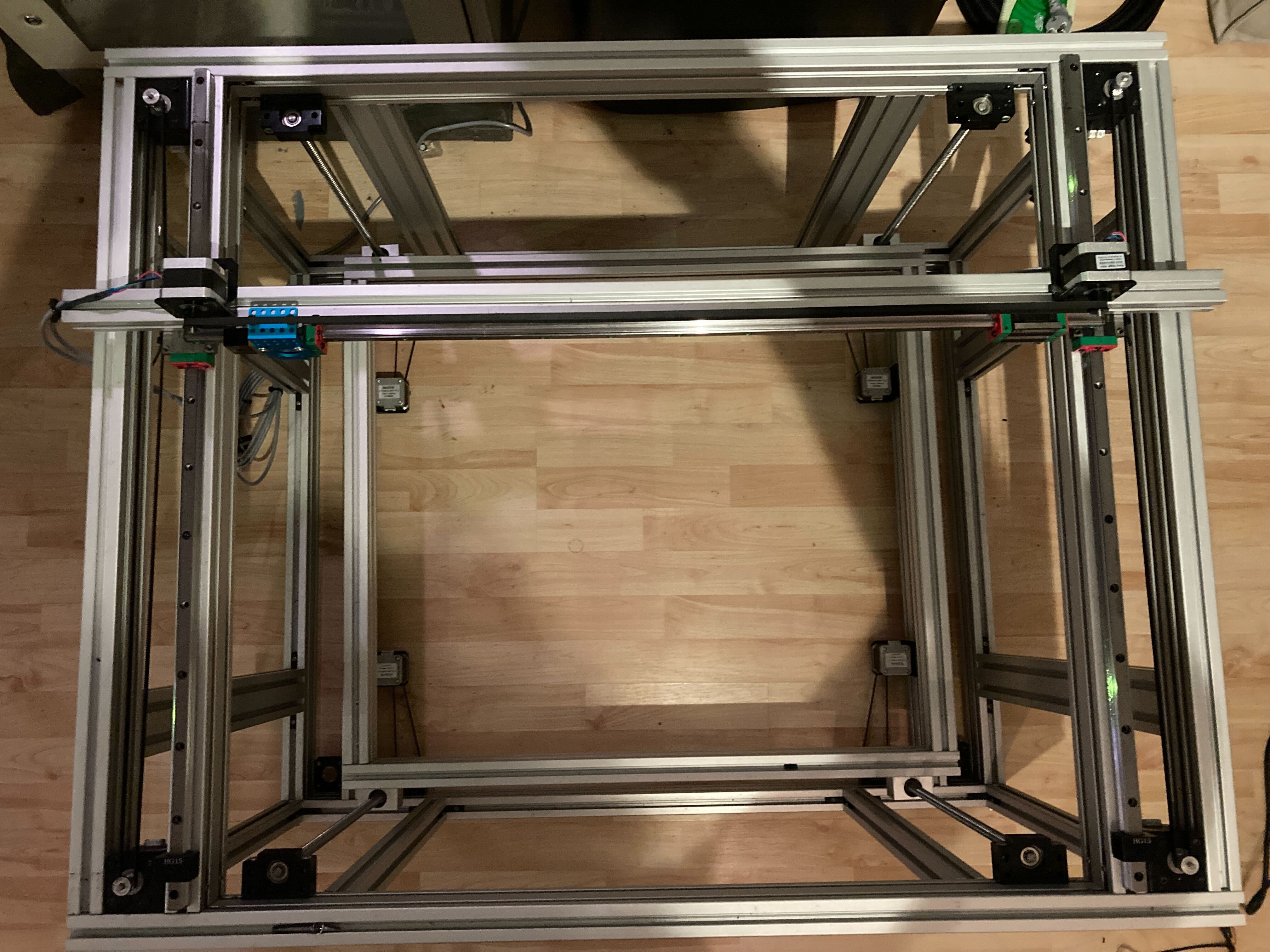
I'm also investigating whether MGN rails are really worth it on this scale, because they are very expensive when you need longer rails. The HGR15 rails seem more suited to the scale of the printer I have in mind, but obviously this is a gamble as there are not that many examples out there in the community using these rails, nor are there any parts available that interface with the larger carriages.
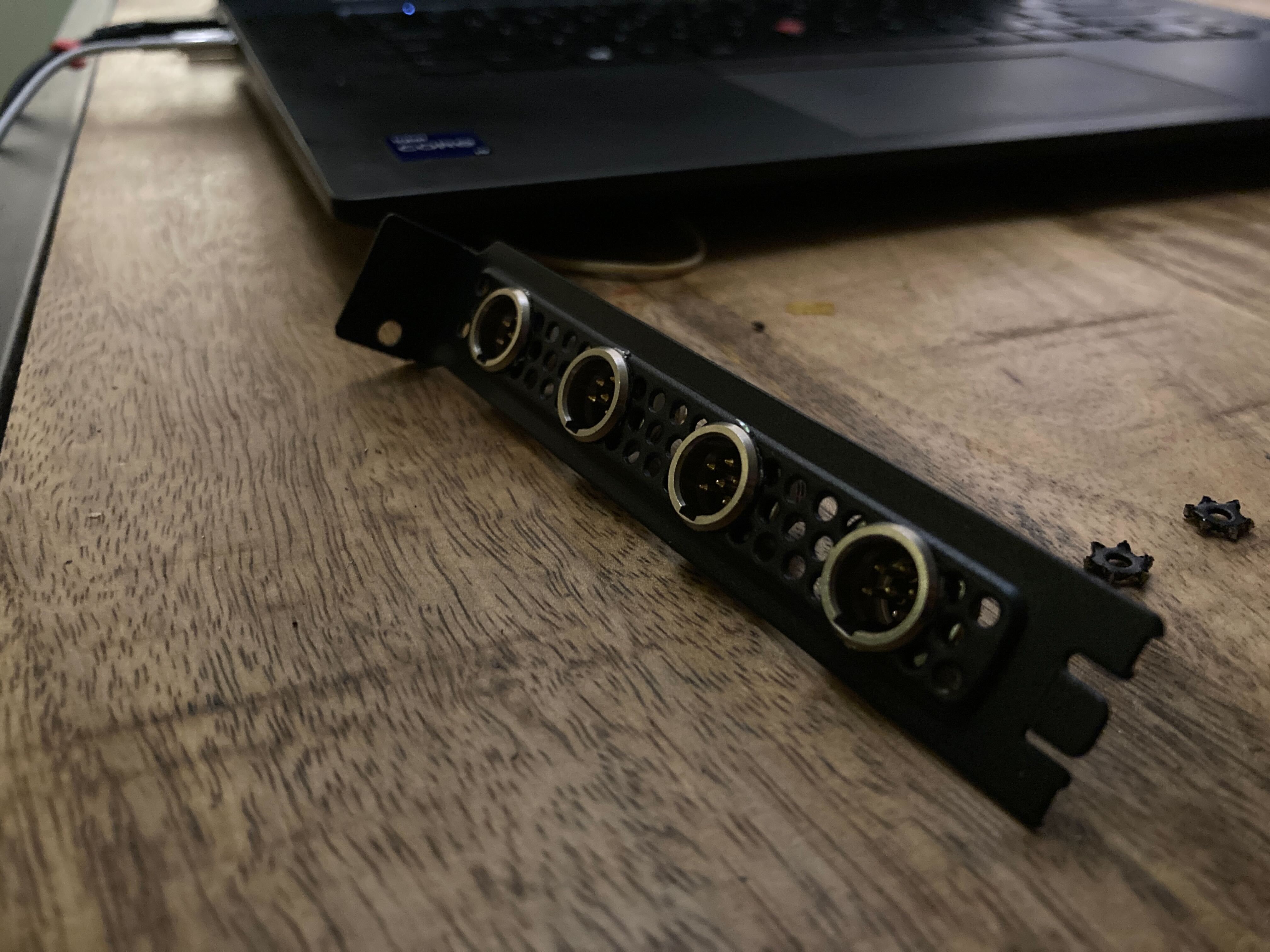
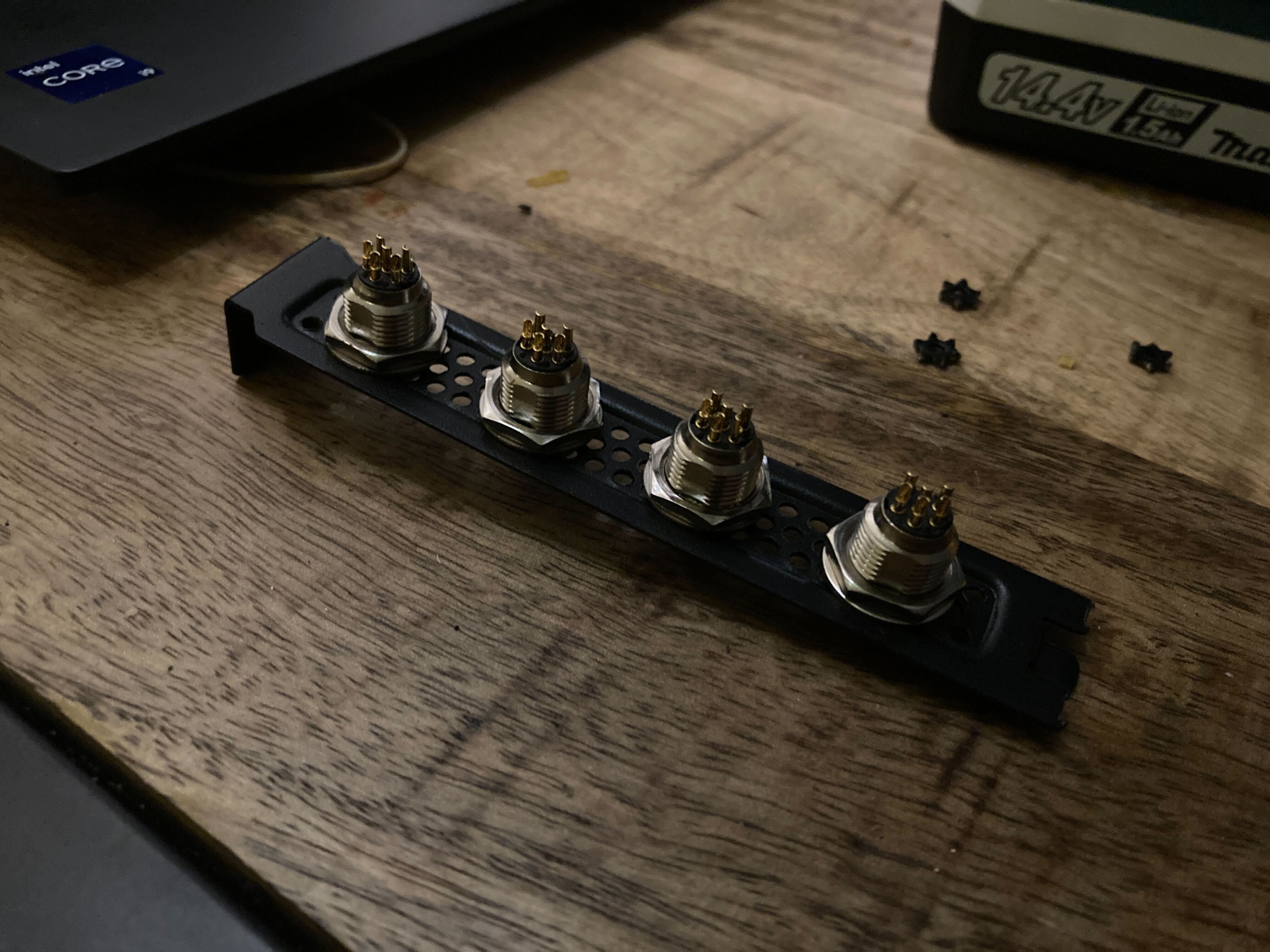
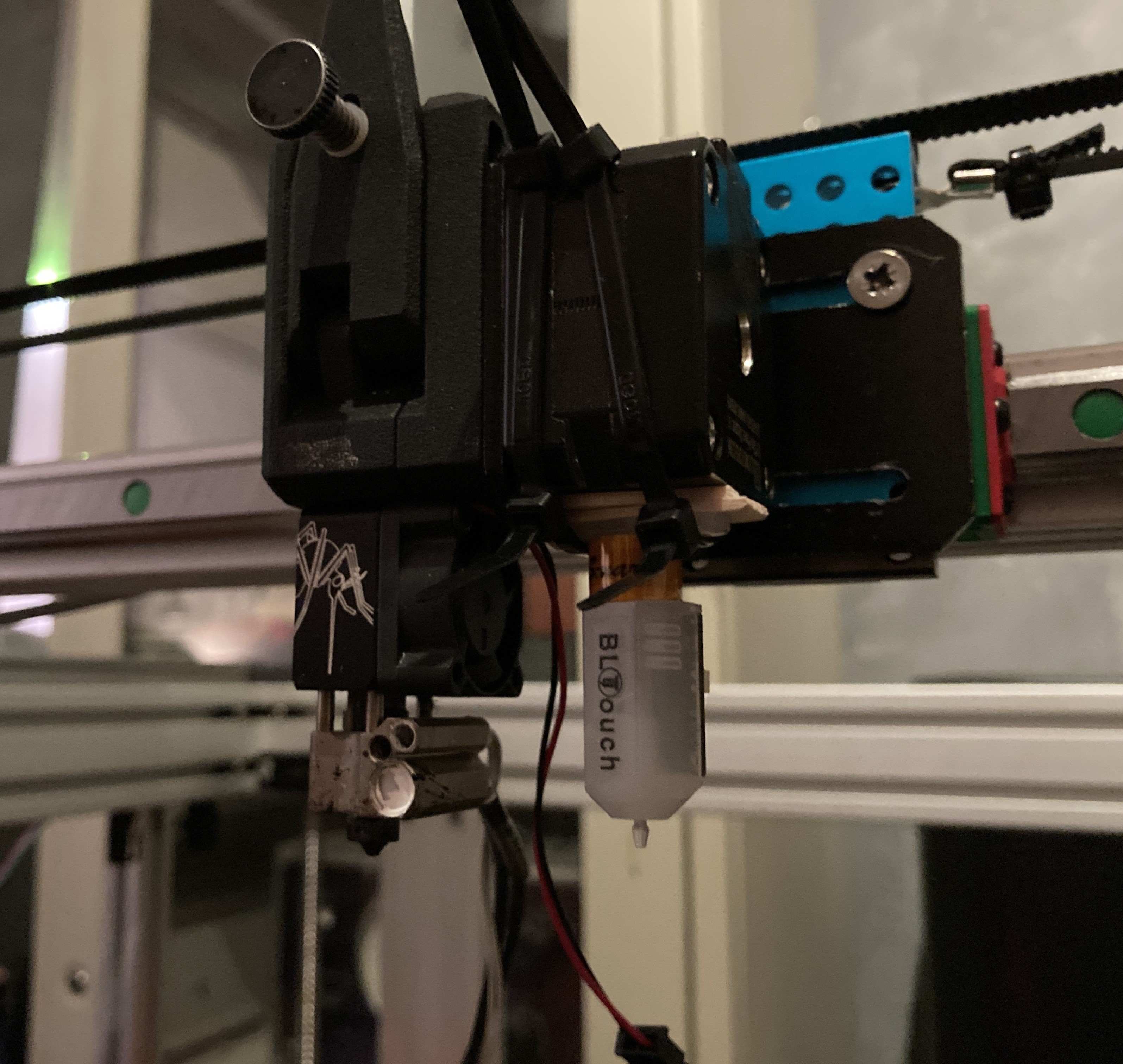
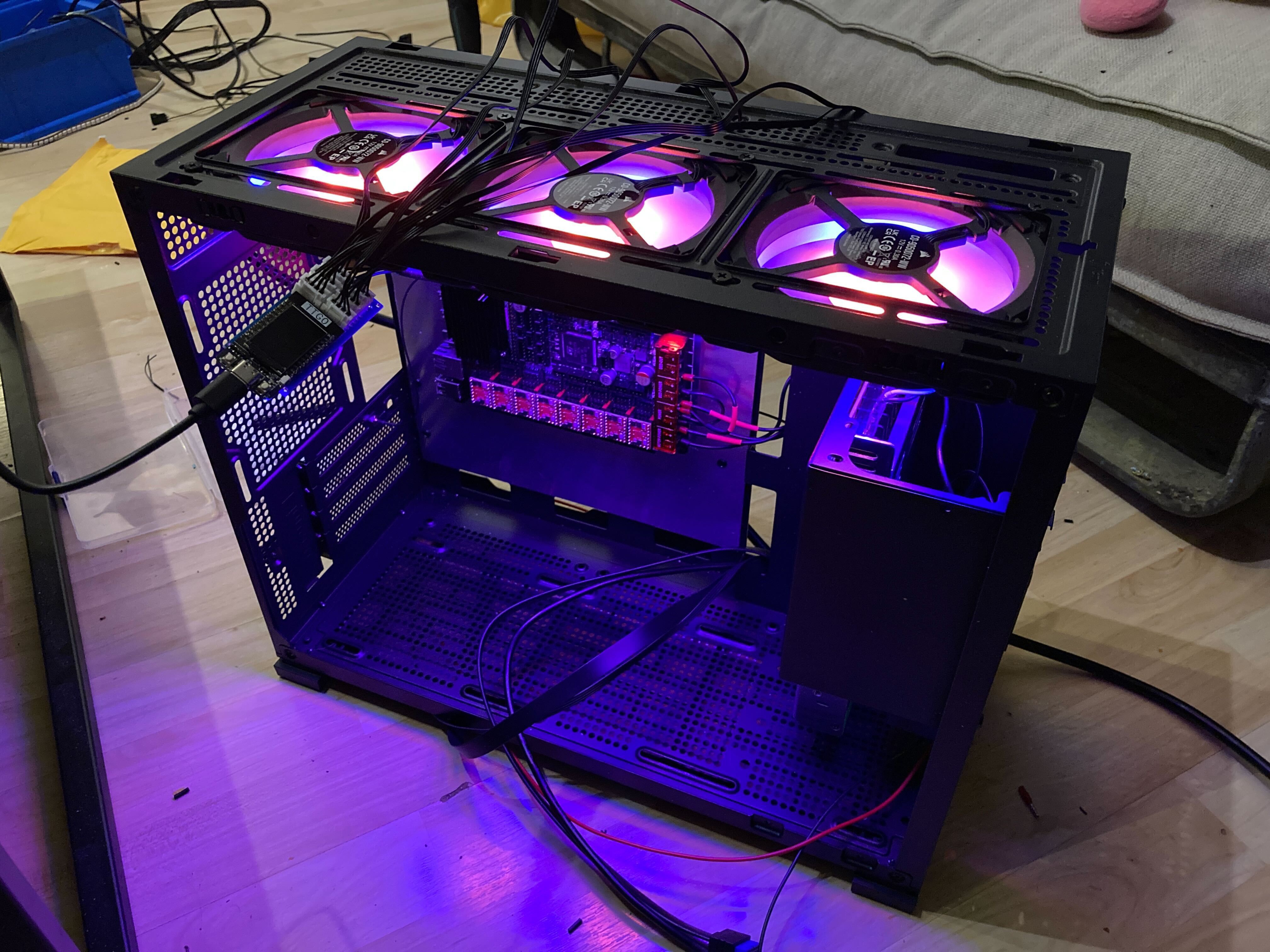
To offset for the increased weight I am using a lot of motors in dual / quad motor setups (4x Z, 4x Y, 2x X, 1x E) combined with TMC5160 motor controllers, which should give me enough power to connect pairs of motors to a single controller in parallel (because the main board doesn't have 11 slots for motors, only 8). To combat stresses on the frame and vibrations I'm going with 3030 frames, which also limits my options when shopping for parts that fit nicely to the rail (everything is 2020)
The Goal
The initial goal for this printer is to be good enough to print its own upgrades, while providing enough quality for my day to day (hobby) 3d printing needs. Then keep making it better and better, I have a lot of ideas, like multiple extruders, a heated chamber, and other toolheads like lasers or maybe even paintbrushes? We'll see!


 Chris
Chris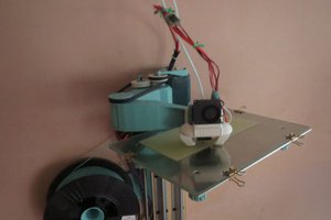
 dekutree64
 Sci
Sci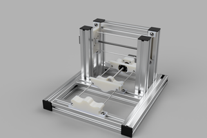
 Myles Eftos
Solid project, love it!
(you're probably adjusting belt tension via the motor mounts. I'll leave a link to my write-up on belt tensioning with a re-purposed hose clamp here for your enjoyment and inspiration: https://hackaday.io/page/7198-hose-clamp-style-gt2-belt-tensioners)