 Rue Mohr
Pages? lets try this...
Hi I'm Rue, you may know me from such places as the internet, the information superhighway, and the world wide web.
You may be familiar with the practice of 'circuit bending' often used by hardware hackers to create musical instruments that in turn are used to create compositions questionably referred to as music. ( ;] )
I am indeed a type of minimalist, as such I prefer not to bend circuits, but to bend chips.
I have come to you today to talk about bending the LM555 chip. I know you know this chip, everyone knows this chip, its more famous (slightly) than the 6502, its less powerful than the Z80, and it has more gates than a PN2222. This set of bending will be done within the constraints of using the 555 as an RC oscillator, I wont get into using it as a digitally annunciating/resetable window comparitor that drives a relay, or a crystal oscillator, or a logic gate, or a monostable or its uses for vogon face detection, just an oscillator.

(Now I just dive in)
So, here is the standard 555 circuit you might be familiar with, its... the ( quite boring ) standard circuit...
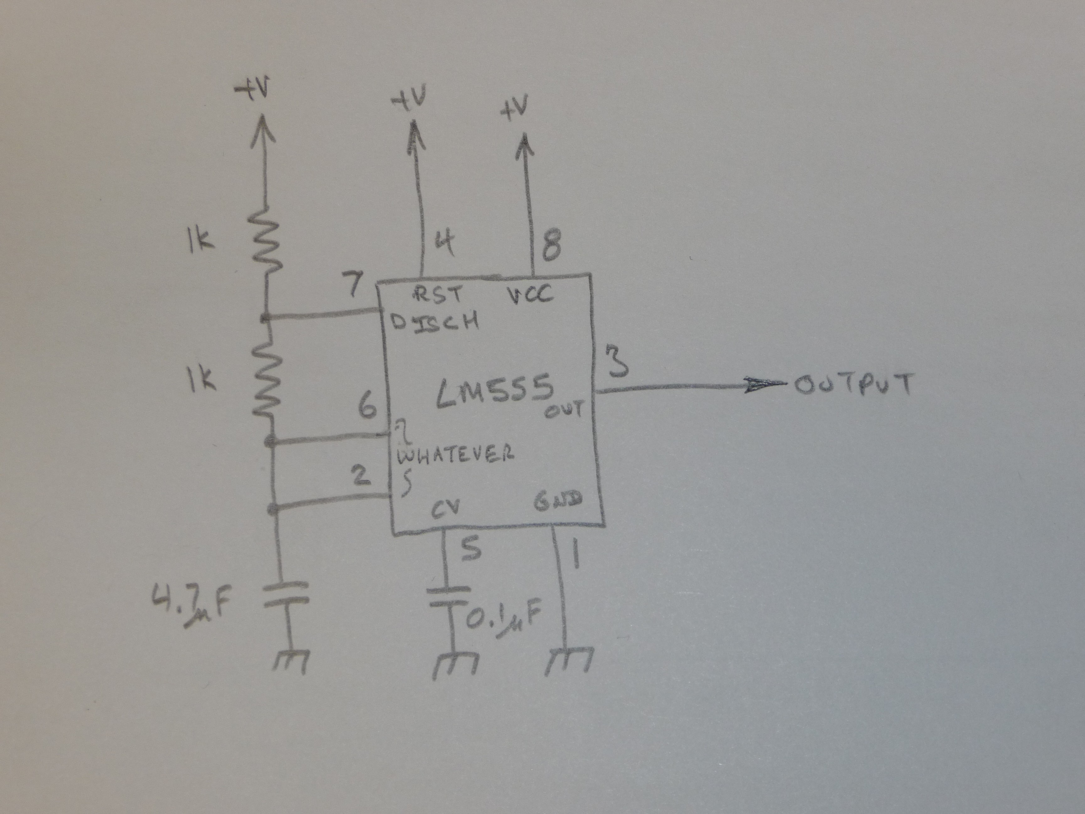
So, there are a lot of parts here we don't need.
Lets start with that wire to pin 4. If your using a 555 that is NOT CMOS, it will pull up pin 4 past the reset voltage just fine on its own. so, you don't need that.
And we have almost the same circuit.
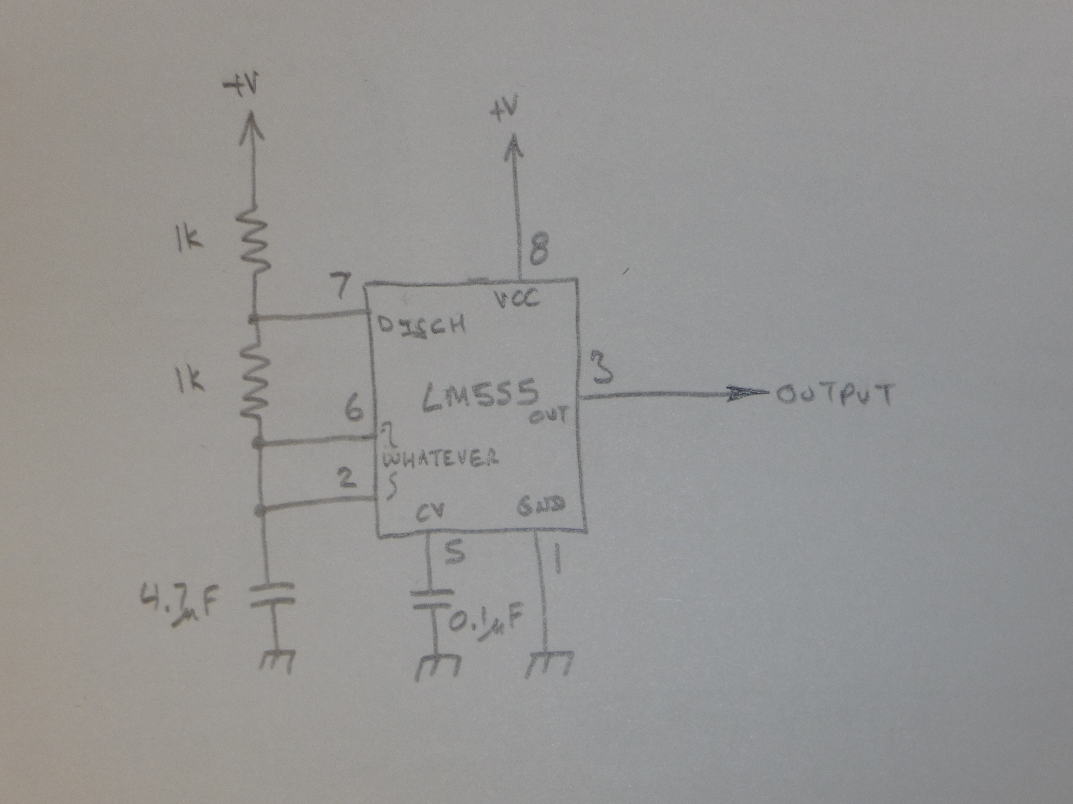
Now, if your using a clean power supply (of course you are) you don't need the capacitor on pin 5.
Nice, we removed a real component. 🎉
This circuit works by a sort of funny its-not-a-voltage-divider. The capacitor is charged thru the two resistors, and when the chip goes into discharge mode, it switches pin 7 to ground, and discharges the cap thru R2. (whilst grounding out VCC thru R1 )
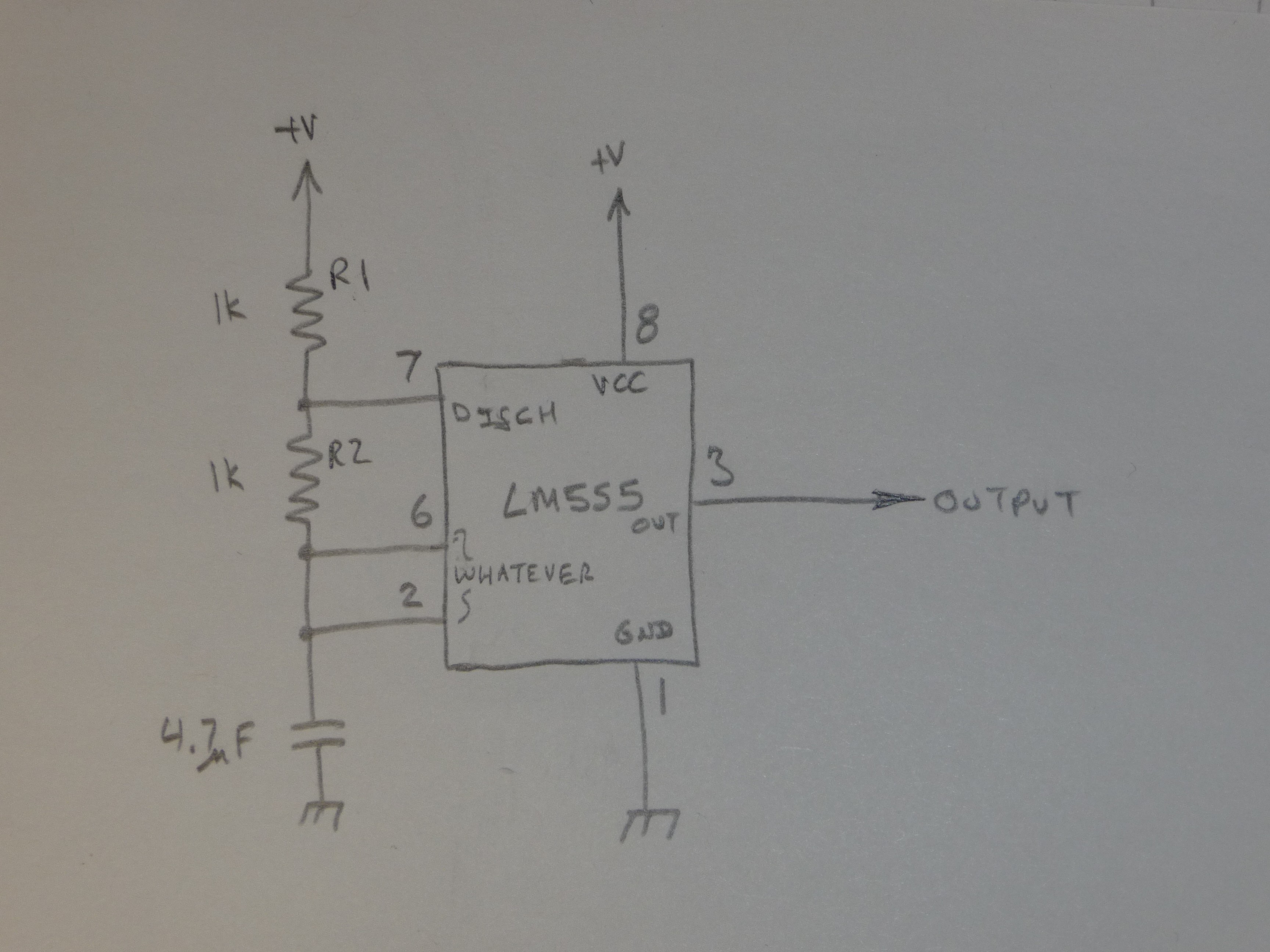
But... we don't need to do that.... Pin 3 goes to ground at the same time pin 7 does, but pin 3 goes to positive power the rest of the time. This can be used to charge AND discharge the capacitor.
So we can ditch a resistor and put the other one between the 2,6 node and 3
so we end up with this..
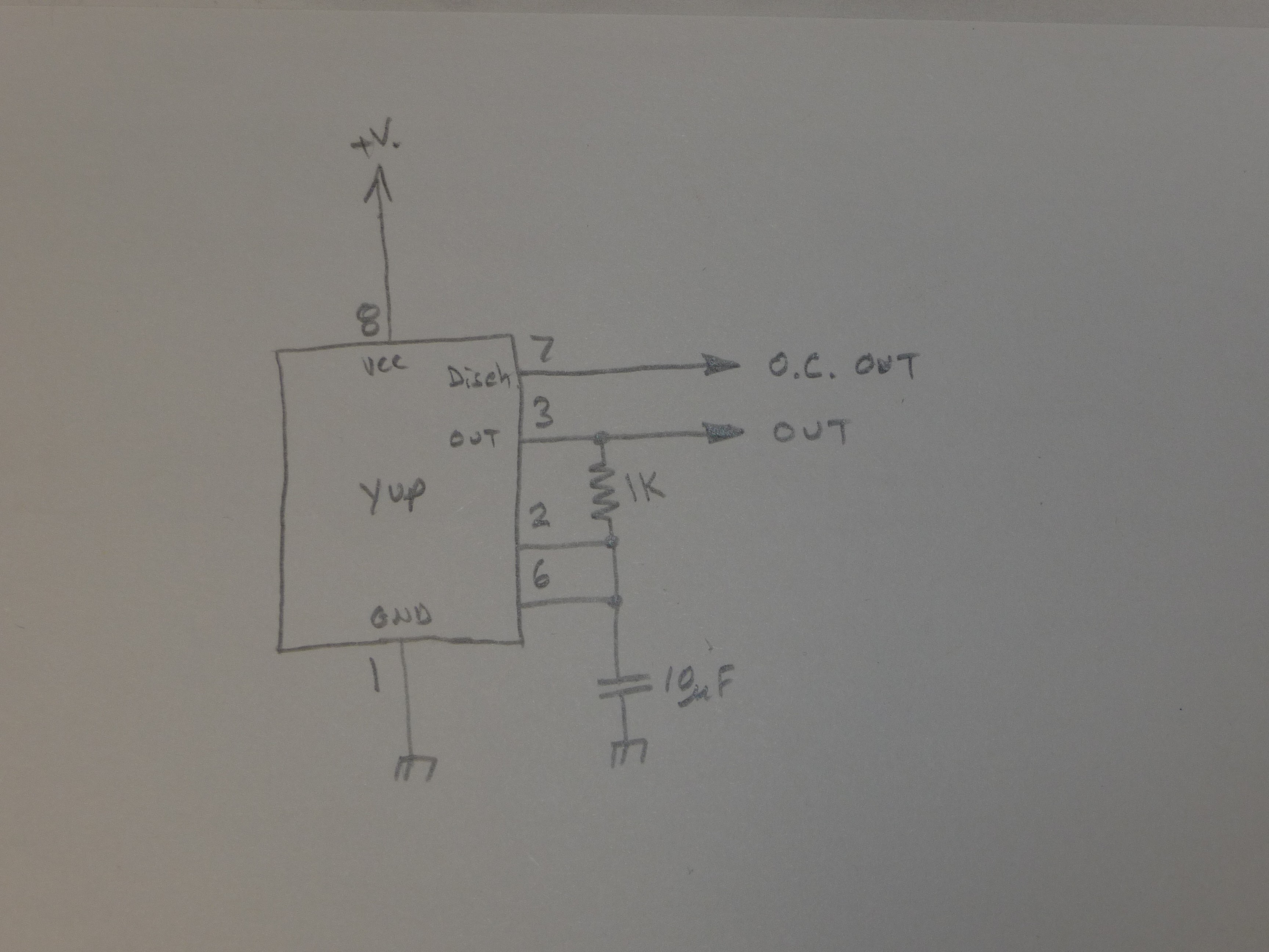
If you only want an output that is open collector (drive a relay, or LED!) , pin 7 is your friend! Pin 3 can still be used as a digital output.
That circuit is the one I almost always use for a 555. its duty is <close to> 50% and, including the 555, its only 3 parts.
shame I'm still stuck with that pin 2,6 thing :/
Mohr wrong
Did you know a capacitor blocks DC offsets? so what? right? Well, your timing capacitor does not have to go to ground, it can go to ANY stable dc voltage. And in this circuit, we have 2 of those.
Just to be more wrong, lets move the timing capacitor to Vcc instead of ground.

There is another thing we can do, we can turn the circuit into a 2 wire flasher (kinda)
How? WELL, The CMOS version of the 555 (yea, add that wire back to pin 4) consumes only TINY amounts of operation current. unlike the current needed to charge that big timing capacitor (use a big one!) So, using that we can make an oscillator that draws pulses of current.

[abrupt end of article, but actually, in fact, the end. Have a nice day, BYE!]
Discussions
Become a Hackaday.io Member
Create an account to leave a comment. Already have an account? Log In.