 teardownit
How is the generator connected? How to choose the right type of receiver probe? How to provide a probing current in the line being traced? What affects the range of the locator?
A thorough knowledge of all the techniques of working with the device, of course, does not guarantee error-free results (statistics show that even a very experienced operator during the day can make 10 to 20% of the errors in the total amount of work), but it can reduce the number of miscalculations.
The main tasks that can be solved by the cable locator :
- Determination of the cable route (cable bundles) and cable ducts;
- Identification of cable lines in a bundle or cable ducts, among others running in parallel;
- Identification of cable terminations;
- Cable core identification.
Solving each of these problems may require an individual approach - it all depends on the type of line being traced (twisted pair cable, coaxial, power, cable duct, pipeline), its characteristics (cross-section, frequency properties, length), its location (on the surface, in a cavity or in the body of a monolithic building structure, in the ground), as well as the characteristics of the generator and receiver available. Therefore, giving a set of direct and unambiguous instructions is impossible. A system of preferences, however, can be described.
First, you must determine the most effective sensor type for the case in question (coil or capacitive antenna) and the method of signal delivery (direct connection or inductive method).
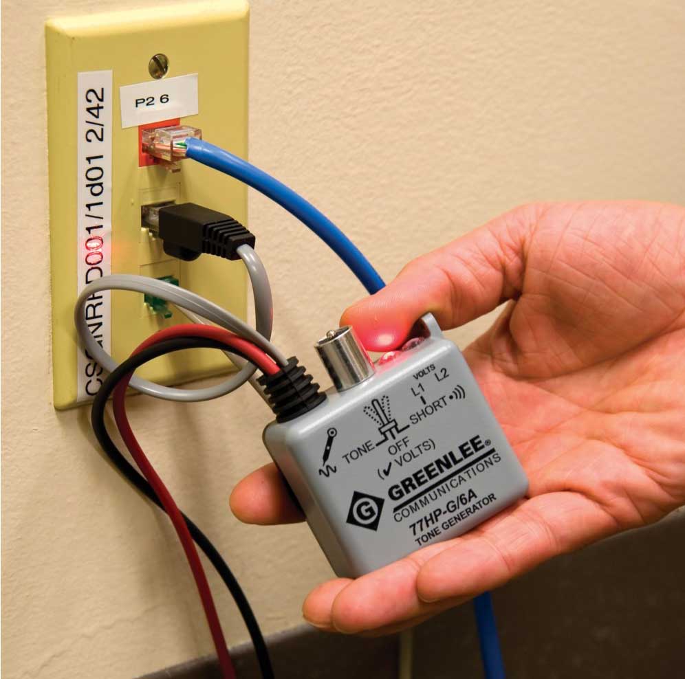
Direct connection involves physically connecting the transmitter to the line you are looking for, which requires access to either the cable strands or the surface of the conduit (conduit), and provides a rich selection of signal circuitry. In addition, it provides the most powerful signal applied precisely to the desired circuit. Therefore, if direct connection is possible, it should be preferred. The exception to this is when the line is energized. Although the transmitter output is normally protected against AC voltage up to 120 V, it is not advisable to connect it to live cable conductors. In this situation, an inductive coupler or inductive antenna is better suited.
An inductive sensor offers much greater capabilities than a capacitive sensor. However, to use a coil, the signal must be applied to a closed circuit through which sufficient current can flow for the available receiver sensitivity.

If we are talking about two conductors of a cable (a pair of cores or a core and a shield), there are only two cases where such a circuit can be arranged. First, if the remote end of the circuit is accessible and the conductors to which the signal is applied can be shorted. Second, if it is loaded (for example, the conductors are connected to a load or to the input circuits of some equipment). This also applies to pairs of conductors shorted due to reduced insulation resistance.
A closed circuit can also be arranged with a single conductor (core, shielding, metal armor, or a central supporting element of the cable, a conductive cable duct). This requires that it be connected to an earth bar at the remote end. This method is only suitable for lines within the same building (structured cabling, fire alarm, and power supply) because the generator must be connected to the same conductor and ground busbar.
It is crucial to understand that the range over which the receiver will be able to detect the signal depends to a large extent on the purpose and design of the cable. Since one of the goals of most cable designs (especially high-frequency cables) is to minimize the emission of the transmitted signal, selecting the conductors to which the signal will be fed must be made with great care. Tracing cables in a shield or protective covering (sleeve, wire, or foil braid) is possible because they do not eliminate the magnetic field completely. The signal is much more attenuated in cables armored with a steel tape or wire. It is almost entirely blocked by cable ducts made of steel or aluminum tubes. Therefore, such lines can be traced only by applying a signal to the channels themselves or by accessing the cable in the transition and junction boxes.
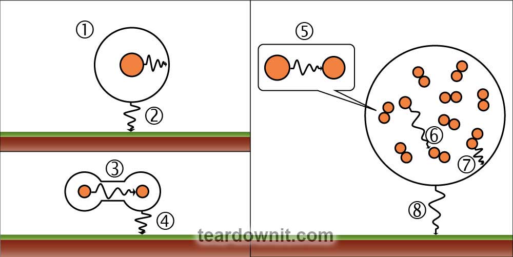
The last option to feed a signal into a traced cable by direct connection is to connect the generator to a conductor of the buried cable. In this case, the circuit can be shorted through capacitive leaks to the ground since AC voltage is used as the signal. There is no need to ground the remote end. However, connecting the transmitter to a conductor inside the cable (wire, shield, metal armor, or a central carrier) minimizes the effect of current leakage or signal transfer to nearby objects. For example, coaxial cable with an insulated shield and multipair telephone cable in polyethylene sheath is traced to a greater range than a twisted power cable and multipair telephone cable in the lead. The range is also affected by water in the conduits where the traced cable passes. Remember that a short cable section may not have the capacitive leakage present to provide enough current for the available receiver sensitivity. Then there is only one solution: ground the remote end of the line or switch to a high-frequency signal.
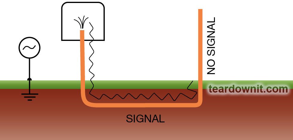
Grounding is also necessary if the cable comes out of the ground (e.g. when arranging an entry into a building). Suppose such a cable section is not grounded at the remote end, starting from where it left the ground. In that case, it will not be possible to trace the line - the current will not flow further because the capacitive connection with the ground will disappear.
When the ground is used as a return conductor, the generator should be placed close to the connection point to the cable. The path of the return current through the ground affects the total field (the magnetic fields of two conductors with different current directions are subtracted), so the grounding point of the generator should not be close to the cable connection point. The metal ground pin used in this case is buried in the ground at a small distance (15-30 ft) to the side and forward in the direction of the cable routing.
Discussions
Become a Hackaday.io Member
Create an account to leave a comment. Already have an account? Log In.