 teardownit
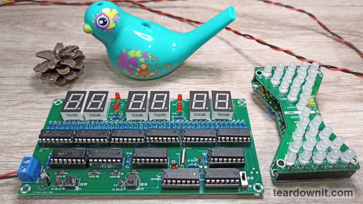
An electronic clock without a microcontroller is a circuitry masterpiece that can be looked at forever! Today we continue to explore the practical possibilities of pure logic.
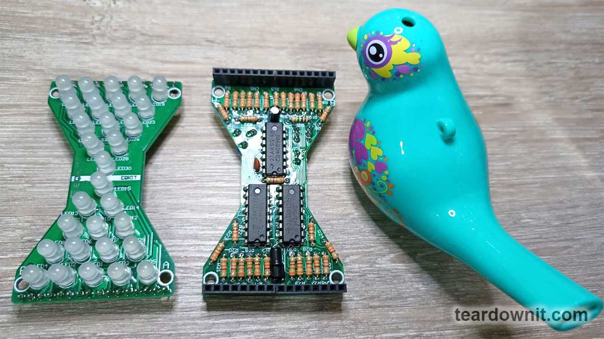
We start with an hourglass on the shift registers. Look what a beautiful design in a two-board stack! The top board has only the LEDs, and the bottom has all the chips and other components.

Any digital circuit starts with a clock. Instead of the apparent 555 timer solution, the circuit designers used the CD4069. It contains six logic inverters, of which only two are used, and the other four are idle.
The generator works as follows. There is almost no current through the U1 pin 1 and 3 because they are high-impedance inputs, almost like an operational amplifier. To make input 1 even more high-impedance and thus negate the effect of its current, the developers added a resistor R31.
The time-setting circuit, consisting of capacitor C1, resistor R32, and trimmer VR1, is constantly overcharged. Because it is connected between the input and output of the inverter U1B. More precisely, the capacitor is recharged through the series-connected resistors.
And an inverter is an inverter so that the logic level on its output is the opposite of the level on the input: one if the input is zero, and vice versa, zero when the input is one.
Ask, how is the capacitor recharged between the output and the input of the inverter? Did we just write that there is practically no current through the input? - Exactly right, but the current goes through the output U1A - the second pin of the chip.
When logic 0 is on pin 1, logic 1 will be on pin 2 and, therefore, on pin 3. And on pin 4 will be a logical 0. So the plus pin of C1 will be on the circuit's ground, and the minus pin will be charged through the resistors to the plus of the power supply.
That is precisely right. This is bad and wrong for an oxide electrolytic capacitor, and a solid device would have put a non-polar capacitor in C1's place. But in this toy, the developers decided that this would do.
Personally, my hourglass hasn't failed yet, but I don't turn it on for a long time. And if the capacitor still goes terribly, I will replace it with a non-polar one. The microcircuit won't burn out from the capacitor breakdown because it is charged and discharged through resistors. The clock generator will stop working, and accordingly, the sand in the LED lights will stop falling.
As soon as the capacitor is so charged, its minus terminal, connected through resistor R31 to input U1A, shows a logical 1, the second, and, therefore, the third pin of the chip will switch to low and the fourth to high.
The capacitor will start to charge in its correct polarity (while restoring the parts of the aluminum oxide layer that are corrupted by the wrong polarity) until pin 1 receives a logical 0, and everything repeats.
The time of this process, and therefore the clock frequency of the circuit, depends on what resistance the trimmer is set to. The limiting resistor R32 does not allow make the circuit resistance to zero.
The remaining LED control circuit consists of four identical nodes, each on a 4-bit shift register. One CD4015 chip contains two such registers. In total, two such chips are used.
The static shift register has a serial input and a parallel output. This means you can enter data - logical zeros and ones - in series on one wire leading to the D - Data input.
And this logic level will go from input D to output Q1, from Q1 to Q2, from Q2 to Q3, and from Q3 to Q4 when a clocking or synchronizing pulse comes to input CP.
Thanks to this memory circuit, you can light and extinguish almost any number of LEDs using just two pins of the microcontroller or just two wires or two radio control frequencies. Instead of LEDs, there can be relays, vehicle model servos, or something else just as enjoyable.
In the case of LEDs or light bulbs, this circuitry solution is called serial bus-driven static indication. It has long been successfully used in illuminated advertising and signage.
The running line and LED display were embodied in such a way even before the appearance of addressable LEDs and specialized controllers. Data and clocking signals could be taken from a personal computer's LPT or COM port by writing a corresponding program, which would alternate zeros and ones correctly.
The disadvantage of this solution is the low data transfer rate. Still, the crawl line is not an obstacle because the letters must run slowly so that people have time to read them. And the toy hourglass didn't even need a microcontroller. The shift registers do everything themselves. How exactly, we'll see.
Remember we made an electronic lock? It is based on 4 synchronous D-triggers connected in series. Together they make up just such a 4-bit static shift register with a serial input and a parallel output like in the CD4015 chip.
For the hourglass, one CD4015 chip replaces four CD4013 chips because CD4013 has two triggers, and CD4015 has two shift registers, each with four triggers.
But to create a lock (or even two locks), the CD4015 will not work. After all, each of the two shift registers of the CD4015 has a standard clock input for all four triggers. And the operation of the lock is based on the fact that each trigger's clock input is connected to its own separate secret button.
The first shift register receives data from the tilt sensor, a metal tube with one or two balls placed inside. A plastic insulator and a center pin are also insulated from the housing.
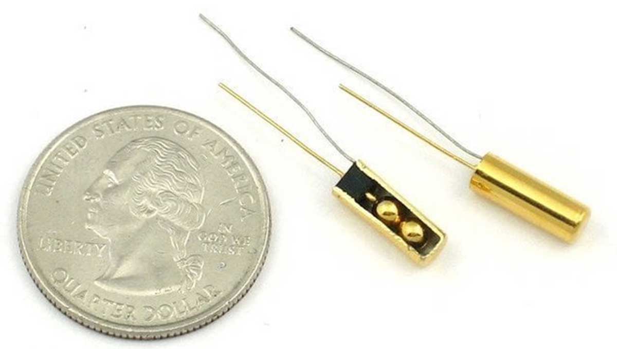
The ball closes the circuit in a vertical position with the pins facing down. In contrast, it opens the circuit in a tilted or upside-down position. Because of this, the circuit "knows" which position the printed circuit board is in.
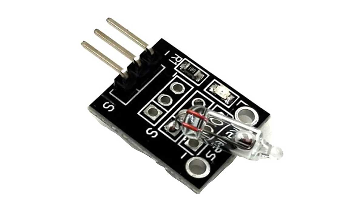
There is also a version of the tilt sensor with a drop of mercury instead of metal balls. It resembles a neon bulb. But this is not our case. Mercury switches are used where more excellent reliability is required, and the possibility of ball jamming must be eliminated.
So, the data input of the first shift register U2B receives a logical 1 if the hourglass is upright and a logical 0 if it is tilted or inverted.
With each clock pulse, the shift register outputs will be sequentially filled with 1s or 0s, depending on the position of the device in the planet's gravitational field.
From the fourth output U2B the data go to input U2A, and so on, to the third and fourth shift register. The result is one big 16-bit register.
Its last, 16th digit is unused, and the first 15 are connected to the LEDs through resistors. At a logical zero on the corresponding output, the LED of the upper group D1-D15 will light up, and at one, the LED of the lower group D16-D30 will light up.
This creates the visual effect of grains of sand flowing from top to bottom. One LED at the top goes out, and one LED at the bottom goes on instead. And so on until all the virtual sand flows over. Next, the clock will wait to be flipped over.
And now the digital clock!
Clocks with digital indication are much more complicated because they require a quartz frequency stabilization and counting of seconds, then minutes, and finally hours. The binary code needs to be translated into Arabic numerals that we can understand, and the corresponding LED segments need to be illuminated.
Thanks to our trusty friends - digital chips - these complex tasks can be solved logically, beautifully, and even simpler if you understand how the electronic "mechanism" works.
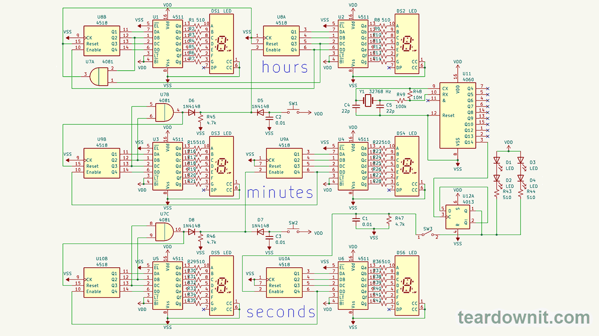
It all starts with the CD4060 chip. In the schematic, it is U11. It is a binary divider counter with a built-in oscillator, capable of operating in RC oscillator mode, similar to the inverter oscillator from our hourglasses, and also with a quartz resonator.
Quartz resonator Y1, we have a specialized clock for the frequency of 32768 hertz. 32768 is two to the fifteenth power. To get one pulse per second, the frequency of the quartz oscillator must be divided by two fifteen times.
The CD4060 chip "knows" how to divide the frequency into 16, 32, 64, 128, 256, 512, 1024, 4096, 8192 and 16384. Inside the chip is a division of 2, 4, 8, and 2048, but the developers did not have enough pins for them. :)))
32768 Hz / 16384 = 2 pulses per second. To get the 1 hertz we need, we divide the frequency in two again. The synchronous D-trigger U12A of the CD4013 chip will help us with this.
With this frequency, the dots between hours and minutes and minutes and seconds blink. The signal is then fed to the CD4518 chip.
This binary-decimal counter is designed to be paired with the CD4511 chip, translating the decimal digit into its corresponding LED indicator segments.
When the lower second digit has reached 9 and is reset to 0, it sends a signal to the next higher second digit. When it reaches 6 = 0110b, the AND logic element of the CD4081 chip, labeled U7C in the schematic, will receive 1's from the second and third binary digits and will, reset both seconds counters, and send a signal to the minutes counter, which is set up precisely the same way.
The clock counter differs only in that it is reset when you have counted to 24 and not to 60. 2 = 0010b, 4 = 0100b because the element AND U7A processes the signals from Q2 U8B and Q3 U8A.
And, of course, buttons are provided to set the hours and minutes and a switch to stop the clock and start it again when the seconds are synchronized with the reference time.
This clock has become my favorite homemade item, on a par with guitar pedals and radios, which are always visible, always on, counting down the time, and are a joy to look at decorating the room.
Demo video
Discussions
Become a Hackaday.io Member
Create an account to leave a comment. Already have an account? Log In.