 teardownit
To localize defects in metal cables, there is a popular, widely used device — reflectometer.

Photo from website TEMPO ® (www.tempocom.com/products/cablescout-cs90/)
The reflectometer measures the reflection of a signal. This method for cable damage detection complements all the others we've previously discussed and, in some cases, gives more accurate results, especially when locating wire entanglements or breaks and looking for non-persistent faults. Furthermore, it allows one to clearly identify several individual problems when they interfere with each other, as well as determine the range of each one of them.
Reflectometers' principle of operation
The reflectometer detects irregularities in any wire line (in particular, in a symmetrical twisted pair) by measuring the reflected signal. To do this, short DC electrical pulses are applied to the cable pair being tested. Suppose there is an imperfection in the cable. In that case, some or all of the energy of the original DC impulse is reflected back. Both the sent pulse and all of its reflections are shown on the display. Impedance abnormalities could be of various origins; each of them has a unique reflection pattern. Thanks to this feature, it is possible to determine from the shape of the reflected signal not only the location but also the nature of the fault.
This principle of determining the state of a cable pair based on the parameters of the reflected pulse is called time domain reflectometry (TDR). At its core, it is identical to the radar principle used in radio systems.
The method of measuring the signal at the output of the line being tested (also called the incident wave method) provides only an integral assessment of the line's condition. It requires two devices: a generator on the transmitting side and a signal meter on the receiving end. On the contrary, reflectometry, firstly, allows one to estimate the quality of the wire at any point of its length. Secondly, a measuring device is needed only at one end of the line. This latter feature is the key for TDReflectometers to become as widely used as they now are.
 To determine the distance to a particular fault spot or just an impedance abnormality of the cable, one needs to simply set the propagation coefficient and measuring range. The propagation coefficient defines the speed of the electrical impulse going through the cable of a particular type as a reference for the reflectometer. After capturing the impulse, the device will automatically calculate and display the distance to the damaged point of the cable.
Before looking into all the quirks and features of reflectometers, it is helpful to briefly describe the key features of a simple symmetrical twisted pair cable, as they are directly related to the reflectometer's operation.
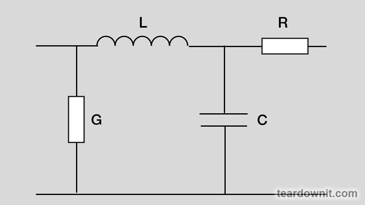
It is well known that any symmetrical pair is a two-wire electrical line, and it is described as a chain of primary sections connected in series. Each section is a simple circuit, a four-pole unit consisting of active resistance R, inductance L, capacitance C, and active conductivity G.
 When a harmonic signal circulates in a twisted pair circuit, the voltage-to-current ratio at each point is called the input impedance of the twisted pair. If a twisted pair is loaded at the end with a resistance equal to
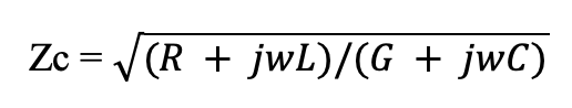
where w=2pf, then it's input resistance will be equal to Zc anywhere along the line.
This input resistance for any twisted pair is its defining feature, and it is called wave impedance or characteristic impedance. In this ideal example, all the energy of the signal, when reaching the load Zc, dissipates completely from it. This characteristic is relevant for a specific cable length known as electrical length and listed in a spec sheet.
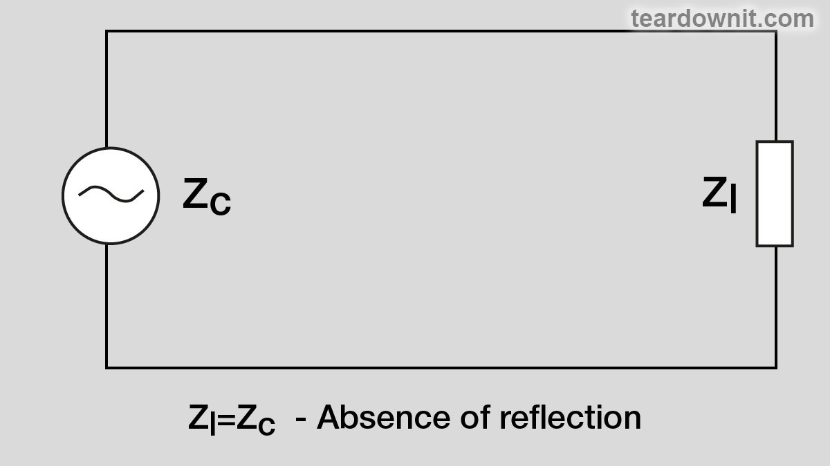
Suppose a twisted pair is loaded with a resistance ZL different from Zc. In that case, the energy of the probing signal is only partially absorbed by the load and partly directed back to the emitter. The relative measure of the power going back through the line is called the reflection coefficient, p = (ZL – Zc)/ (ZL + Zc).
If ZL = Zc, then this reflection coefficient is equal to zero, meaning there's no reflection at all, and this is called "impedance matching."
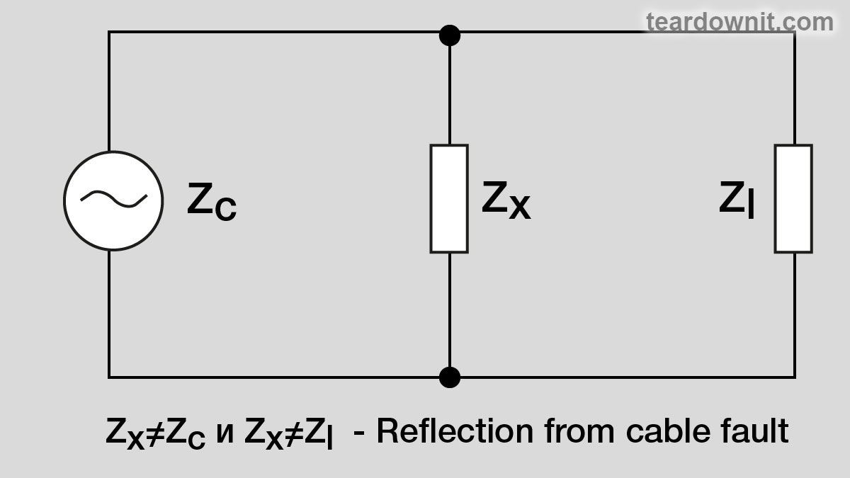
If there is an imperfection somewhere at the point "x" (Zx< >Zc), the reflection coefficient
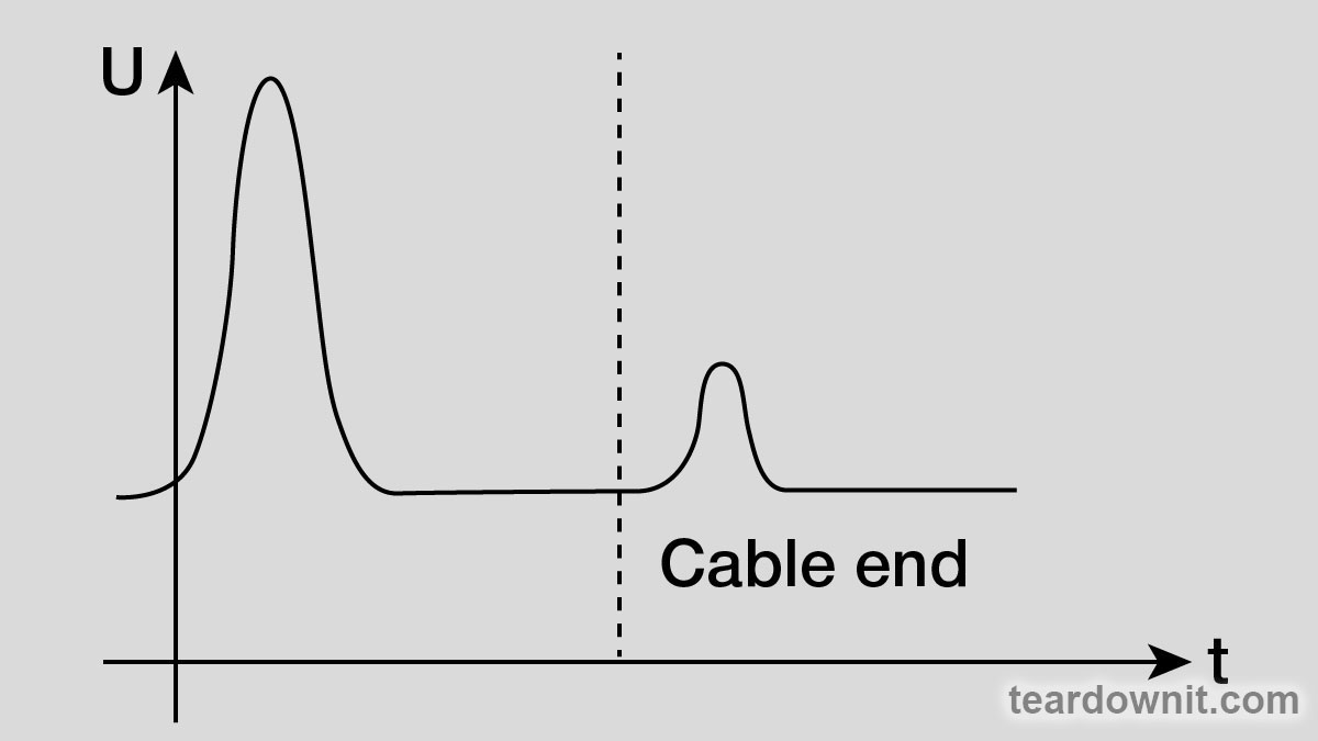
p = (Zx - Zc)/(Zx + Zc) will have a non-zero value, meaning there's some reflection of the initial impulse. There could be two edge cases: a short circuit or an open circuit.
Open circuit means wire breakage, and Zx is infinitely big.
In this case, the probing signal is reflected back from the breakage completely, keeping the original phase and polarity when detected by the reflectometer's receiver.
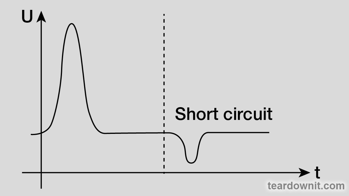
If the line is shorted at the point X, then Zx=0. Thus р = (0 - Zc)/(0 + Zc) = –Zc/+Zc = –1. The probing impulse will also be completely reflected back by the short circuit point, but its phase will turn 180 degrees, so we'll detect reverse signal polarity at the reflectometer's input.
For all the other intermediate conditions of the twisted pair, like a partial circuit shortage or opening, the image is more complex. Usually, interpreting this takes some professional experience, but it can be viewed as a set of standard known faults in a cable.
The precision of finding a faulty spot in the cable depends solely on the predefined speed of signal transmission.
Electromagnetic energy travels along the symmetrical pair with a predefined finite speed, which depends on cable specs and signal frequency. Ideally, the speed of signal propagation in a cable is V=w/b, where w=2pf and b is a phase coefficient, a function of twisted pair parameters. V speed increases with increasing frequency, never exceeding the speed of light.
The quantitative measure of the speed of propagation is the VoP factor (Velocity of Propagation); its numerical value is a ratio of signal speed in an electrical circuit to the speed of light in a vacuum. The value of the VOP factor for a symmetrical pair is determined by the diameter of the wire, the distance between the cores, and the type of dielectric; additionally, it depends on the ambient temperature and can change as the cable ages. The deviation of VOP from the spec sheet value is considered acceptable if it is no more than 3%.
Discussions
Become a Hackaday.io Member
Create an account to leave a comment. Already have an account? Log In.