 teardownit
The reflectometer's capabilities in terms of maximum distance and damage detection accuracy are determined by the sensitivity of the amplifier and some other important parameters.
Amplifier sensitivity
The sensitivity of the reflectometer, along with the pulse amplitude, is one of its most essential characteristics. It determines the maximum operating range of the device. It is crucial if you're going to check cables with high signal attenuation.
Technical documentation often skips this parameter or describes it very vaguely. In an ideal scenario, sensitivity should be characterized as the input voltage when the waveform on the instrument display is contained between the top and bottom edges of the screen (i.e., “x mV for full-screen deviation”).
Vertical sensitivity is sometimes measured in decibels. The decibel value is relative and has no meaning unless given a reference level of 0 dB. With this data, the amplifier's sensitivity can be calculated, as each 6 dB step doubles the gain.
Based on the parameters mentioned above—pulse amplitude and amplifier sensitivity—it is possible to calculate the maximum overlapped line attenuation, which also serves as a criterion for assessing the quality of TDR.
The maximum overlapped attenuation (amax) is defined as the line attenuation when the deviation of the vertical beam is at least one-eighth of the full screen. In this case, amax is calculated using the formula:
Amax = 20 lg8 + 20 lg(Upuls/ampl),
- Amax is the maximum attenuation,
- Upuls — pulse amplitude under load Zo,
- Vampl — amplifier sensitivity for full-screen deviation.
It should be mentioned that this method can only be used to compare reflectometers from different manufacturers. It will be impossible to accurately calculate the maximum attenuation overlapped by the reflectometer using this method since the attenuation in metal cables is frequency-dependent. Therefore, different duration pulses will correspond to different Amax values.
The covered method for estimating overlapped attenuation better suits optical TDRs. Optical fibers have frequency-independent attenuation, and therefore, in optical time domain reflectometers (OTDR), the pulse amplitude and sensitivity of the photodetector are usually not taken into account; they are "integral" parameters of the device. A parameter called "dynamic range" is introduced instead, i.e., the insertion loss of the line, at which the signal-to-noise ratio SNR = 1 for a certain duration of the probing pulse. To widen the dynamic range of OTDR, one needs an increase in probing pulse power and the receiver's sensitivity, as well as a very specific set of digital processing algorithms developed by the manufacturer.
Resolution and accuracy
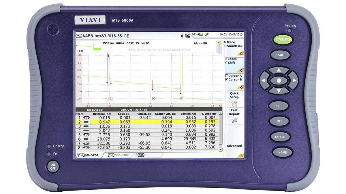
[illustration from viavisolutions.com]
Before discussing the issues related to resolution and accuracy, some basic concepts should be defined.
Display resolution is the interval between two consecutive dots on the screen.
Fault detection resolution is the minimum distance between two consecutive faults to be visible as separate faults on the reflectometer display.
Sampling precision is just the precision with which samples are carried out.
The term "fault localization precision" also speaks for itself.
Fault localization precision
The accuracy of finding the fault in the vast majority of real-world cases is limited by the availability of reliable information for the cable being tested and not by the sampling precision or display resolution of the reflectometer.
Firstly, the pulse propagation coefficient can only be known with an accuracy of a few percent, and on top of that, it is affected by temperature changes. A 1% error in setting the pulse propagation coefficient leads to a 1% error in determining the distance.
Secondly, the limited information on the actual cable route, in turn, limits the user’s ability to find a point along the cable trace marked by the reflectometer as the location of the fault. After all, when tracing a cable to localize the damaged spot, it is nearly impossible to account for all the peculiarities like safety loops, different laying levels, specific terrain, etc.
The resolution of fault detection is also influenced by the pulse duration.
Sampling precision and display resolution
Sampling precision and display resolution are not the same thing. The device may have a high level of sampling accuracy, but its display may have poor resolution, and vice versa.
For example, consider a device with a display resolution of 100 ns. It can detect damage with an accuracy of +100 ns, regardless of the precision of the sampling generation every 100 ns. Similarly, the device may have a display with a very high resolution (say 0.1 ns). Still, if the sampling precision is insufficient, then in this case, it won't be possible to accurately determine the location of the fault. One should remember that when searching for a fault location with a reflectometer, high display resolution, and sampling precision are not always necessary. Even if the reflectometer allows one to find the damage locations within 1 cm, due to the cable routing environment, this level of accuracy is not enough for fault localization; you simply won't be able to find them on a real cable. Thanks to modern clock generation techniques, many OTDRs have sufficient accuracy and resolution of sampling that they can be used in most real-world applications.
A few other important characteristics are tied to the parameters we've covered. We are talking about measurement limits (maximum and minimum distance) and the possibility of scale adjustment.
Maximum distance
Modern technologies make it easy for manufacturers to achieve an almost unlimited range for their devices. However, the sensitivity of the device does not guarantee actual detection of damage at the specified maximum distance. The best way to determine the range of a device is to test it with a cable. The OTDR's distance measurement range and cable length should be gradually increased until a critical point is reached, i.e., a state when the OTDR cannot detect the open end of the cable. When comparing different reflectometers in such a way, it is necessary to use pulses of the same duration.
Minimum distance
Suppose a minimum operating distance of 10 m is specified for one device and 20 m for another. In that case, one shouldn't immediately jump to conclusions. Both devices likely have the same display resolution. Still, the second one has a physically larger display or is less capable of adjusting to the same resolution. Therefore, the key characteristic is the minimum display resolution, not the minimum working distance.
Scaling
Some manufacturers include a scaling function in their reflectometers, allowing them to increase the display's resolution at any distance. In practice, this function has certain limitations when testing long cables. The reflected pulse tends to be "stretched", which leads to losing all advantages in locating the exact point of failure. Typically, only scaling levels no higher than 4× or 8× make practical sense.
Discussions
Become a Hackaday.io Member
Create an account to leave a comment. Already have an account? Log In.