 Mirko
MirkoWith this tutorial I want to show you how easy it is to setup your own Open Thread Border Router at Home using a Raspberry Pi an nRF52840 USB Dongle and connecting the open source Thread Sensor Tag to measure Light, Temperature, Pressure and Humidity with ultra low power
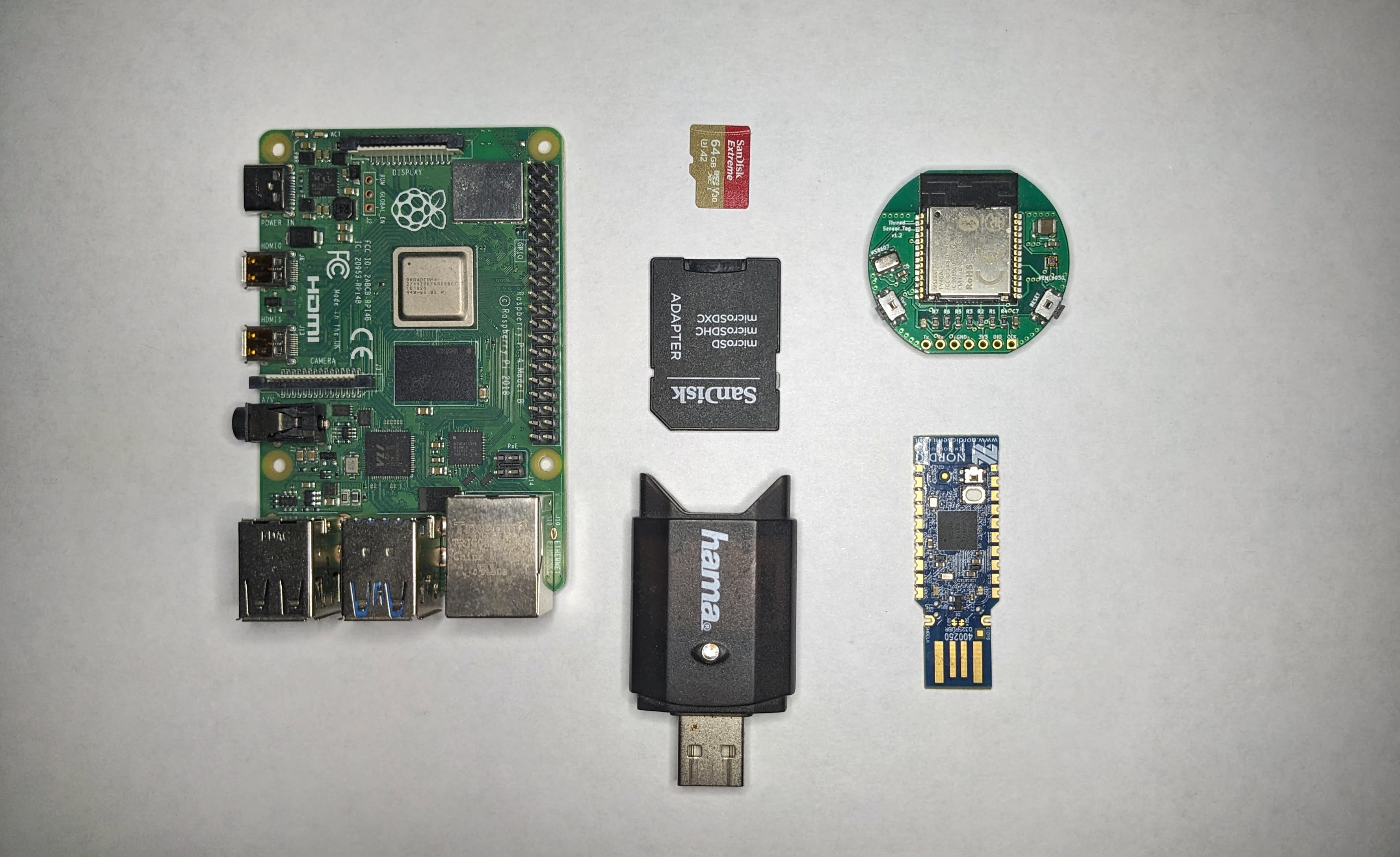
Components you need are
- a Raspberry Pi 4
- an SD-Card
- the nRF52840 USB Dongle from nordic
- and the Thread Sensor Tag
Step 1: Flash the Raspberry Pi OS to the SD-Card
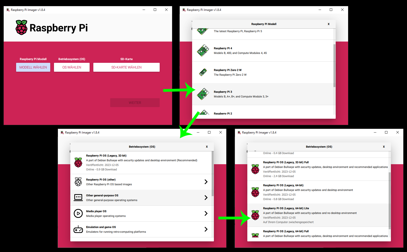
Use the Raspberry Pi Imager to flash the Raspberry Pi OS onto the SD-Card.
- Attach your SD-Card to your computer
- open the Raspberry Pi Imager and select the Rasperry Pi device you want to flash the SD-Card for (Recommended is a Raspberry Pi 3B+ or later. I am using a Raspberry Pi 4)
- Then you select the OS: "select OS" -> "Raspberry Pi OS (other)" -> Raspberry Pi OS (Legacy, 64-Bit) Lite
- choose the SD-Card and press next.
I recommend to add pre-defined settings like your WiFi and SSH etc.
Step 2: Flash NRF52840 RCP Firmware
Make sure you have the nrfurils installed.
- Attach the nRF52840 USB Dongle to your computer and press the reset button to bring it into the DFU Boot mode.
- Download the Firmware ZIP file and run the following command to flash the nRF52840 USB Dongle
nrfutil dfu usb-serial -pkg build/bin/ot-rcp.zip -p /dev/ttyACM0
If you want to build the latest version of the firmware yourself you can follow the official nordic guide
Step 3: Install and Setup the Open Thread Border Router Software
In order to run the Open Thread Border Router on the Raspberry Pi we need to download and install the Open Thread Border Router repository. Run:
git clone https://github.com/openthread/ot-br-posixcd ot-br-posixWEB_GUI=1 ./script/bootstrapINFRA_IF_NAME=wlan0 WEB_GUI=1 ./script/setup
to clone the repo, go into the folder, executing the bootstrap script with WEB_GUI enabled and then setup the otbr.
I tried to use Docker as well but with Docker I was unable to receive the UDP Pakets from the Thread Sensor Tag.
After this is done I recommend rebooting the Pi. After rebooting you should be able to reach the Border Router Web GUI by typing its IP Address into the web browser like http://192.168.178.xx
For troubleshooting and more information you can find the official instructions here
Step 4: Setup the OpenThread Network
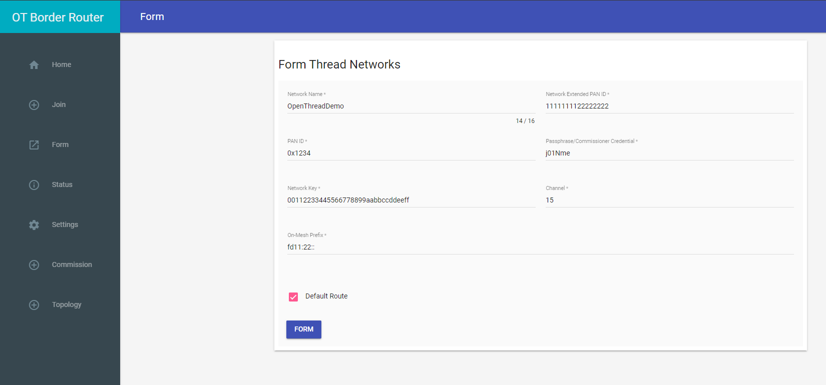
Open your browser and enter the IP address of your Raspberry Pi like http://192.168.178.XX make sure you use the correct IP Address. If you set a host you can also type the host name.
In the OTBR GUI go to the Menu "Form" to form a new Thread Network. You can leave the fields as they are for now but Google recommends to change them and leaving the default Channel and On-Mesh Prefix values. Then press Form
Step 5: Connect the Thread Sensor Tag to the Thread Network
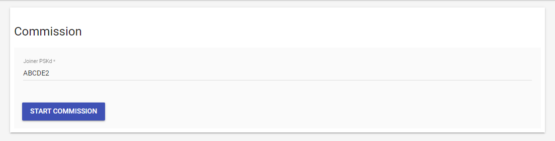
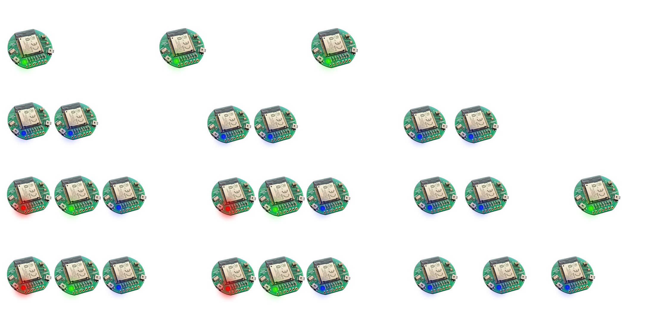
Place a Battery into the Thread Sensor Tag and check the LED, it will blink red -> green -> blue and then just blue two times to show that it is there but has no network. (see the Troubleshoot section to know more about the blink patterns)
In the OTBR GUI go to the Commission Menu entry. You will see a text field which is asking for the Joiner PSKd. The Thread Sensor Tag comes with the default Joiner PSKd ABCDE4
Enter the PSKd and press Start Commission
Once this was done the GUI will promt you with a success Dialog and the Thread Sensor Tag will start blinking green once every 30 seconds which means it is happily connected and already sends its data into the Thread Network.
Step 6: Check the Data Incoming From the Thread Sensor Tag
Once the setup worked you can use socat to subscribe to the UDP port to receive the packets that the Thread Sensor Tag is sending. To do so first install socat on the Raspberry Pi by running
sudo apt-get install socat
and with the following command you can subscribe to the UDP Packet Stream of the Thread Sensor Tag
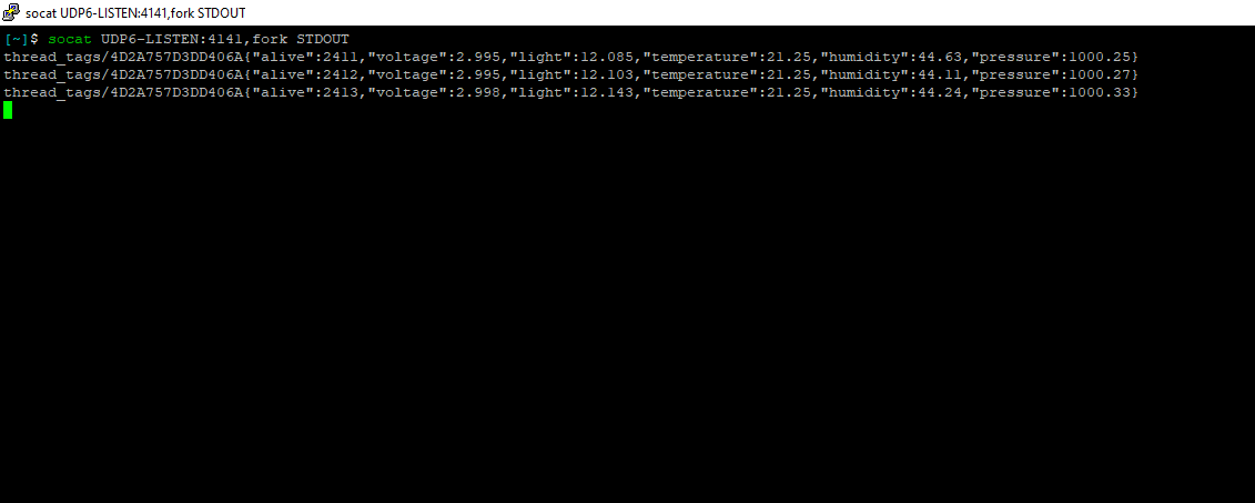
socat UDP6-LISTEN:4141,fork STDOUT
This command will print the UDP Packets received from the Thread Sensor Tag every 30s which will look like this
thread_tags/XXXX{"alive":2411,"voltage":2.995,"light":12.085,"temperature":21.25,"humidity":44.63,"pressure":1000.25}
where XXXX will be the unique ID of each device. The Thread Sensor Tag will measure the following data every 30 seconds:
- Alive: the ticks, how long the device is alive already. This value times 30 will give you the seconds of how long the device is already running
- Voltage: This Value shows the exact value of the Coin Cell battery. If it drops below a certain value it is time to maybe change the battery.
- Light: the measured Light Value in Lumen
- Temperature: the measured Temperature Value in C°
- Humidity: The measured Humidity Value in %
- Pressure: The measured Pressure value in Pa
You can run multiple devices in the same network and you can use tools like Home Assistant or node-red to translate this UDP pakets into meaningfull MQTT JSON messages or other usefull data formats to maybe save it into a database.
I will write other Tutorials showing how to do that as well late.
Troubleshooting
The Thread Sensor Tag is an open soruce ultra low power Sensor Tag which source you can find here
The Sensor is showing its current state using the on board RGB LED. See the image above for the blinking patterns the device can perform.
To do a factory reset you press the reset button and after the first hello signel (red,green,blue, and before the second helo signal) you press both button again for a quick boot. Once you see the hello signal press both buttons again. If you see the blue LED blinking 3 times, the device was factory reset.
Discussions
Become a Hackaday.io Member
Create an account to leave a comment. Already have an account? Log In.
It was commissioned correctly in the end. Thanks for the quick reply!
Are you sure? yes | no
you are welcome - if you have any other question do not hesitate to write me
Are you sure? yes | no
I do have another question. I posted it to github:
https://github.com/HomeSmartMesh/sdk-hsm-sensortag/issues/22
Are you sure? yes | no
after blue-blue-blue the factory reset was done - after that you should be able to re-commission the device into your network. Sometimes it might not work right away or it even takes a while to show green. But in general it should work (famous last words)
Are you sure? yes | no
Hi Mirko,
thank you for the tutorial!
I have one question about the factory reset.
I am following your instructions:
- press reset
- wait for red-green-blue
- press reset+sw1
- wait for red-green-blue
- press reset+sw1
after that I get blue-blue-blue, then red-green-blue, red-green-blue, blue-blue but no green. After about 60 sec I get red-red then red-green-blue again.
Am I doing something wrong?
Do you have any suggestions on how to proceed?
Best wishes,
Fede
Are you sure? yes | no