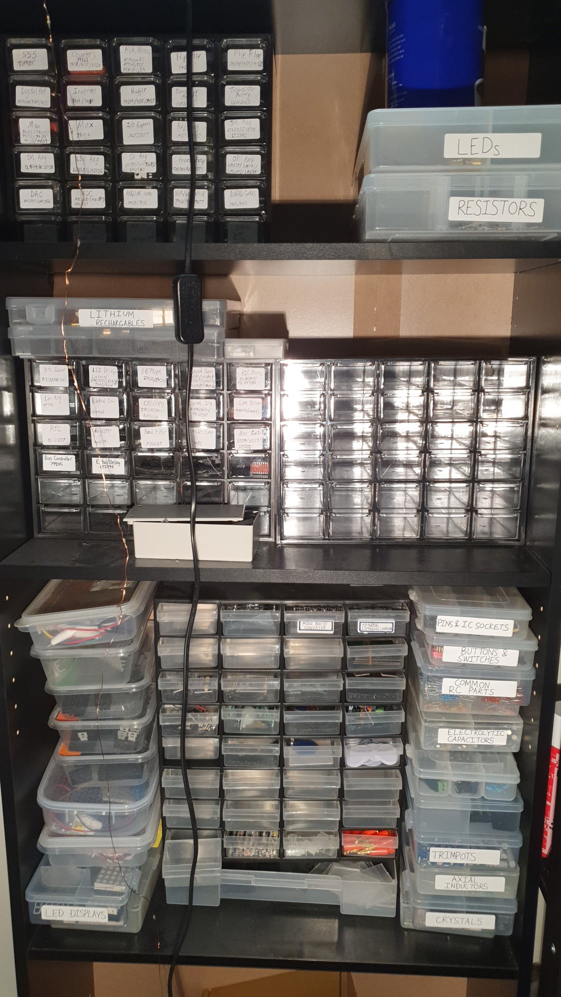
It can take a long time to find a list of them for a prototype.
This is just one cupboard:
So I've come up with a solution: transferring everything into draws and putting lights behind the draws that flash and tell you which draws to search.
I made a plan, involving an LED matrix with a thin controller board behind each draw:
This was to be supported by a component database connected to a local server with an easy-to-use database that's quick to add a lot of parts to.
I drew a UI mockup of it. I'll later put it together with Python and the ttkbootstrap library.
One of the guys at my local hackerspace told me the matrix added a lot of complexity and proposed a new plan. Neopixels (WS2812B LEDs) can be arranged in a diamond formation such that the outputs and inputs are connected to one another, then power bus bars can be run along the length of the cabinet.
I decided to give each unit its own daisy-chained connector so they can be disconnected and moved around.
I also made a variable to show the case and lid so they can be viewed together when designing but separated later to export them as separate 3D objects.
There's also space for a lithium rechargeable below the PCB.
Like this basically.
So this is definitely something that's going to work first time right?
Nope.
There's some nasty warping on that corner.
Is it because it printed directly on the bed?
Maybe I can just rotate it and add some autosupp...
You've got to be kidding me!
The supports are all there but this thing I was trying to print is not!
That's the last time I use the printer manufacturer's software to do auto-supports.
I redid it with Lychee slicer.
Well... the internal dimensions are good so that'll have to do for now.
That corner is turning out to be a real problem. I'll have to give the tray a good clean later.
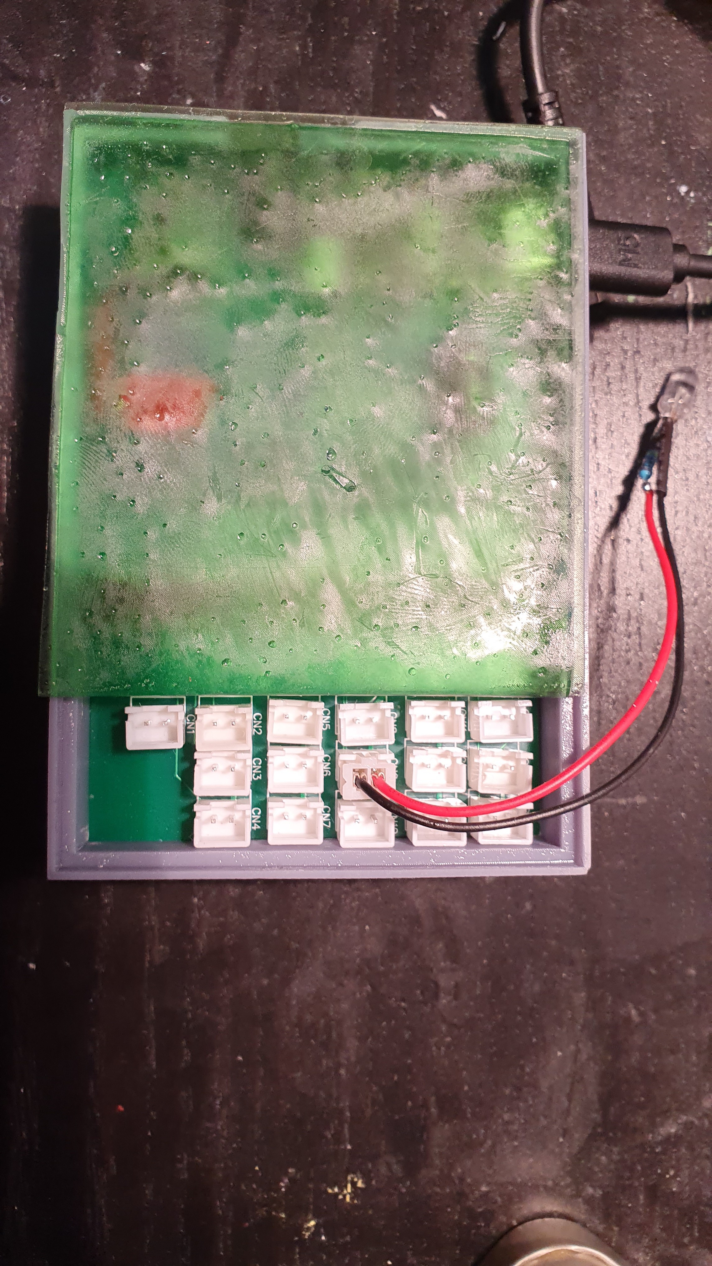
Pretty tight, but the board fits!
I also printed the lid in translucent green.
Note that it has a cutaway so the sixteen light connectors are accessible from the top.
Since I wasted so much time on 3d printing (and half a dozen other active projects) I haven't made much progress on the software so far, but stay tuned for more!
In the meantime, the v3 light controller will have to continue their work.
I don't think I've shown them before (I made them before my project documentation began) but here they are in all their perfboard glory:
Continuing on from last time my boards have arrived from JLC PCB.
Looks good!
I did a quick inspection for issues and some basic electrical tests to make sure the thing's not going to turn into a pile of melted plastic as soon as I plug in the DC jack.
No problems so far.
I started loading the components.
S
So far so good....
Oh. Crap.
So it turns out getting the version with the headers already installed was a pretty bad idea.
They're all on the wrong side!
Now I'll have to desolder 50+ pins per module.
Or will I?
After engaging my brain for I moment I realised that you can just flip the capacitor and terminals. then install the module upside down and all the pinout remains the same!
Well, I'll have to connect the terminals the opposite way around and the pin numbers are now flipped such that channel sixteen becomes channel one and visa-versa. But that's something fixable in software.
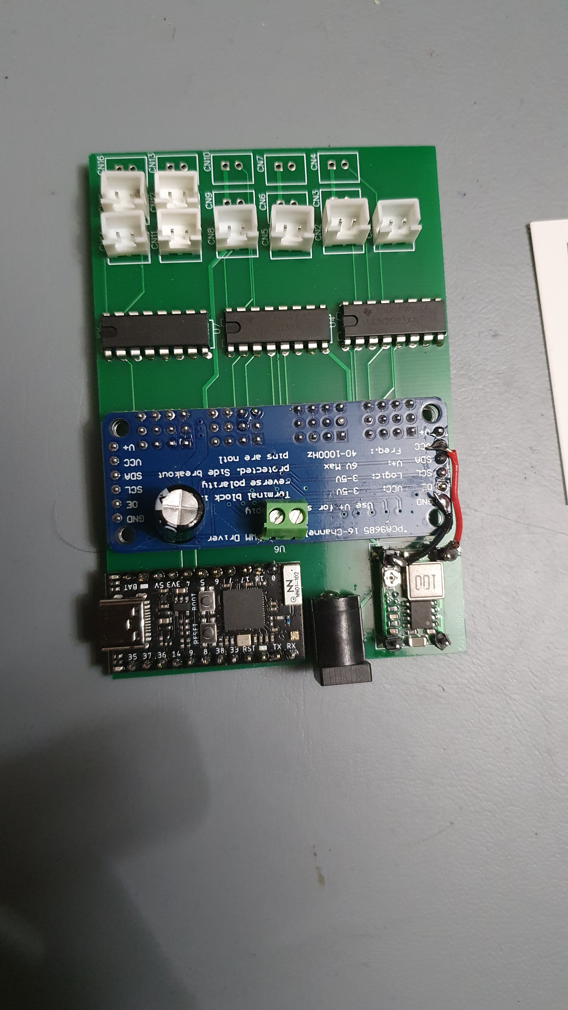
With this unorthodox modification, I finished the rest of the soldering:
Well, almost. Most of the connectors are still stuck in the Australia Post system, and my workshop supplies were surprisingly empty after using most of them for the v3 boards at the beginning of the year.
In the meantime, I connected up the board and built a little webserver in CircuitPython:
Yep, that's all of it. Easy stuff.
All it does is wait for a POST to /set, convert it to an int, and send it to the PWM controller.
Fortunately, Adafruit has a PCA9685 library for CircuitPython; because I'm not one to reinvent the wheel.
I made a little LED attachment to test it.
When the headers finally arrived I assembled the rest of it and started testing.
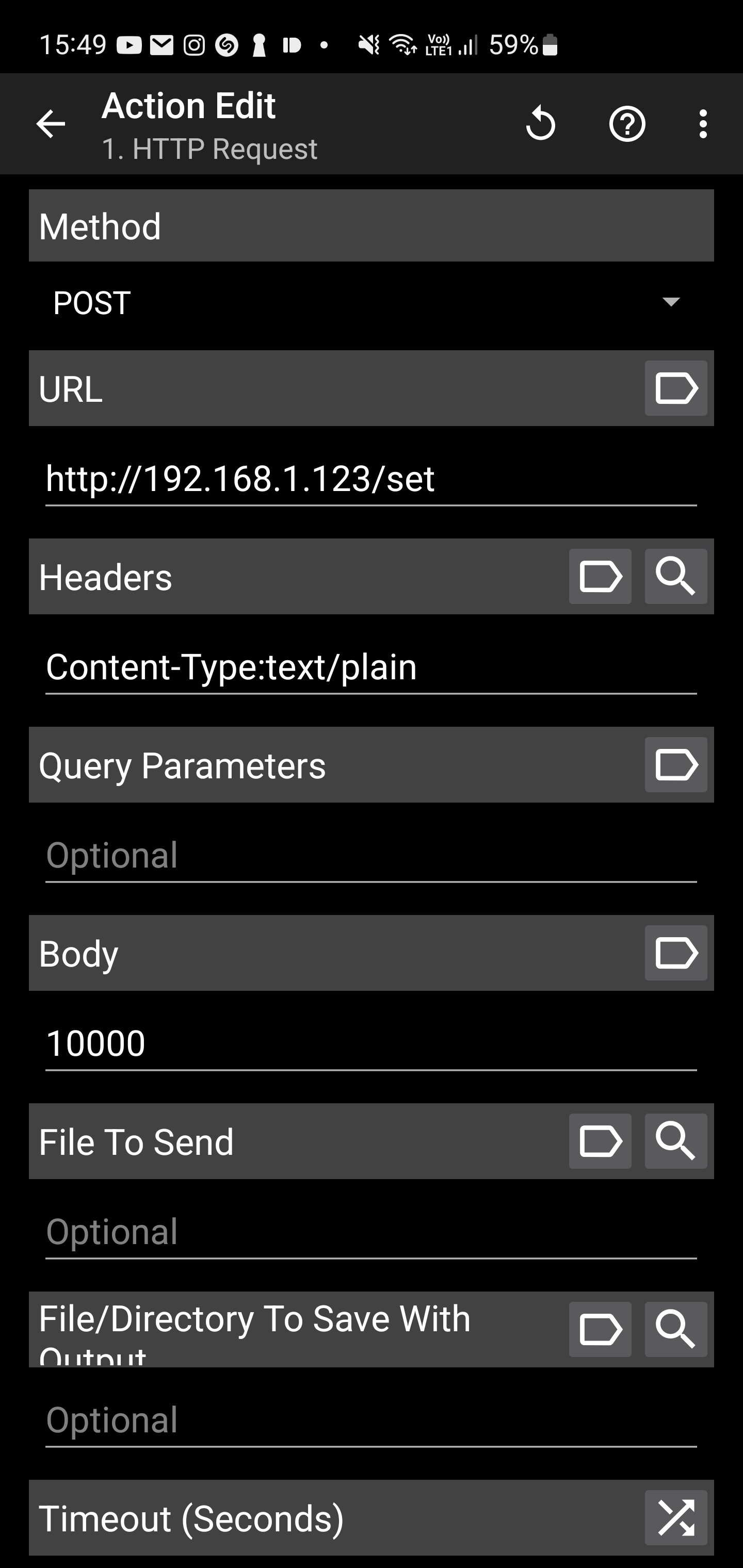
I tested it out with a POST action from the Tasker app on my Android device:
Seems to work okay and respond to changes in brightness.
But I need a better API that can set the value of specific channels.
So I jumped back to VSCode and wrote a simple JSON command system that lets you run on, off, and set commands with light number and brightness in the case of the light.
This is just to test it out, it's not the language that the actual controllers are using.
I sent a lot of requests to test it out:
(You can send multiple at the same time using the JSON array.)
Brightness seems to be adjusting okay and on/off is working. Very responsive.
I tested the other ports to make sure there were no unexpected surprises.
Join me next time as I put together a 3D-printed case and implement this archaic scripting code that I originally developed for the very memory-limited v1:
Not exactly well documented!
But all my light programs are already running it so I don't really want to change it.
Something I've been meaning to do for a while, creating a new version of my lighting controller to work with my home server and cut out external dependencies.
v1 - ATMEGA328P (Uno) + Ethernet + Android/Tasker
Works, but fairly unreliable and can't be set remotely.
Uses an external cloud service which simplifies a lot of the comms.
Looks messy, want to clean it up a lot.
Uses an ESP chip for the WiFi and an ATMEGA chip for running the real-time pattern code.
v3 - ESP32 (TinyS2) + Arduino Nano + 3D printed case + WiFi + Thinger.io
Much cleaner and integrated into a nice box.
I've got a new drive circuit and controller board and want to make a new version. Maybe order a proper PCB and integrate it with my home server.
Also, I'd like to accurately measure the box this time and get the 3D printing right.
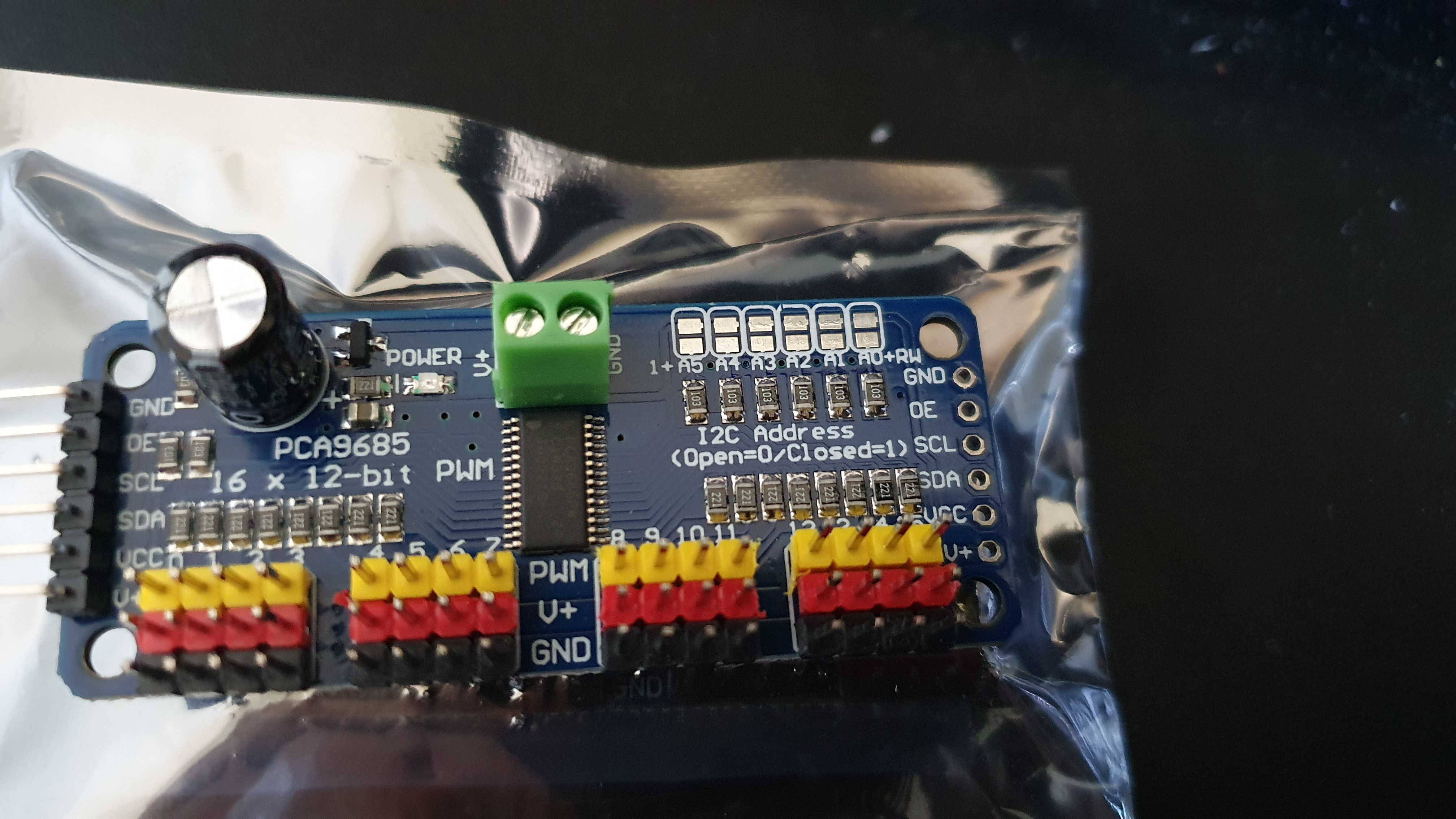
I've just got a few of these little PCA9685 PWM controllers:
That's 16 PWM outputs easily.
I want to remove the coprocessor, but that'll involve somehow keeping the code working in real time while keeping the WiFi responsive.
I'm guessing that's going to involve a mess of RTOS stuff, hopefully, that won't force me to write the whole thing in Espressif C rather than something nice like CircuitPython. Think of the valuable hours of my life I'd waste...
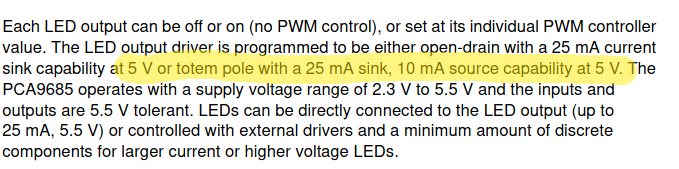
So I'm guessing I can't drive very much current directly off this chip...
No good, I want at least 100mA per channel. That was the limit for the previous version.
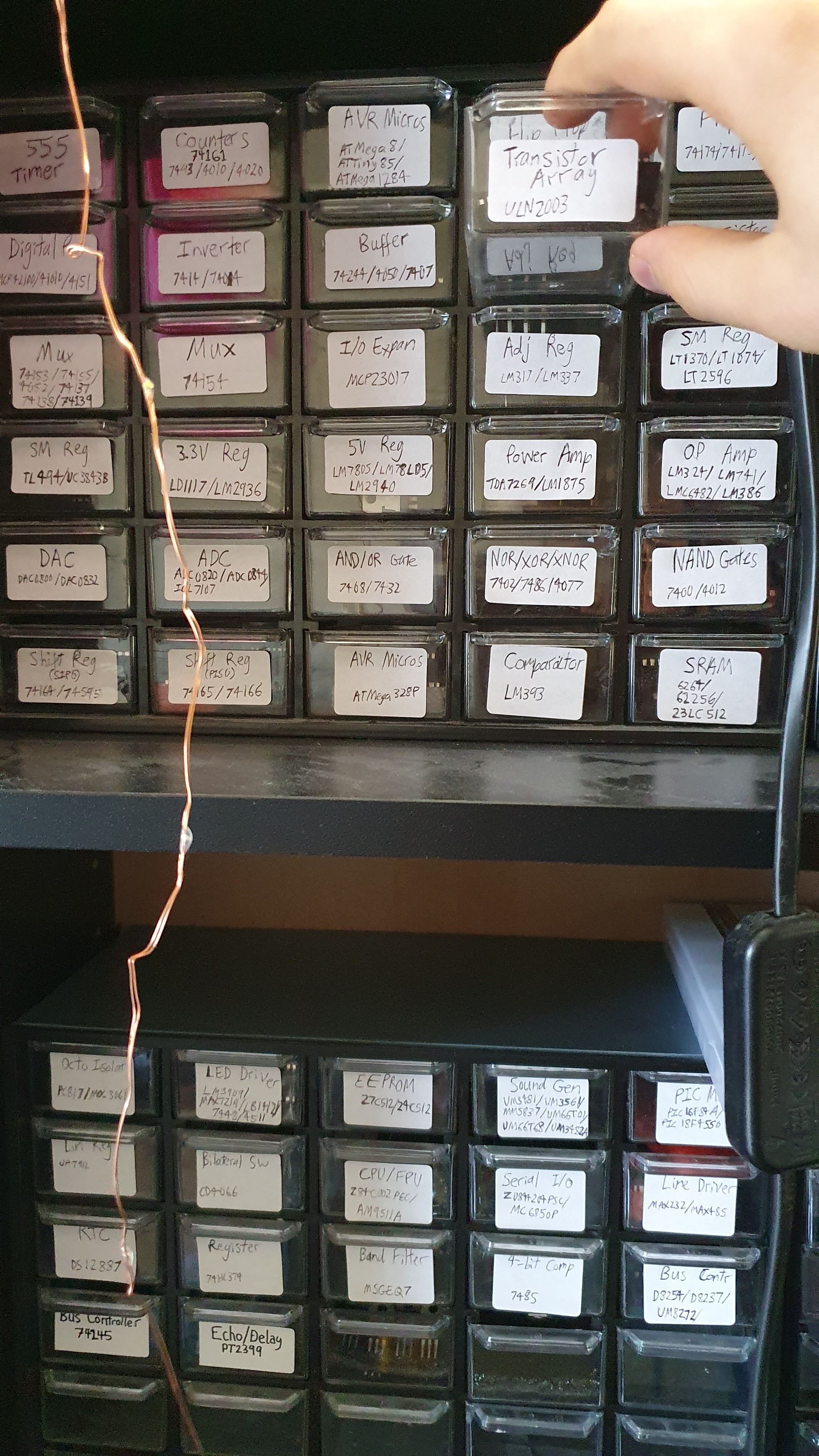
Let's see what I have in the workshop.
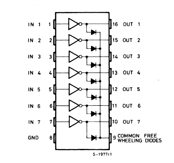
Ah, perfect.
Looks like that'll support the required 100mA per channel even with all channels running simultaneously and it should be very easy to wire.
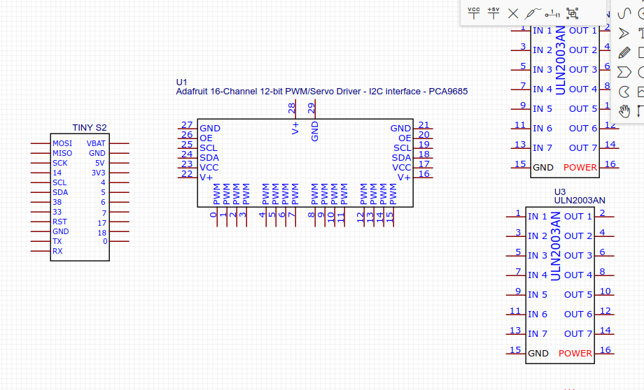
I'll add in a TinyS2 ESP32 module and draw up a schematic for that.
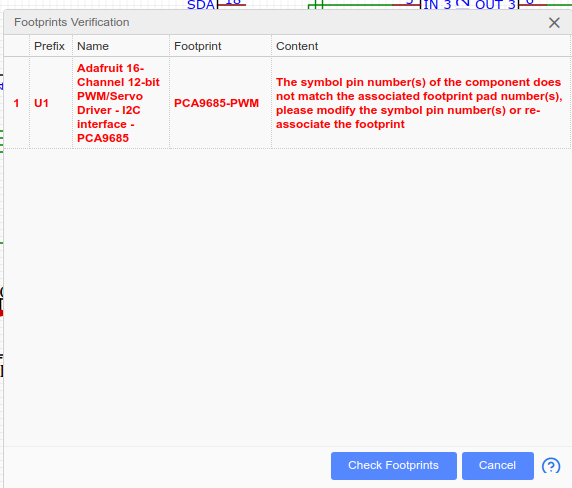
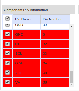
Gotta love these user-supplied components. I'm eternally grateful to the people making these.
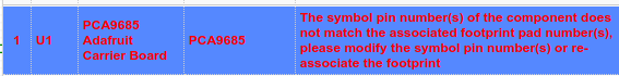
Oh... the problem is just in EasyEDA's imagination anyway. *sighs*
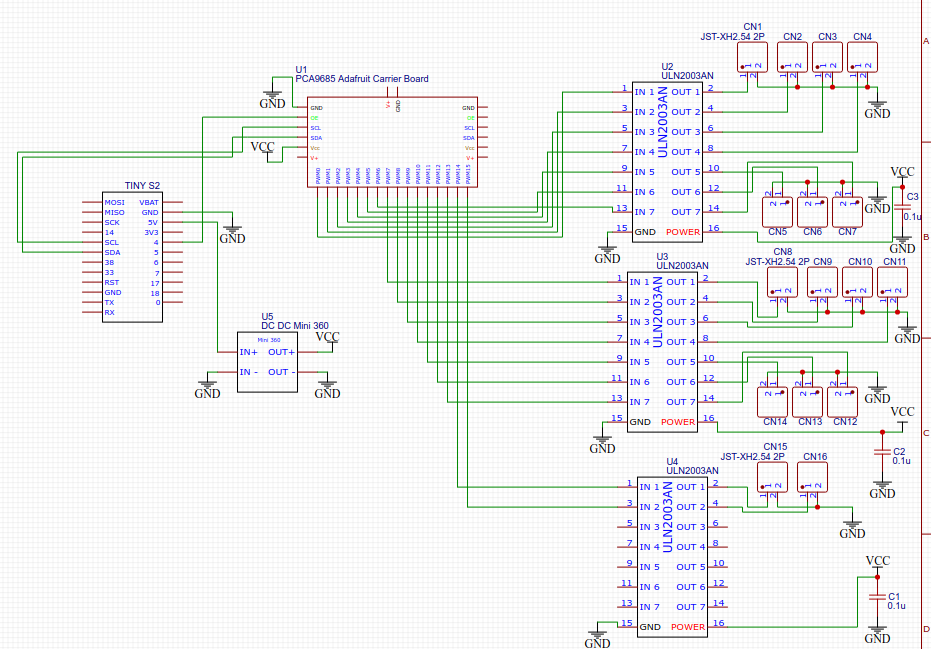
Finally got it after trying a third version of the component design.
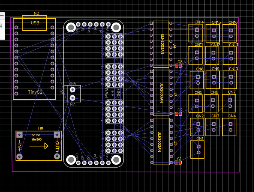
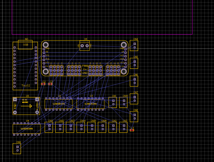
Now let's sort this mess out:
I arranged the headers into a rough grid of threes and put the other component wherever they would fit to form a nice rectangular board with minimal dimensions. I'll give the USB-C power connection a little overhang so it can reach outside the housing.
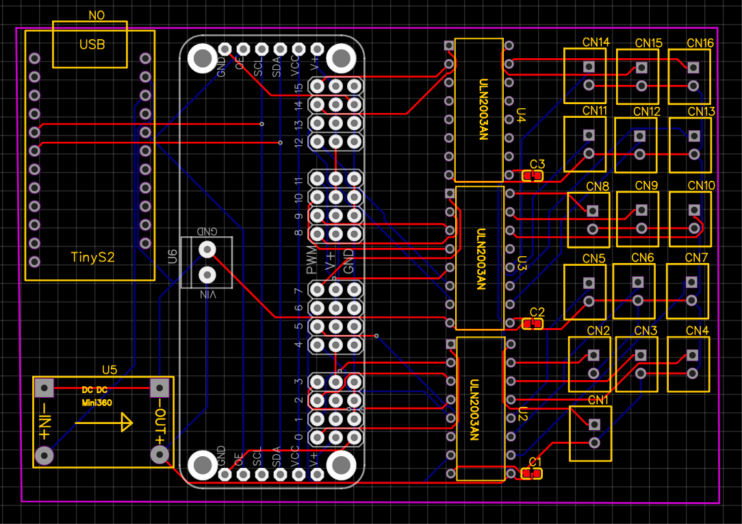
Autorouter, go!
That went better than expected. I forgot this was a dual-layer board. I probably could have even moved them closer together.
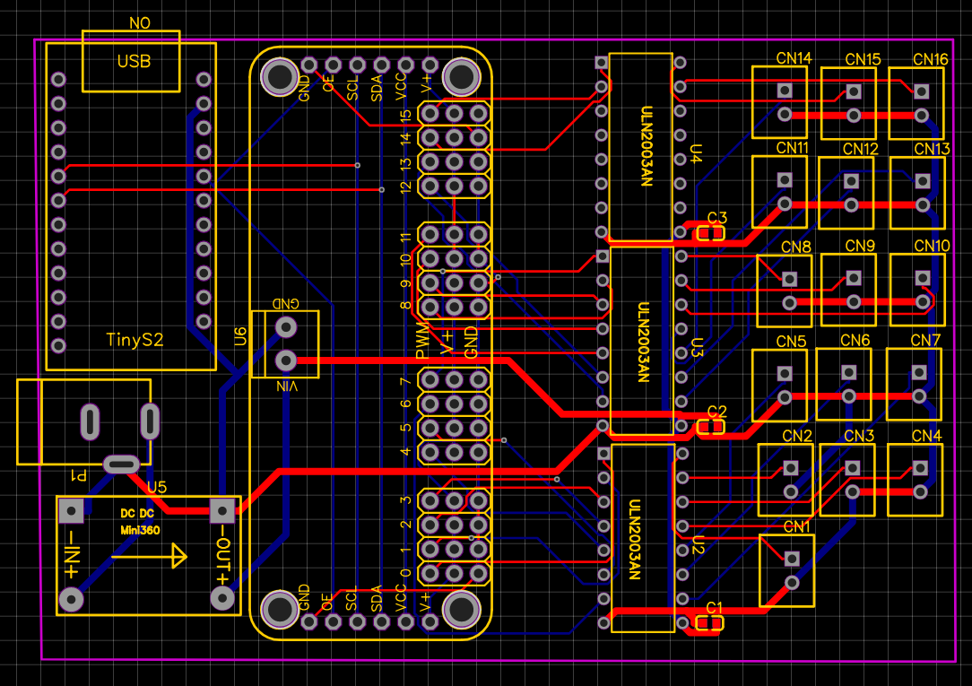
But I should probably increase the track thickness for the tracks carrying high currents.
Given the 1.7 Amps, I'd say 0.75mm should be fine.
Then I'll just wire that to the TinyS2... oh huh.
I've added a barrel jack to power the board instead, I'll just plug in a 12V supply.


 I arranged the headers into a rough grid of threes and put the other component wherever they would fit to form a nice rectangular board with minimal dimensions. I'll give the USB-C power connection a little overhang so it can reach outside the housing.