-
Renault Speech Synthesizer "TYPE 1" 1983 - 1992
07/12/2023 at 20:11 • 0 comments< TO "TYPE 4" | <HOME> | TO "TYPE 2">
"Type1" is used in R11 and R25 from 1983 till 1992
- This type uses Texas Instruments speech synthesis like a Speak & Spell
- The system is fitted in form of a seperate box.
- Languages : French, English, German, Italian, Spanish
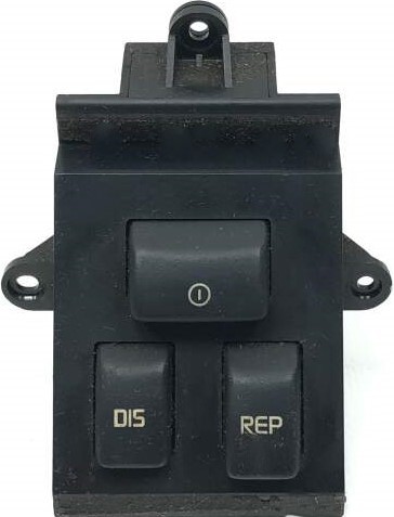
This box went through several very interesting revisions. Each Phase and each Language have own voice ROM´s. On the first versions used in R11 (1983) it talked a lot and spoke detailed informations. The first updated version (1985) of the box was fitted in R25 as "Phase 1". It spoke less detailed informations (probably to get the information to the driver faster). "Phase 2" was introduced at the end of 1988. Phase 2 spoke even less and cut away the TEST function that explained the features in spoken words. TEST was replaced by a simple announcement that all systems are fine (or the faults stored). Phase 2 also got new control buttons.
The boxes are labeled with stickers that can fall off after all the years. That makes it difficult to identify the boxes. You can identify PHASE 2 boxes from its grounding tab on the side of the case wich PHASE 1 does not have. Earlyer versions of PHASE1 used less metal foil around the case. I THINK the earlyest versions of R11 systems used the BARE CIRCUIT BOARDS without a case (wich makes finding them nearly impossible).
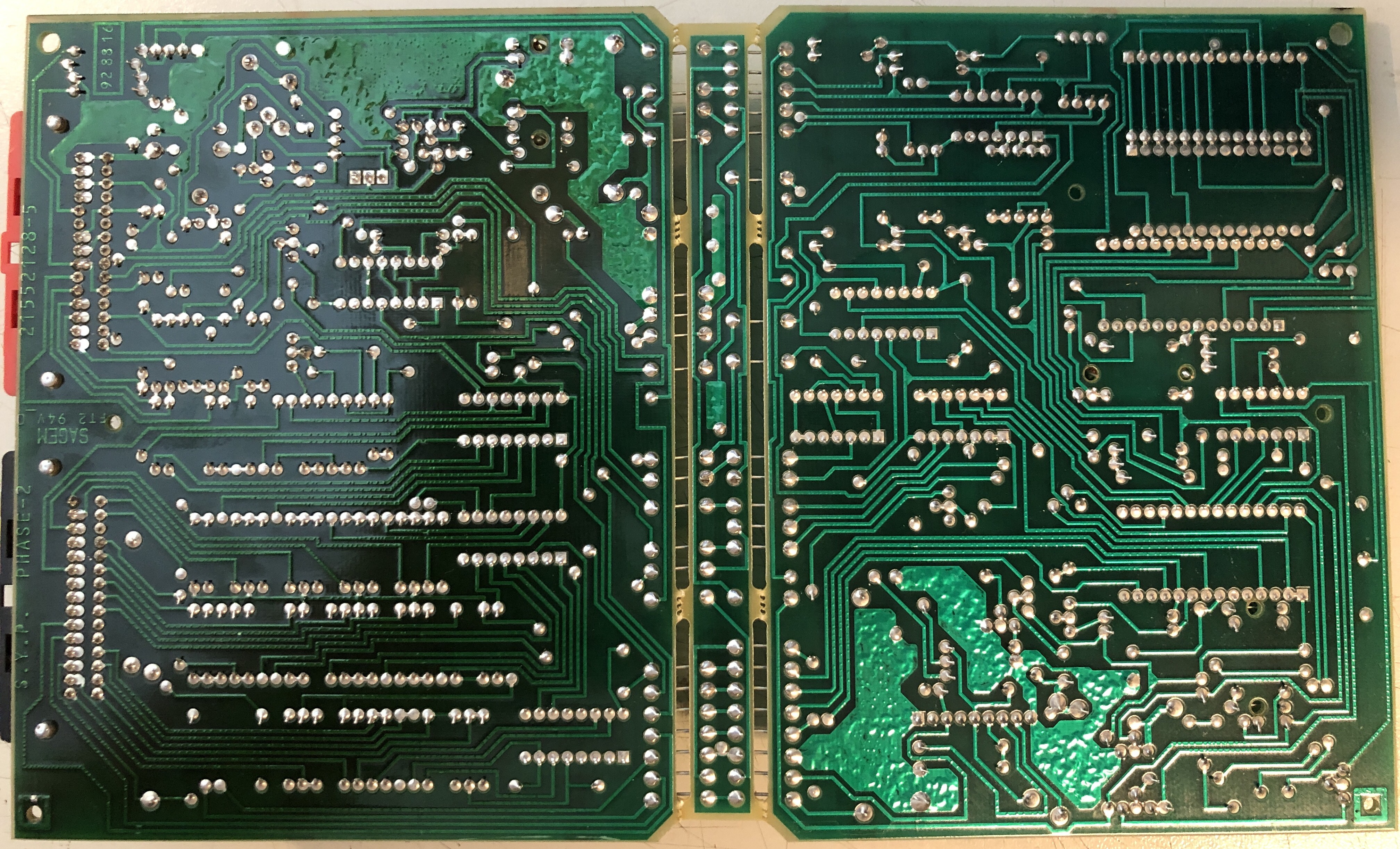
For detailed analysis of the hardware follow this >LINK< to my reverse engineering project.
![]()
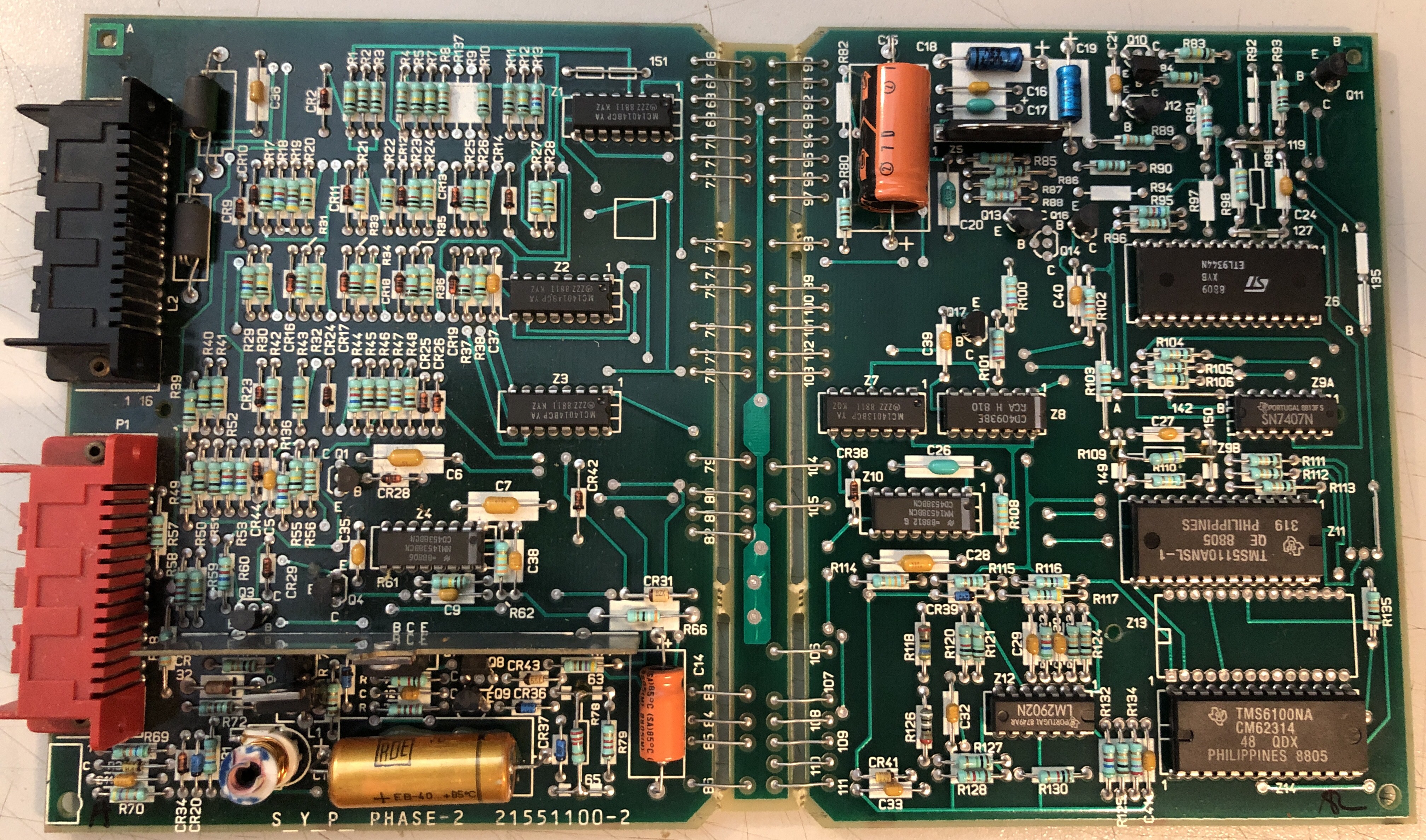
PHASE 2:
The boards shown here are a very early French Phase 2 version. CM62314 is the French Phase2 ROM. TMS5110A above the ROM is the speech synthesizer IC.
![]()
![]()
VIDEOS:
My german Phase 2 version in action:
This is an early version of the box in a R11 (PHASE 0). It talks A LOT!
-
Renault Speech Synthesizer "TYPE 2" 1992 - 2000
07/12/2023 at 16:19 • 0 comments< TO "TYPE 1" | <HOME> | TO "TYPE 3">
"Type 2" is used in Safrane 1 (X54) from 1992 till 2000
- It is a sample based system
- Seperate box (Phase 1 and Phase 2 boxes look the same but have different functions and partnumbers)
(PHASE 1 boxes only contain 1 language and PHASE 2 boxes can be coded to all 5 languages)
ASK ME FOR A DUMP OF THE GERMAN PHASE1 ROM if you want to help finding out how the Audio is encoded on the CHIP!
Controls for both Phases :
![]()
PHASE 1:
SYP x54 (Phase 1) Renault Number Sagem number Language 7700805300 21550991-7 (early REV.) French 7700805300 21552951-7 French 7700805301 English 7700805302 21552953-8 German 7700805303 Italian 7700805304 21552955-9 Spanish (1995) SYP_X54 ALLEMAND (German) SAGEM 21552953-8 / 7700805302 D
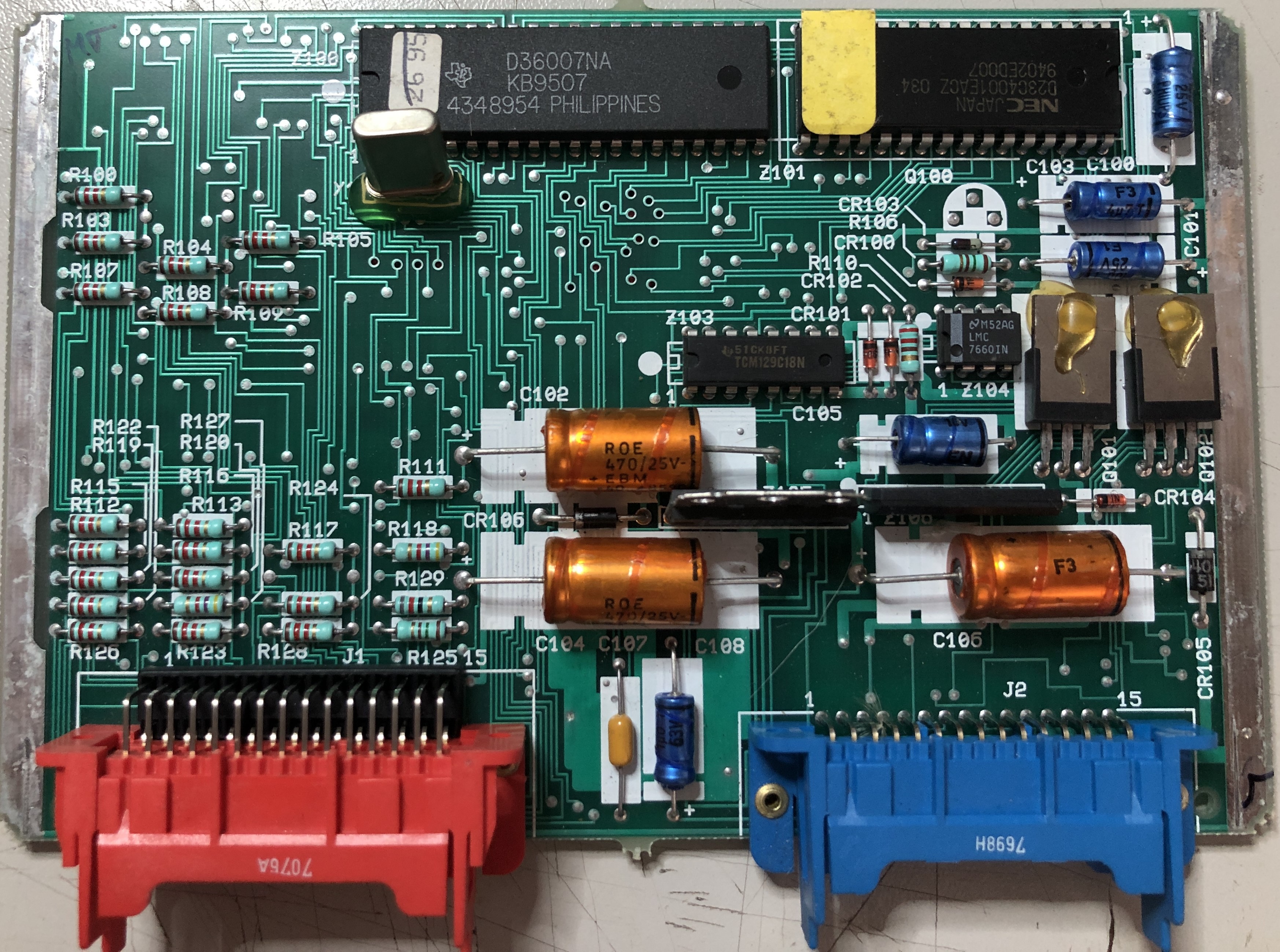
Synthesizer IC (DSP) : Texas Instruments [D36007NA] (probably a TMS320C1X)
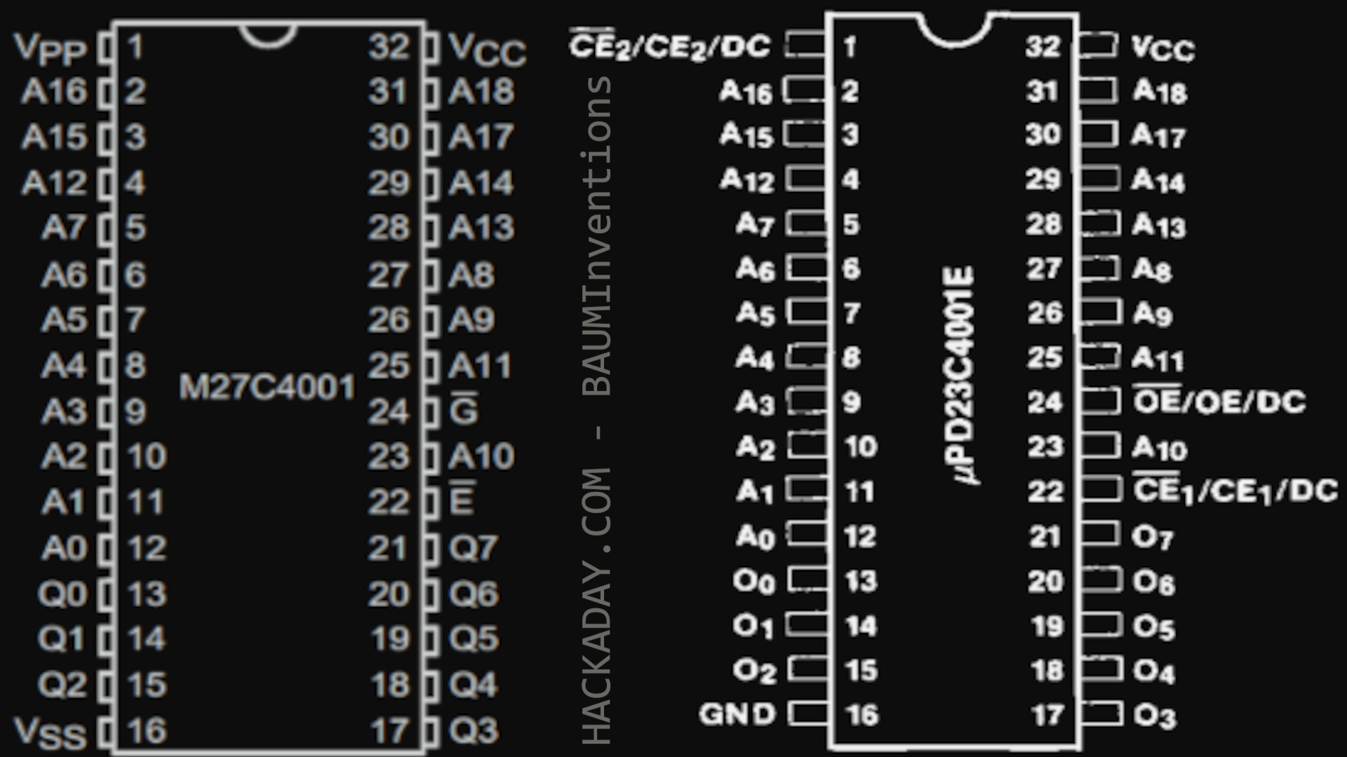
ROM : NEC D23C4001E (DATASHEET)*
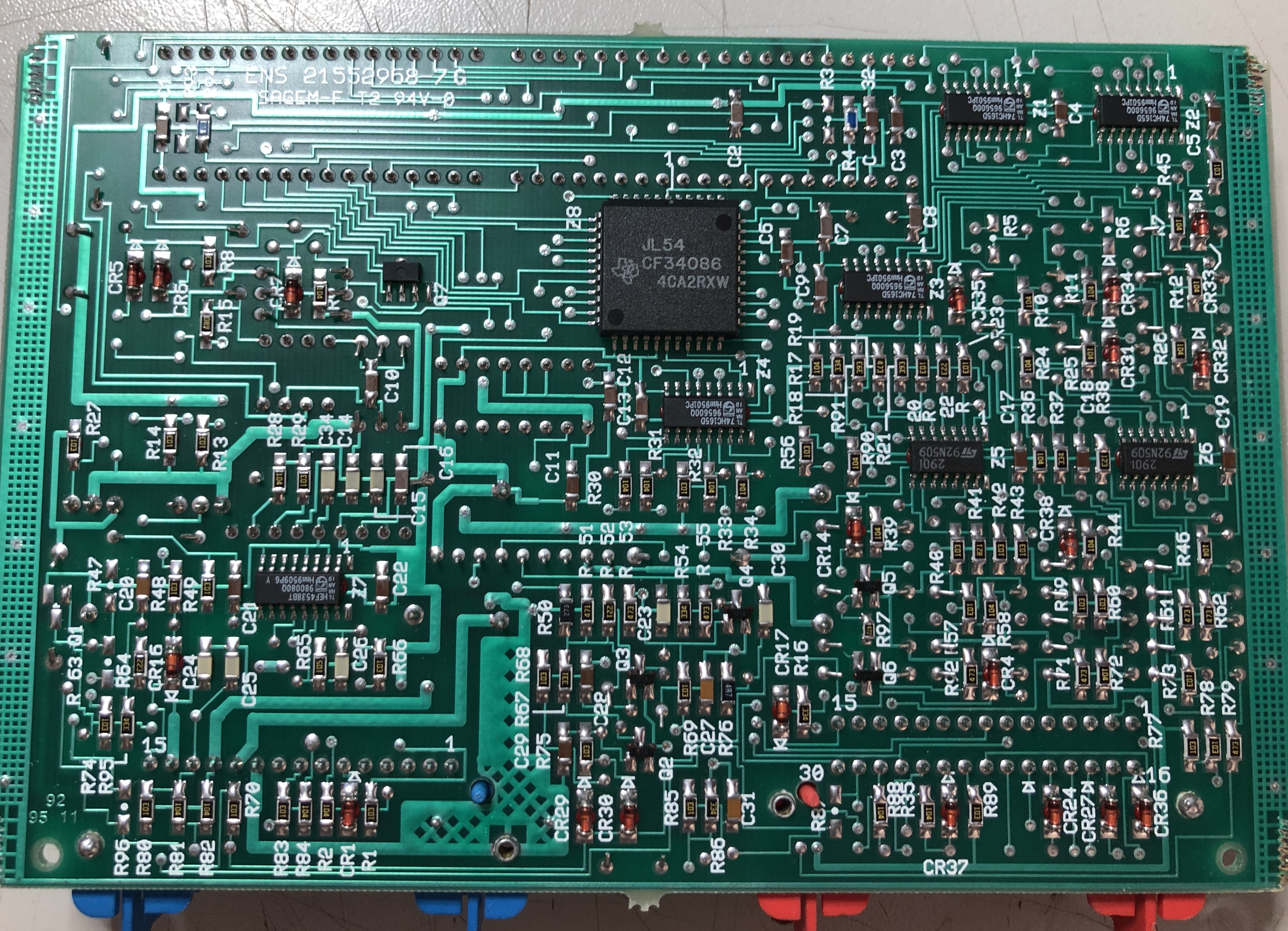
Microcontroller : Texas Instruments JL54 CF34086 (seems UNKNOWN to the Internet!!!)
![]()
![]()
![]()
*The Datasheet shows 3 lines that are "User definable" (active on high or low). On the board CE2 is tied to VSS. OE & CE1 are tied together. My guess is that OE & CE1 are active high... Maybe this info will help me later to read the chip...
Look what i have found... The ROM D23C4001E looks suspiciously like a M27C4001 Rom... Maybe its a simple read with my chip programmer... VPP on the 27C4001 is the 12V programming voltage input. As long as i do not try to write to my ROM it should be safe... The expected input on CE2 of the 23C4001 is +5v during normal operation (as we have seen above from the circuit). If OE and CE1 are configured to work like a normal 27C4001 it should just work to read it...
![]()
Ok. That was too easy. I just desoldered the ROM and put it into my EPROM reader. I used a preset for "NEC UPD27C4001 @ DIP32" and it read just fine... i guess. The Chip is nearly full of data and i have no idea how its encoded. I tried to import it in Audacity with every available setting. I got no results that sounded like a Voice...
Maybe you have an idea? Contact me.
PHASE 2:
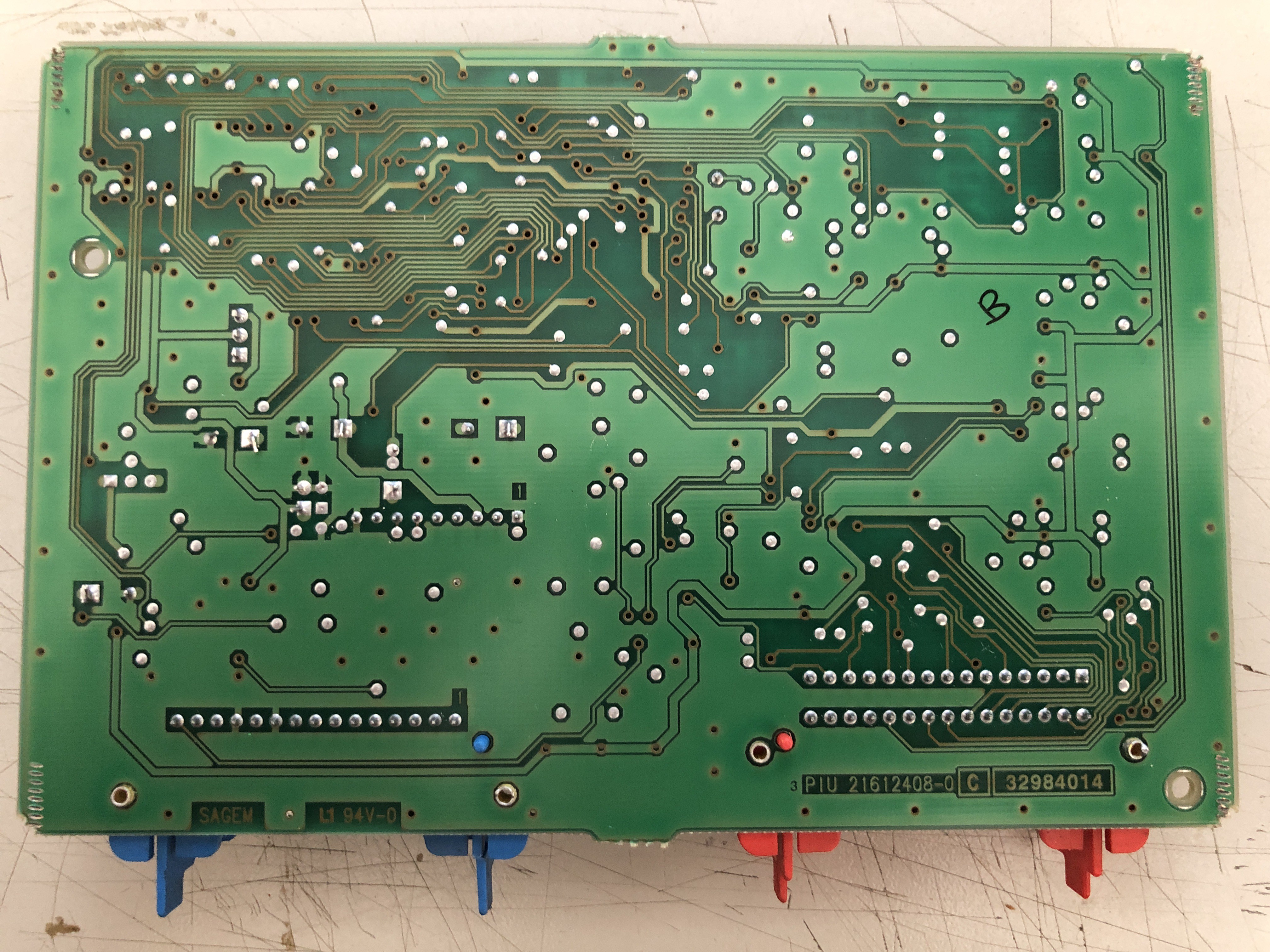
(1999) SYP X54-2 SAGEM 21614185-9/3 / 7700847660
![]()
![]()
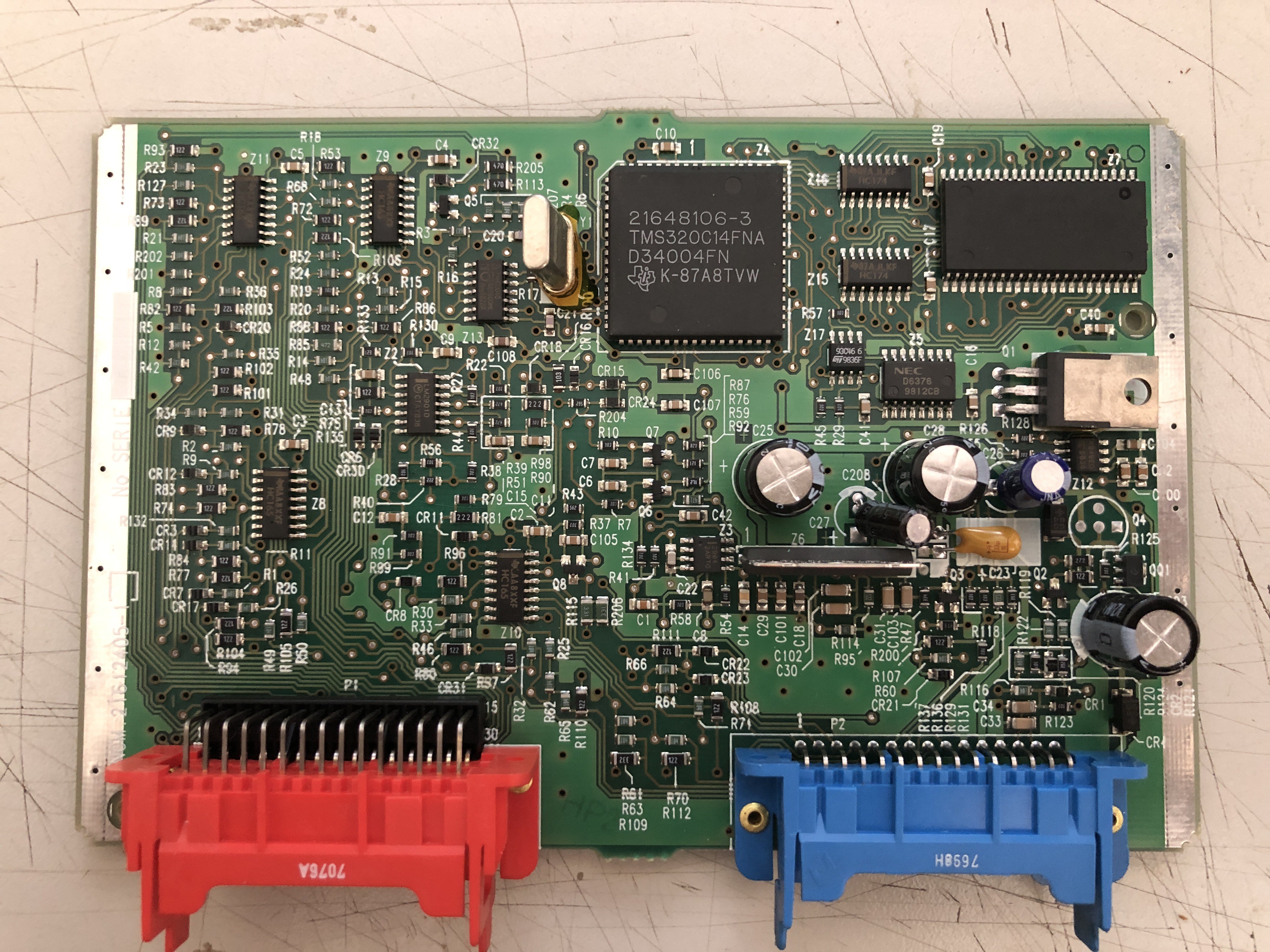
Synthesizer IC (DSP) : Texas Instruments TMS320C14 [D34004FN] (DATASHEET)
ROM : OKI M531602C (DATASHEET)
![]()
![]()
![]()
Its nice that they actually printed the type of DSP on the chip. That gives me a nice clue to what Phase1 is using... The ROM is exactly the same as they used in "TYPE3 (Laguna) Phase 2" (maybe even same content).
Videos:
-
Renault Speech Synthesizer "TYPE 3" 1994 - 2001
07/12/2023 at 14:46 • 0 comments< TO "TYPE 2" | <HOME> | TO "TYPE 4">
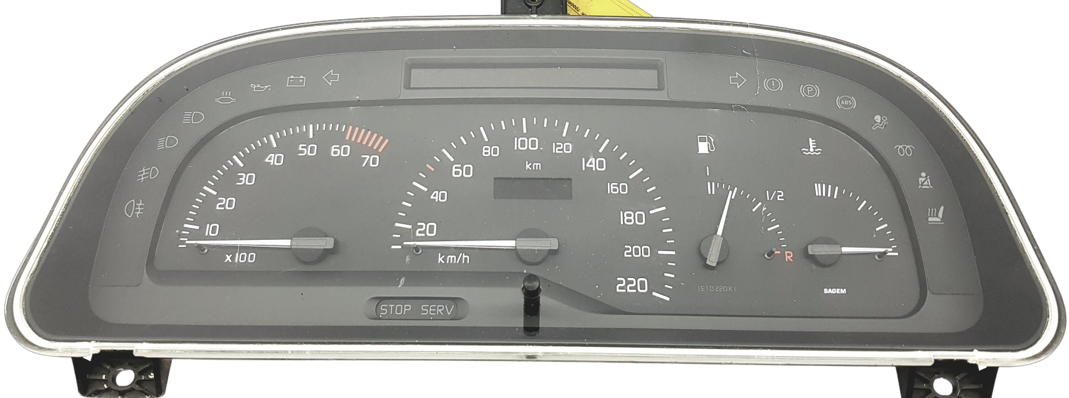
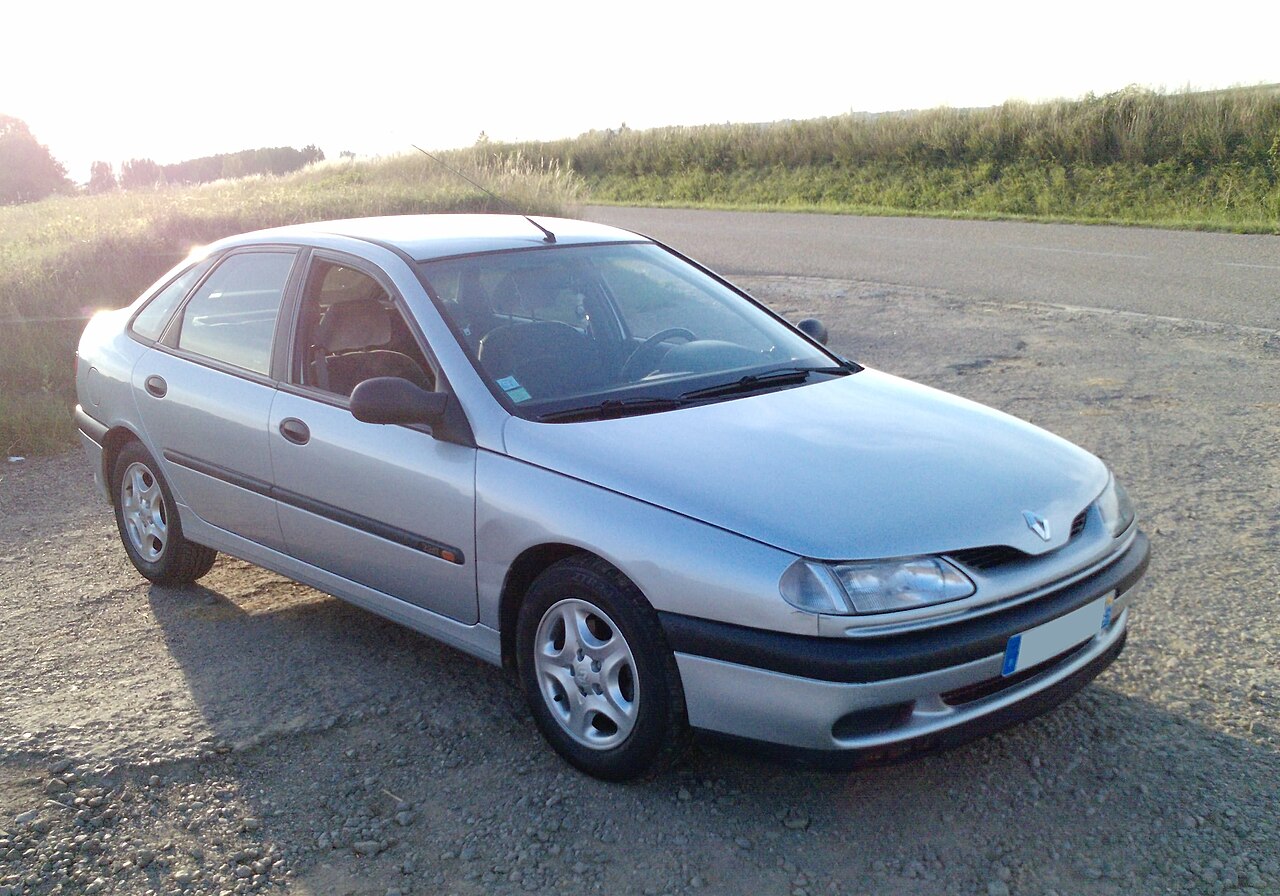
"TYPE 3" is used in Renault Laguna 1 (x56) / 1994-2001
- It is a Sample based system
- The speech synthesizer hardware is integrated into the cluster. (Cluster must have green connector [HIGH version])
- Languages: French, English, German, italian, Spanish, Dutch
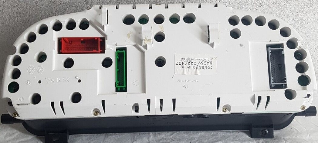
PHASE 1:
![]()
![]()
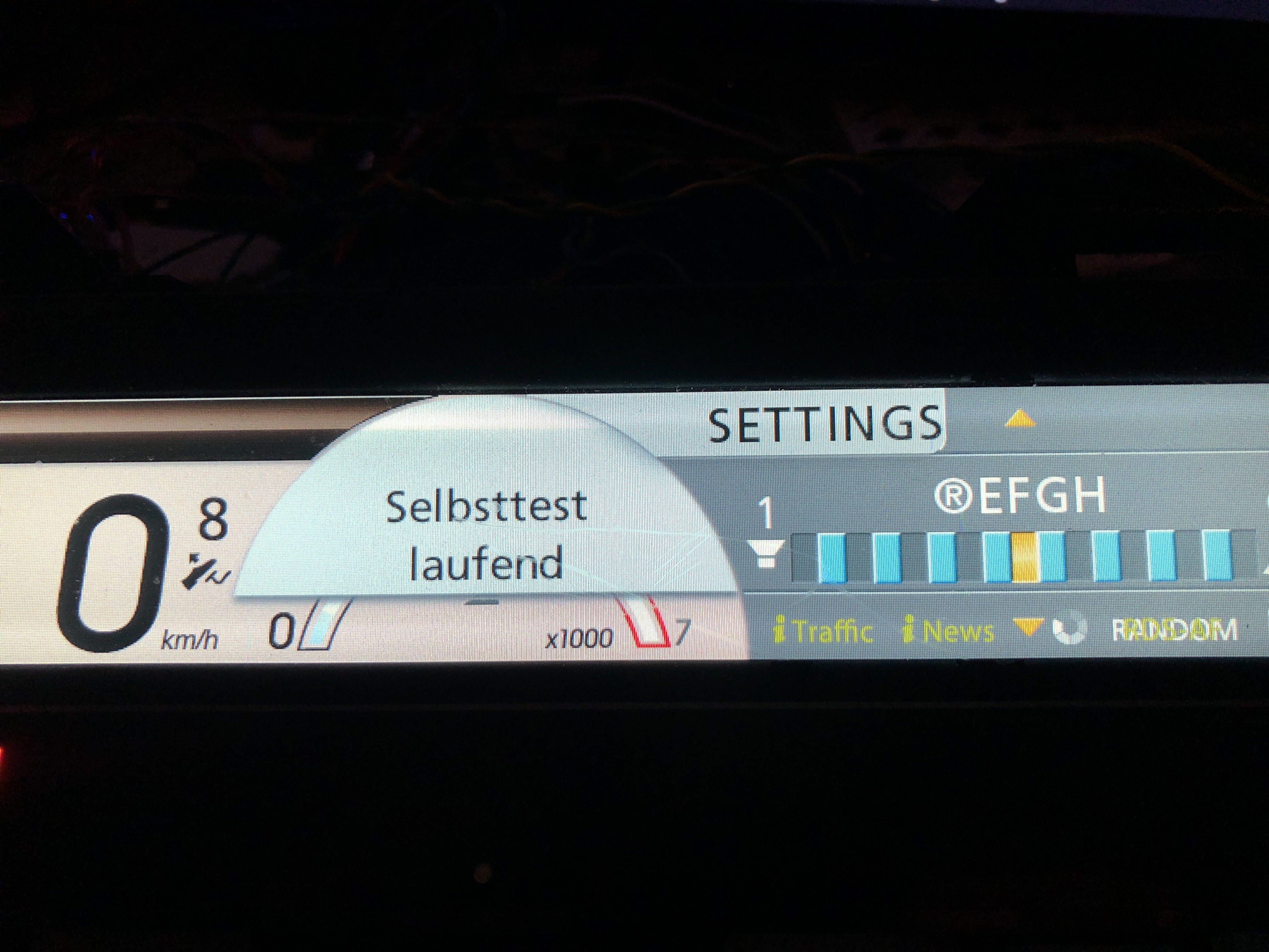
Phase 1 parts have a seperate distance counter display in the center of the cluster. Phase 1 uses a red, a blue and a green connector.
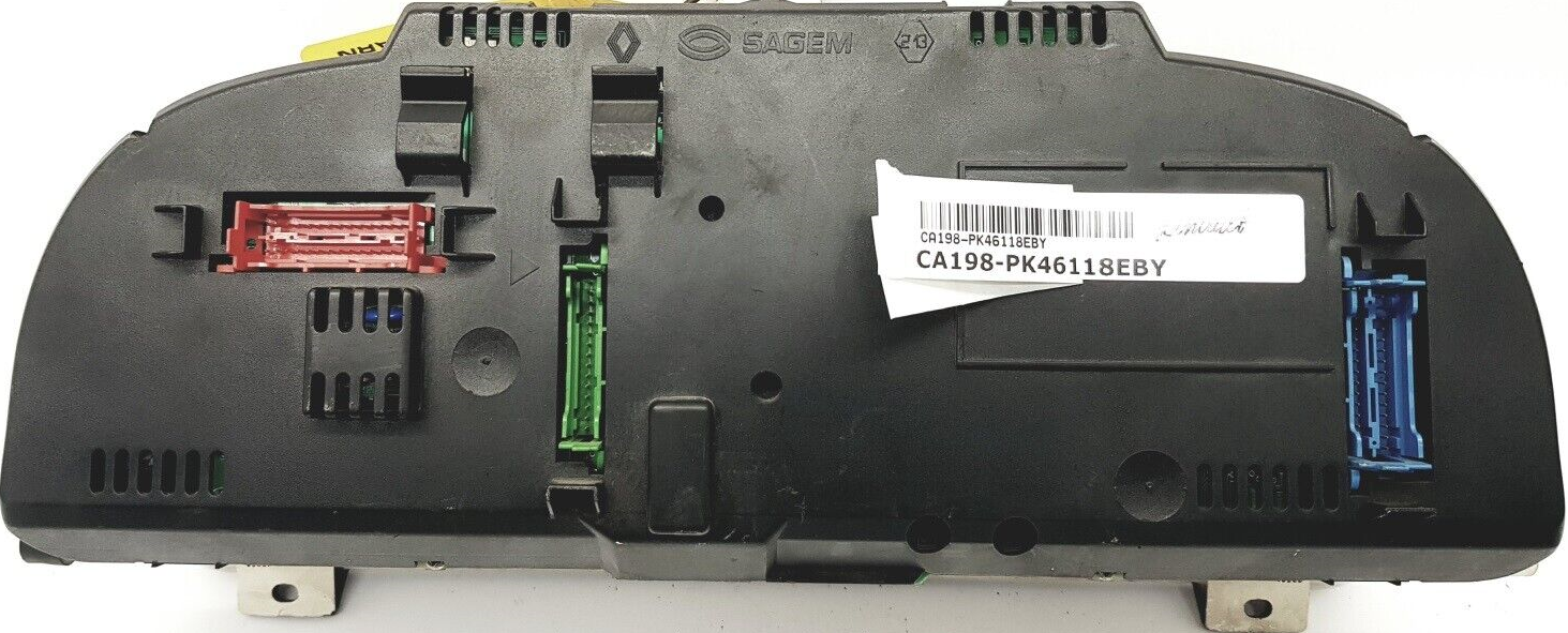
PHASE 2:
![]()
![]()
Phase 2 parts show the distance counter in the upper borardcomputer display. Phase 2 has a red, a grey and a green connector. Phase 2 uses different connectors.
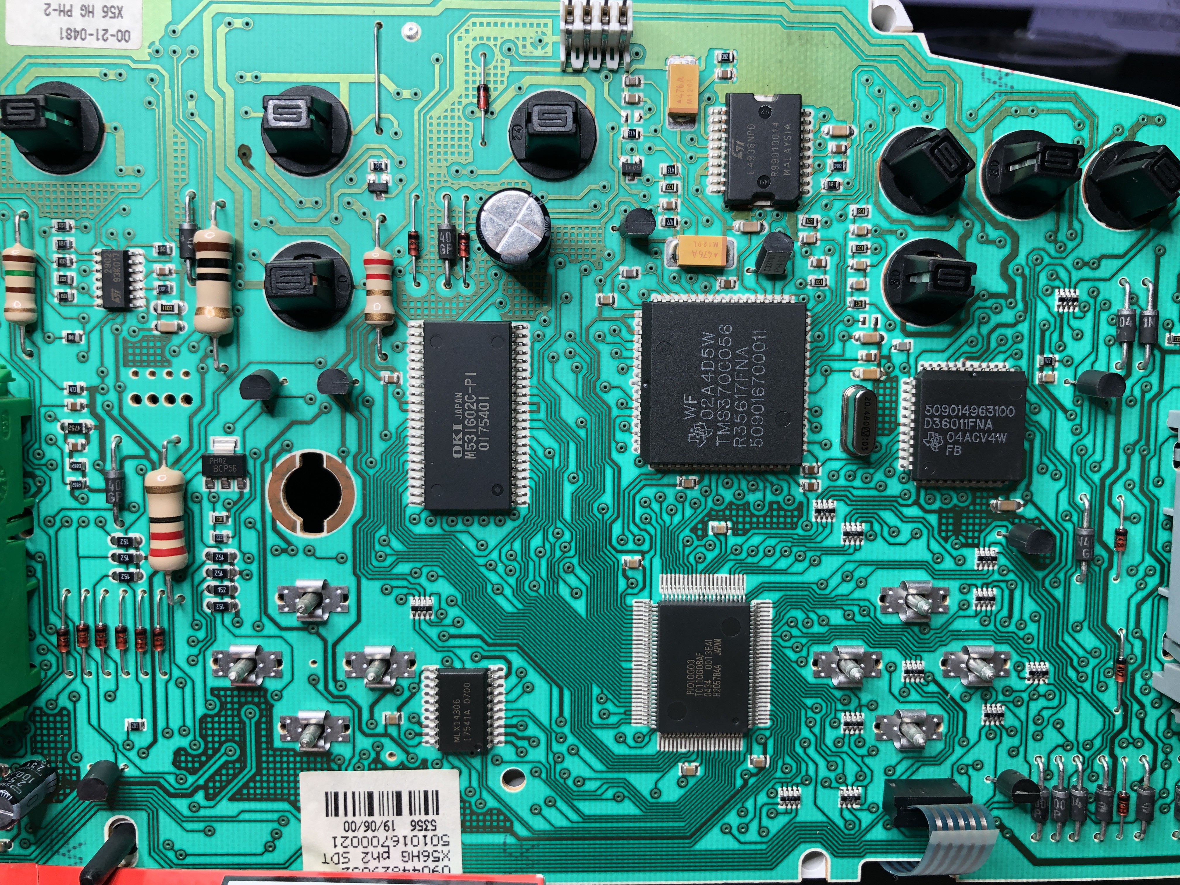
Phase 2 speech synthesizer hardware:
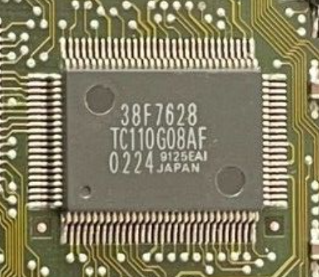
ROM : 44PIN OKI M531602C (DATASHEET) (2MB)
FPGA : PIOLOGO3 (Toshiba) TC110G08AF* (DATASHEET)
MICROCONTROLLER : Texas Instruments TMS370C056 (DATASHEET) and D36011FNA (UNKNOWN)
![]()
* I´m not sure if "PIOLOGO3" is the speech synthesizer... At least it has direct connections to the voice ROM... Maybe it is a FPGA or something like that. If you search for the number below PIOLOGO3 (TC110G08AF) you will find some old Harddisks with this chip... I am pretty sure a Harddisk does not have a speech synthesizer...
![]()
EDIT: I was right... it is a gate array. TC... sounded a lot like a partnumber from Toshiba. some searches later i found the Toshiba TC110G gate array in the version 08 (TC110G08) with around 3200 usable gates. >DATASHEET<... I have to make some measurements to see wich of the IC´s generates the Voice output that is fed into the amp...
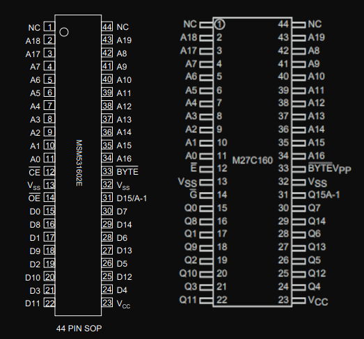
I finally found a ROM Chip that looks exactly like our MASKROM ... I think its time to order a adapter so that i can try to dump it... M27C160 (DATASHEET) seems to be the regular version of the MSM531602E
![]()
Videos:
Changing language with tester on PHASE 2:
Voice example Phase 1 english:
-
Renault Speech Synthesizer "TYPE 4" 2001 - 2005
07/12/2023 at 02:33 • 0 comments< TO "TYPE 3" | <HOME> | TO "TYPE 1">
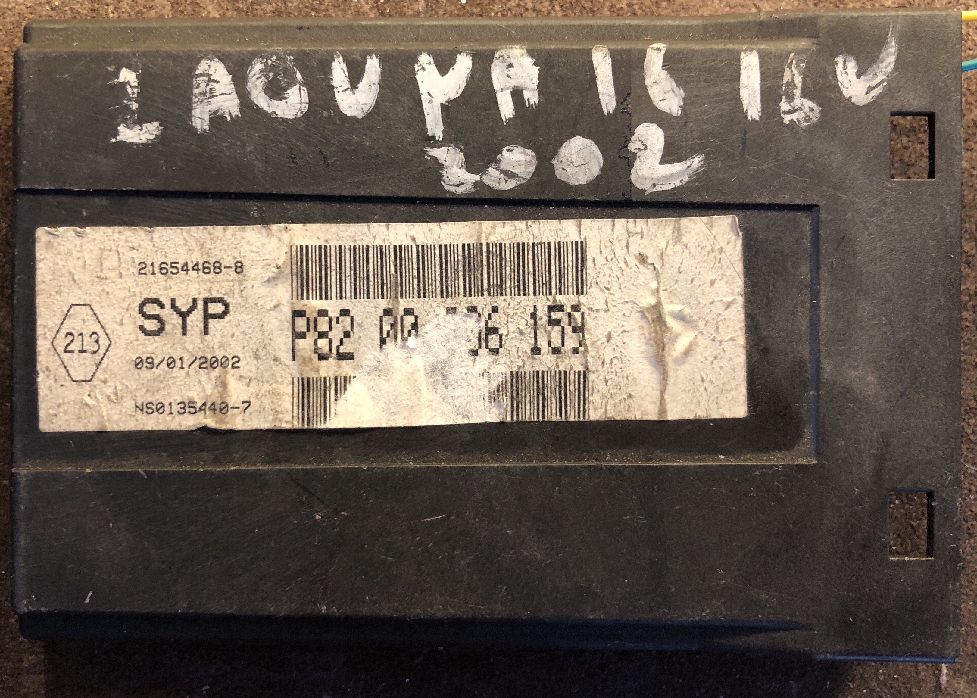
"Type 4" is used in Laguna 2 / VEL SATIS from 2001 till 2005 (after facelift in 2005 speech was not available anymore)
- It is a sample based system.
- Seperate Box (Uses CAN BUS communication) [contains all languages]
- Languages: French, English, Italian, German, Spanish, Dutch, Portuguese, Turkish, (Japanese, Russian)
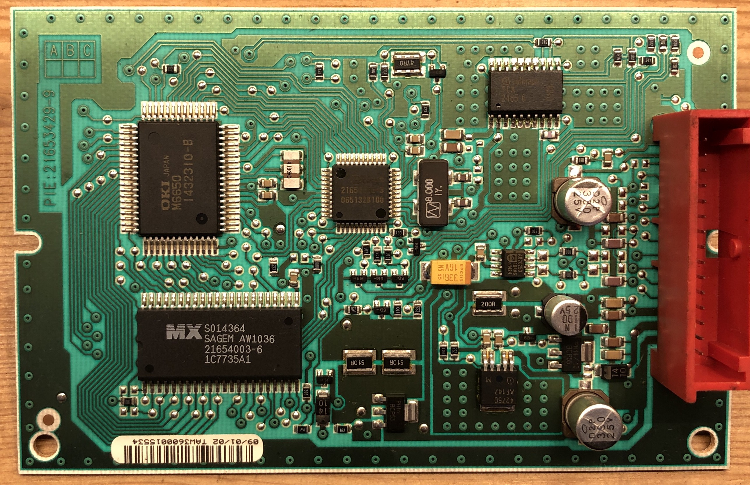
P8200006159 / 21654468-8 | January 2002
Voice Synthesizer IC : OKI M6650 (Datasheet)
ROM : UNKNOWN 44Pin Macronix (MX) ... [branded as SAGEM AW1036]
![]()
![]()
![]()
A lot of useful informations HERE
For this system to work you need the "high" version of the cluster (the one with the LCD display). This version of the cluster has the second CAN BUS connector to connect the speech box to. The speech is triggered by several control units over CAN-BUS not just the informations from the cluster like in LAGUNA 1.
-
Types of Speech Synthesizers (SYP) used by Renault
07/08/2023 at 01:20 • 0 comments"Boitier de synthèse de la parole" (short form "SYP") is the name for Renault´s speech synthesizers they used from around 1983 till 2005.
In these 22 Years the system evolved from a fully synthesized speech output with complex interconnected circuit boards into digitized speech output from basically 2 chips on a mobile phone sized circuit borad.
The systems were available on better equipped cars of their upper class models. I have categorised the systems into 4 "Types". To learn more about each system just follow the ">READ MORE<" links.
------------------------------------------------------------------------------------------------------------------------------------------------------
Type1: 1983-1992
![]()
------------------------------------------------------------------------------------------------------------------------------------------------------
Type2: 1992-2001
![]()
------------------------------------------------------------------------------------------------------------------------------------------------------
Type3: 1994-2001
![]()
------------------------------------------------------------------------------------------------------------------------------------------------------
Type4 : 2001 - 2005
![]()
-
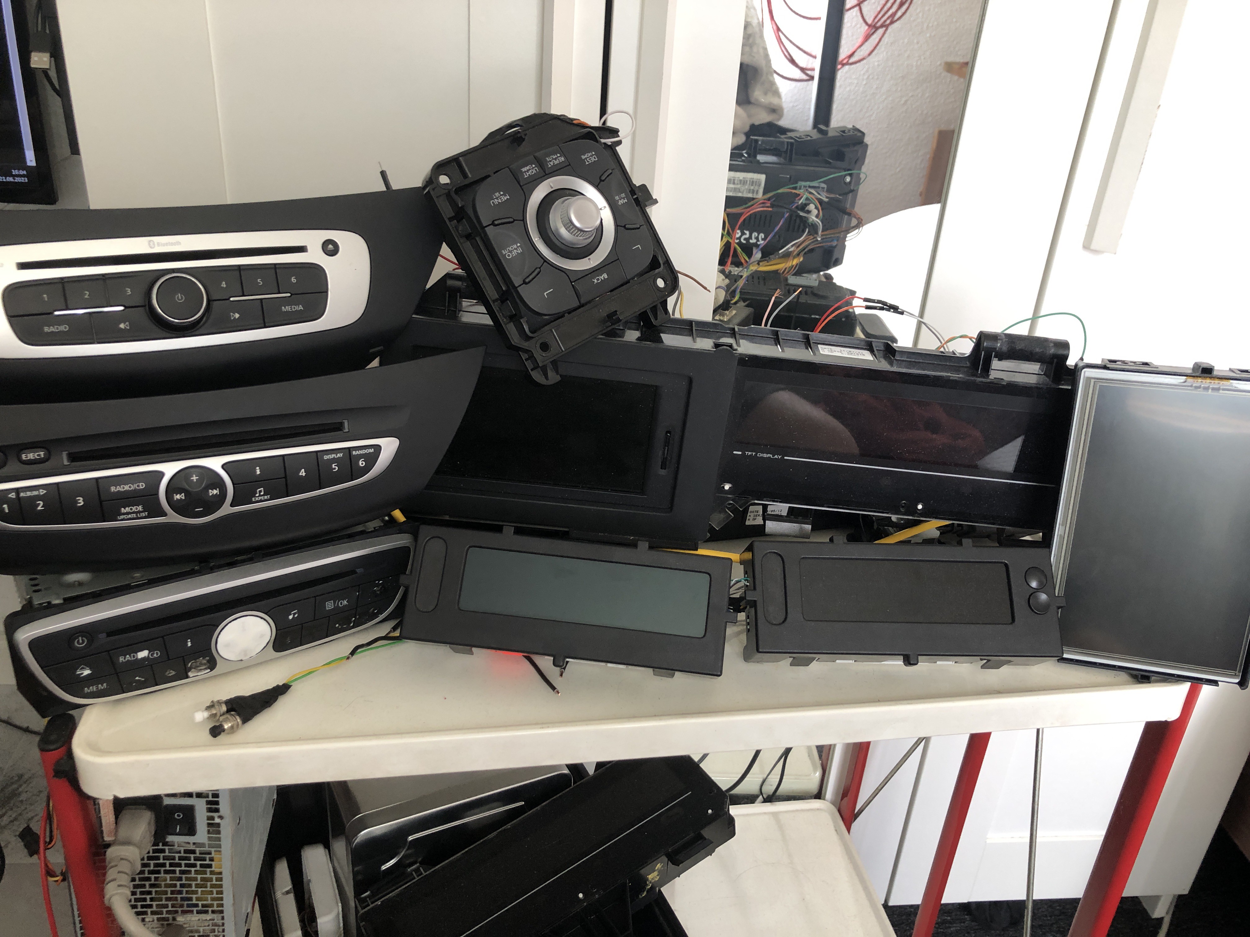
Types of Renault Radios / Displays / Protocols
06/21/2023 at 14:36 • 0 commentsMy goal is to create a useful guide for all Infotainment systems Renault has used over the years that use some kind of data communication between components.
![]()
Components that i own will be reverse engineered and documented. If you have any new informations that need to be added please feel free to leave a comment and i will see how we can do that.
To be fair all this is pretty complicated and i will do my best to give it some kind of structure... Links will bring you to more information i have written.
This Page will evolve over time. Its not the final form yet!
Lets get a small overview of general systems they used:
- Radio + Display
- Radio with integrated Navigation system + Display (earlyer models)
- Radio + Display with integrated Navigation system (later models)
At this point in time i know that external Amplifiers, CD Changers and maybe external Navigation computers that use data communication exist in Renaults universe but my main priority is the communication to the Displays and the protocols they used. I can not gurantee to cover each and every component they ever used.... but i will try ;)
Small rant on complexity:
Lets first talk a little bit about the weirdness that comes with making tech for cars. A specific car model normally is made for a long period of time. Even if the chassis of a car is sellable in 10 years the tech inside often is not. So traditional car manufacturers invented Facelifts / Phases . This is a point in time where new Tech or Parts are introduced into an existing model together with some fresh looking new outside parts. Now there is a weird combination... A new Model of car is introduced with new tech, and all other cars will get the tech but without a Facelift on the outside. Ok, thats a Facelift too... but just a technical Facelift. This will result in car models that have several different generations of Central electronics, Engines, Infotainment, and exterieur Parts all mixed in the wildest combinations over the years. At Renault there was a point in time where the oldish base cars could not natively talk to all the new tech they have thrown at them so they needed a "translator". A so called Multimedia Interface Unit wich was a can bus transceiver that rewrote all the can messages to make all of that compatible.
Sometimes i have the feeling that some decisions in the car tech sector are made to keep jobs relevant. Not that this is a bad thing to keep Jobs, but it adds to the uneccesary complexity to the systems used in cars that we all pay for (if we drive cars). Of course it is better to have more seperate parts in case something breaks. BUT just take the money you saved on the complexity and put it towards better quality in the one part... Ok enough of my foolish rant.
What i wanted to say was :
Sometimes you can find several versions of Radios and Displays in one car model that are not compatible to each other.
My idea was to take each car and list the Radios / Displays they used for it. But after i found out nealry all cars went through several different general systems that used different Radios / Displays and sometimes different remote controls i decided to not sort by car but instead sort by system. I had to come up with names for the systems. If i can find names used by Renault in its documentation or on the Parts i will use those.
Radio + Display (with integrated Navigation System)
2008 - 2016
This Generation consists of 2 different Radios, R1 and R2. R1 is a basic CD Player and AM/FM Radio. R2 is a little bit better equipped with Bluetooth
Display A2 and A3 are also the MIU! If Display A2 or Display A3 are replaced by TomTom a MIU is mounted (except for Scenic 3 where the Cluster is the MIU).
Radio R1 + Display A2 (Protocol R1):
![]()
Radio R1 + TomTom (Protocol R1):
![]()
Radio R2 + Display A3 (Protocol R2):
![]()
Radio R2 + TomTom (Protocol R2):
![]()
In 2011 TomTom Display got an update and now has 4 antenna...
Read more -
Renault "radio R1" Display protocol reverse engineering (Content)
06/10/2023 at 22:41 • 0 commentsAfter we understood the protocol it is time to have a look at the content of a display message.
![]()
You should be familiar with Hexadecimal to properly follow this Blog.
To not make it more confusing as it is i will skip telling you about "endianness" and just say:
We use the way the Arduino IDE counts the Bits and Bytes.
- Bytes in a message are counted from 0 to 7 from "left to right".
- Bits are counted from 0 to 7 from "right to left".
ATTENTION:
There are slight differences wich parts of the Message are used depending on our output device. The small LCD Display , the Scenic cluster and the TomTom Navigation generally will display the same but use more or less Bits and Bytes to do so. I will try to make the differences as clear as possible.
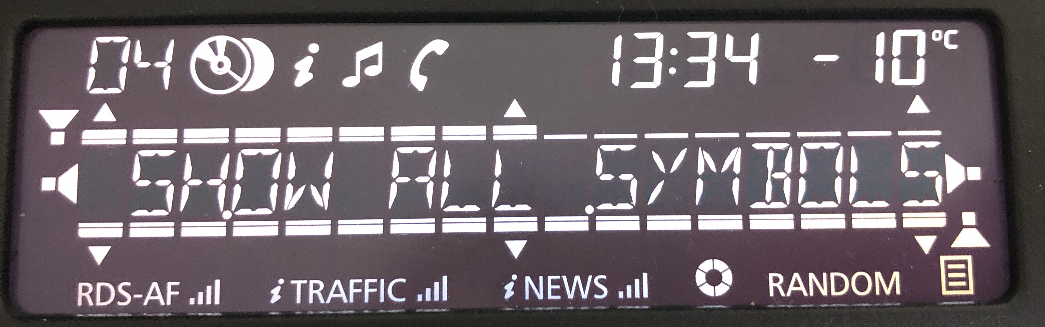
![]()
The LCD Display uses 4 Bars, 6 Arrows, 4 Speakers and Text to create some kind of a menu structure. All of these symbols and bars can be set individually. The LCD Display can show any symbols or bars at any time. We just have to set the specific bit for a symbol or bar and it will show up. This will give you a wide range of flexability on how to show menus. Thin and thick bars above and Below the Text will indicate "boxes" and "highlights" OR they will be used as bars (fader, balance, Bass Treble ...)
Scenic cluster and TomTom Navigation do not have the limitation of a segmented LCD display and can show a nicer menu structure wich is more specific to the content. Scenic cluster and TomTom use Byte1 in Consecutive frame 9 as a "message Type". Byte1 can be 0x00 (0) - 0x1D (29). Here we have 30 different pages to show all possible menus the radio is abled to generate. Another difference is that the "bars" "speakers" and "arrows" used for the LCD display are not shown here. But some parts of these elements are used to control the elements on the pages. Also not all Symbols will show up on all pages. The last bigger difference is the "modifier". On the LCD display the "modifier" will just show "cd" or "cd changer" symbol. On Scenic cluster and TomTom the "modifier" works different. In addition to "cd" and "cd changer" we also have a "fm" and "aux" modifier. This modifier will change some of the pages. On a couple of pages we get different Texts.
Scenic cluster an TomTom have a "big" and "small" display mode. We can define if the message will show up as a full page or just as a status bar. This is not used on the LCD Display.
The last slight difference is between Scenic cluster and TomTom Navigation... Scenic cluster is a little bit tighter in its restrictions. TomTom will show more of the Text on nearly all of the pages. Also Scenic cluster has many fixed names displayed on each page .
But i will point out all differences and provide examples for every case in the upcoming Project.
Ok, let´s go:
The fixed stuff that never changes:
- In general Byte0 in all messages of this "block" contain an "identifier".
0x10 to show this is a split up "block" with more then 1 message.
0x21 - 0x29 are the numbering of each following message of this "block".
This is "ISO-TP" and we replicate these Bytes for our messages.
- Byte 1 in the First Frame (line 2) tells us the length of the complete "block"
0x3F converted from HEX to Decimal is 63.
63 Bytes will follow AFTER the length EXCLUDING the "identifiers" !
Data : First Frame : Byte 2 - 7 (6) / Consecutive frame 1 - 8 : Byte 1 - 7 (56) / Consecutive frame 9 : Byte 1 (1)
6 + 56 + 1 = 63 ... The length is fixed and we replicate it.
- Byte 2 in the First Frame is always 0x40. And Bytes 2 - 7 in Consecutive frame 9 are always 0x81 filler Bytes.
Thats it for the fixed stuff ... Lets start with the interesting part:
Bytes that are changing:
Visability control:
Byte 3 4 and 5 in the first frame control if and how the message is shown. Bytes 3 and 4 enable or disable if the Message / Text is shown. If Bit0 in Byte3 and Bit4 in Byte4 are 1 the Text set in...
Read more -
Renault "radio R1" Display protocol reverse engineering (Protocol)
06/10/2023 at 04:08 • 0 commentsAfter we have a working Test Setup and properly working tools its time to start digging into bits and bytes.
I started looking at just the Multimedia can bus of the Scenic 3 Cluster without any other connected devices.
![]()
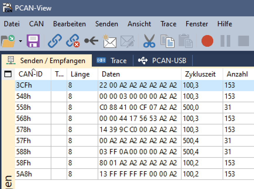
There is a LOT going on. even without any connected devices. This is why its important your tools are FAST.
This is our baseline. We really know everything we see here is not from the Radio.
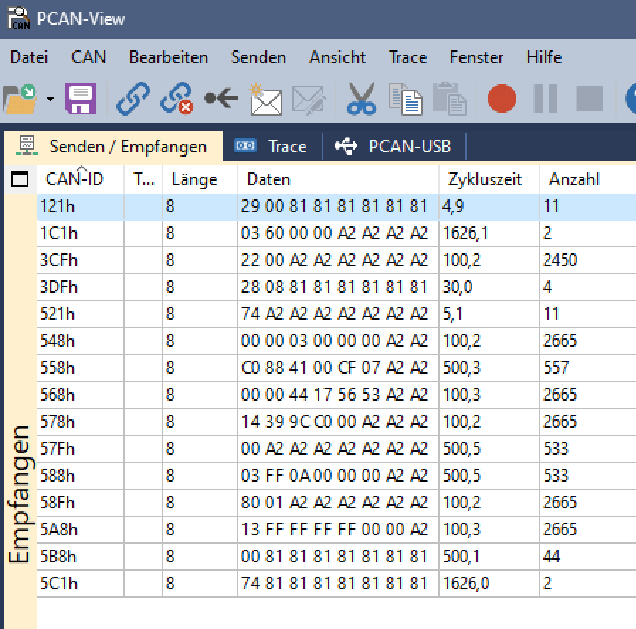
You can see a lot of those "A2" Bytes. These are filler Bytes. Now we know the cluster uses A2 fillers to make all messages 8 Byte long.
The bytes are all static in all 9 Messages. Nothing is changing. No obvious signs of anything trying to connect to anything.
The next step was to connect the radio to the cluster and see if something changes.
![]()
Oh yes. Things have happened. Awesome.
We have new 81 Filler bytes. These come from the Radio. Now we have 15 Messages. 4 Messages have 81 filler Bytes ... wait a minute... 15 minus 4 isnt 9 (we had before) its 11 ...
So we got 2 new ID´s coming from the Cluster....
Also noteworthy only one of the new messages from the radio is sent periodically. The other 3 new messages from radio and the 2 from cluster only appear when something changes on the display or the radio and the display are connected together.
Thats calling for a "trace". A trace is a recording of the can network. You can see all the messages that were sent in the time you recorded the trace.
Because the messages are spread around pretty much the entire range of IDs a Filter is not useful. At least for now...
Pcan-View can export traces and Open Office Calc an open these traces as a some kind of usable Spreadsheet.
After i removed all the IDs with messages that have not changed when i connected the radio i was left with just the communication between Cluster and Radio...
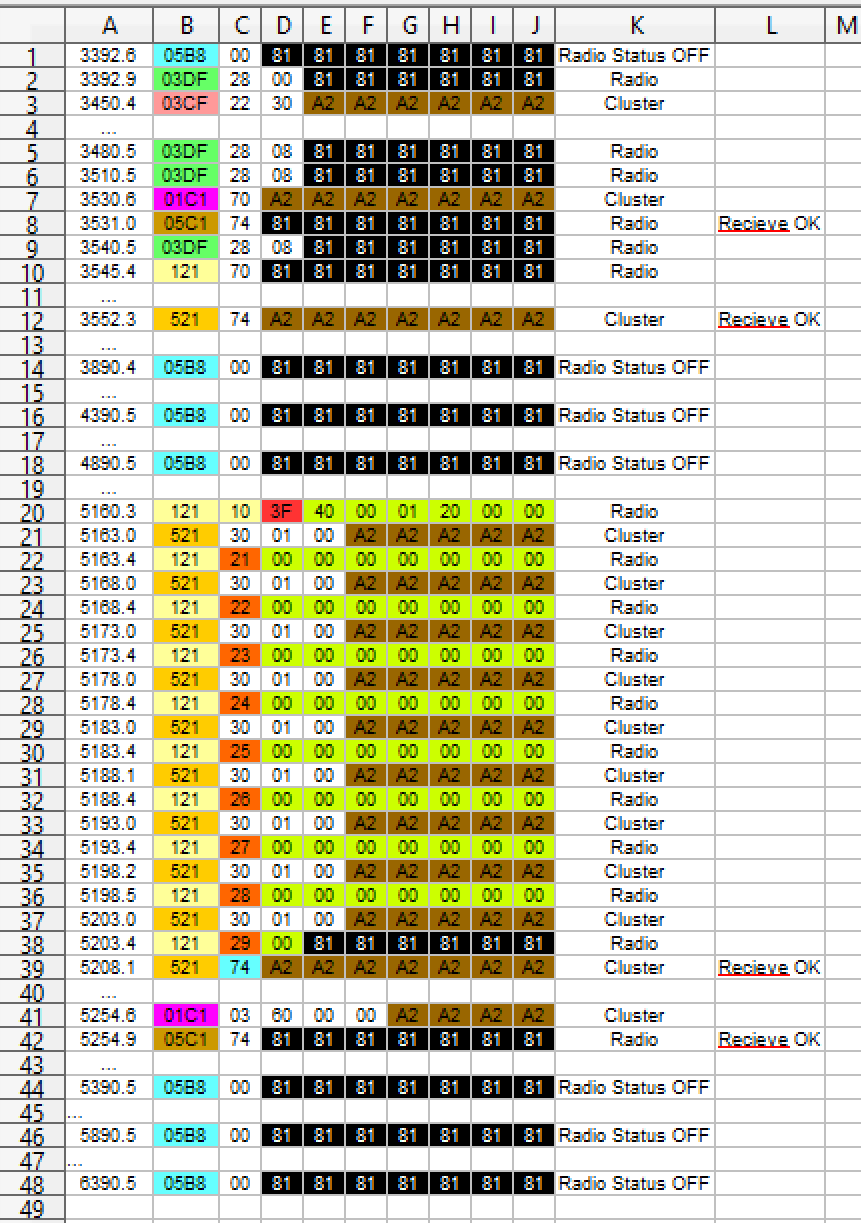
Some more cleaning and colouring later and i had a pretty understandable representation of what is happening.
![]()
Lets explore whats happening in short form first.
Handshake:
- In the first Row i connected the Radio. The Radio starts to send 0x00 at ID 5B8.
- Also the Radio starts to send 0x28 0x00 at ID 3DF.
- When this happens the cluster stops sending ID 3CF.
- After that the Radio changes the content of ID 3DF to 0x28 0x08
- The cluster sends a 0x70 at ID 1C1.
- Radio sends a 0x74 at ID 5C1
- The Radio sends a last time ID 3DF and stops using it.
- Radio sends a 0x70 at ID 121
- Cluster answers with a 0x74 at ID 521.
Ok thats a lot to take in before we even saw anything that looked like Display data. Lets see whats has happened here in a little bit more detail.
ID 5B8 is used by the Radio to tell its general state. It just used to tell us if the Radio is off (0x00) or on (0x10). It also turns to 0x11 for a short time if a Button on the radio was pressed.
The first message we saw from 3DF was 0x28 0x00. Thats the Radio telling us it is available for a connection to a display.
3CF is the same as 3DF but from the cluster side. That it went away after the Radio started using 0x28 0x08 on 3DF is the cluster telling us it has seen that the radio has seen the display :D.
This is why 3DF also goes away. 3CF and 3DF are just used to tell each other that there is somebody to connect to.
The following 0x70 on ID 1C1 is the cluster asking the Radio if it is possible to establish a connection to 5C1 (notice +400 in the ID).
The Radio answers with a 0x74 on ID 5C1. Thats the OK to the Cluster for a connection from 1C1 to 5C1.
At this point we have started the Handshake and 3DF stops sending. The Radio and the cluster are sure there is somebody to properly talk to.
Now the Radio also sends a 0x70 on ID 121 (question to ID 521 for a connection) [notice again +400 ID]
The cluster promptly says "I saw your question and everything is ok" by sending 0x74 on ID 521.
And thats the whole Handshake of the protocol. Some hellos. A little bit of...
Read more -
Wich tools do i use to play with CAN BUS ... and why...
06/09/2023 at 21:02 • 0 commentsThis is just a little writeup i can link to if i need to explain the tools for any CAN BUS Project i work on.
I am pretty sure the tools i use are not the best, cheapest, most expensive, well known or anything else ... They are just the things that have worked best for me over the years.
Back in 2012 when i started playing with CAN-BUS the choice of reasonable priced tools available to me was quite thin... Also my knowledge was quite thin too :) ...
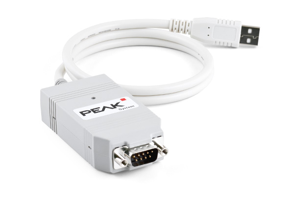
I was not sure if i do things right. A lot of experiments with Can Shields and random Car hardware from the Scrapyard (and my car) led to non satisfying results in even reading can bus. I didnt know about Baudrates, or termination resistors... For the beginning i just wanted a out of the box experience that already does the things i want. I just wanted 1 layer less stress. So i bought the most expensive tool i ever bought.
![]()
A PEAK Pcan USB ... As you can see it is about 190 Euros... THAT is very expensive for me BUT in the world of professional Industrial grade CAN Hardware that is nothing...
Now 10 years later i can say: That was one of the best investments i have ever done...
I KNEW that the Pcan will work right because it is a real professional tool from a well known brand. PEAK let you download the full API to write your own apps to use the Pcan Interface... BUT i am just using Pcan View example software to recieve and send can messages. The program is super simple and FAST!
It is really important to listen to ALL messages on the CAN BUS. If you have slow hardware you can miss messages.
Today there are several open source and commercial can sniffing tools. I know they exist. I always wanted to try some but Pcan always worked so incredibly well.
This is why i use a super specific and expensive Tool... Not because its the best currently available... Because at the time it was the best solution for ME. And it never even once let me down.
Now that i had sorted out the most expensive part and could start to hack, i instantly fell back into my old habit of just buying the cheapest stuff i can get my hands on :) .
Some experiments later i discovered the world of cheap chinese can Boards called "MCP2515". Thats simply the name of the specific Chip they use... Sometimes they are called "TJA1050" wich is the other chip on the board.
![]()
The Datasheet or the inner workings are not really important to understand thanks to an awesome Library:
At the time these were quite new and only a hand full of libraries existed to use them with Arduino.
One of the libraries that worked for me is the "MCP_CAN_lib" . You can see it is quite old now. But it still gets updates! This is why i use this library... It worked for me from back then till today. A great piece of code.
The setup of the library is quite simple if you know the can bus baudrate you want to connect to. It is fast enough to properly communicate... even with my super messy amateur code!
But small things first: Connect the CAN BUS.
CAN is just 2 wires. Its a differential pair, wich means that one wire always has the opposite state as the other one. If one is powered the other one is off. Simple. CAN wires are normally twisted around each other to cancel out magnetic fields. And thats quite important to make it work...
The two wires are called CAN H(igh) and CAN L(ow). If you connect them the wrong way around nothing bad happenes or breaks... it simply doesnt work. In Car applications the used components are normally quite good and create a proper network to simply tap into without any problems.
There are different ways to connect can devices together. Its called "topology". I found a "star" topology in cars like Renault Clio, Dacia Dokker or Dacia Logan. Megane 3 for example uses combinations of "line" and "star" topology.
If you just want to get things working the topology isnt that important. Most of the devices in a "line" topology simply send messages through themselfes if a message must be sent from one end of the...
Read more -
Renault "radio R1" Display protocol reverse engineering (Car Hardware)
06/09/2023 at 17:03 • 0 comments![]()
For an upcoming Project i wanted to understand how a Radio in a Renault Megane Scenic 3 "talks" to the Display to show informations. (Megane 3 : 2008 - 2016)
I started by looking for wiring diagrams to see how everything would connect in a real car.
Of course i went to my local Renault dealer to look up the diagrams and i have not downloaded them from the internet. This is why i dont know that wiring diagrams from Renault are called "Visu" and have a numbering system starting with "NTxxxx" followed by 4 numbers (x) wich represent the type of car.
Let me sum up the things i have learned from the wiring diagrams first and the pick up on the important points:
- Megane (Fluence) and Scenic are basically the same cars underneath.
In the Megane/Flence you have a Cluster and a seperate "Info Display". The "info display" can also be a Monitor if you have the TomTom Navigation option.
In the Scenic the Cluster is the "info display" at the same time. in addition to the Cluster you could order the TomTom Navigation monitor.
The components of the Multimedia system use Can-Bus to communicate. It is a 500kbit/s Can Bus system.
- Megane and Scenic share the same types of Radios.
That was a useful information... BECAUSE : i looked up the radios that could be fitted into Megane Scenic. And i found out that the same Radios (with slightly different faceplates) are also in A LOT of other Renaults from this time ... Like Twingo, Master, Wind, Clio and of course Megane Fluence and Scenic and all models i forgot to mention.
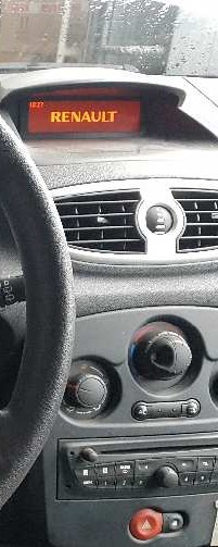
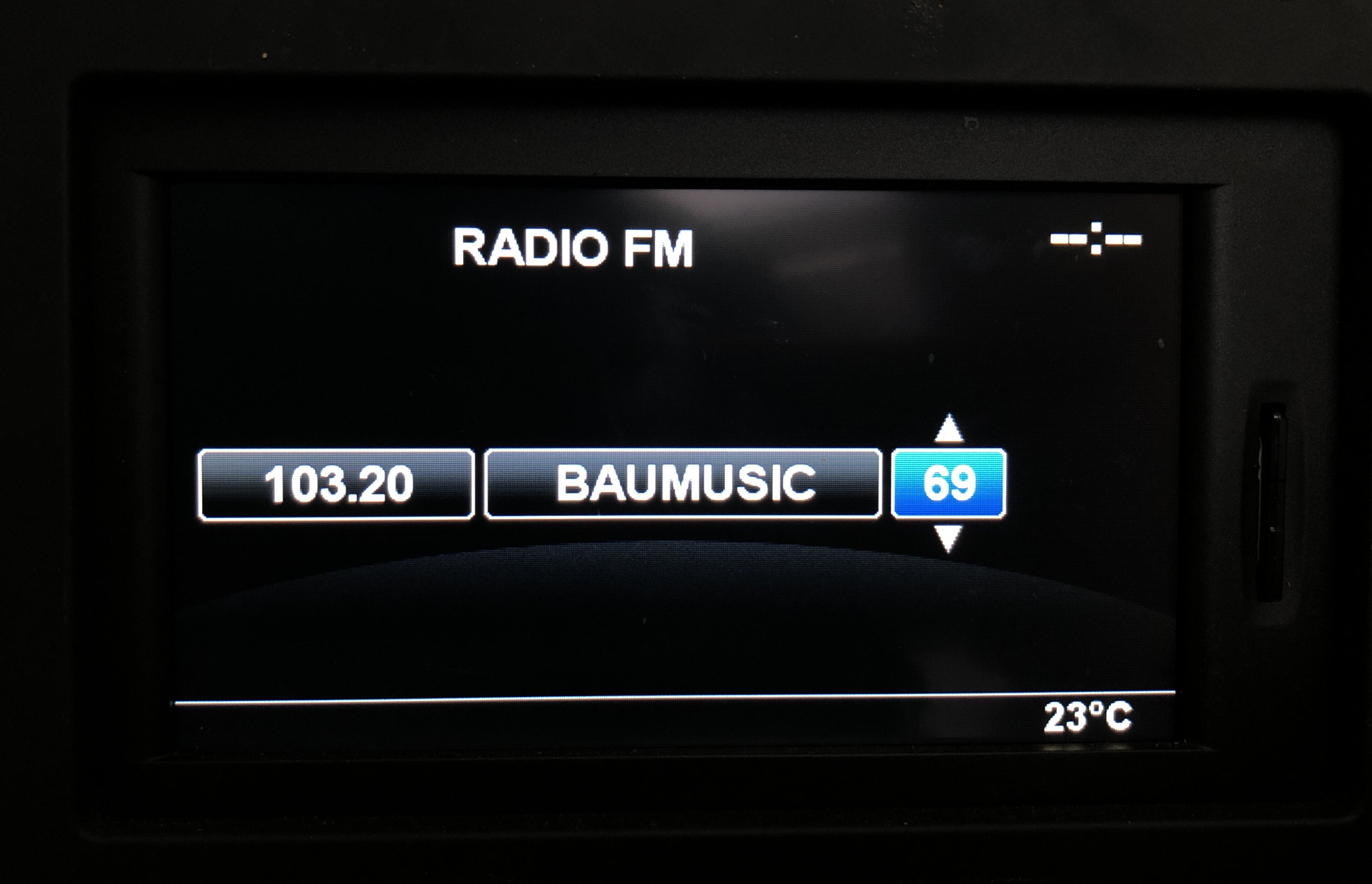
In short: If your display looks like this (or similar)it will most likely work. Note the bars above and below the row of text!
![]()
As i said on Scenic the Display is integrated into the Cluster and looks like this:
![]()
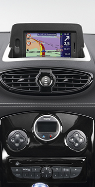
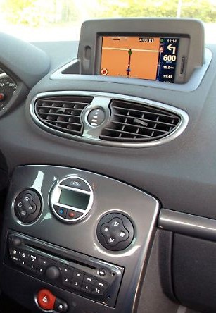
The third Option to use the Display data is to show it on the TomTom Navigation System wich looks like this:
![]()
I was amazed how much this protocol was used by Renault and decided that it might be really useful for a lot of people to know how to use this in projects.
As soon as you take out the original Renault Radio and replace it with something different the display is is unused. Or wouldnt it be really awesome to display some kind of information like a voltage or temperature? Or even a own menu structure to set things or make stuff happen? So much potential...
SO i started to order some Hardware to reverse engineer all of this. And the fun begun.
The tools i use i will discuss in the next episode of this blog. We will focus here on the Car Hardware.
Because i i didnt know all the details i described above i started to order random Renault Radios from around the time renault made the megane 3.
And i also ordered a scenic 3 cluster from 2013... because it was the cheapest one i could find for around 20 Euros. Wich looks like this:
The price range for scenic 3 clusters is amazing... from basically nothing to "are you kidding me" ... Some sellers think that a TFT Display from a 14 year old car that sold A LOT of units is still worth 200+ Euros... But... lets just continue with the story.
The first Radio i got for my experiments was a from Renault Laguna.
It looked quite similar to the Radios from Megane and it was again the cheapest one of the radios that looked similar to the ones i need.
(How i got the scenic cluster running will be another Blog.)
I connected everything together and ... Nothing.
Nothing isnt quite right... The hardware seemed to do nothing but on my Can Bus monitoring software i saw that there was some activity. So it must be connected right. The Radio started to send something and the cluster responded. But nothing more happened when you pressed buttons on the radio or the radio remote.
Ok. My fault. I should not order stuff that "looks similar" to what i need. Lesson learned. Order the next radio. This time i ordered one from a Megane 3 from 2009. Wich is exactly what i need.... I foolishly...
Read more -
Harvest parts from cars?!
06/05/2023 at 16:41 • 0 commentsIsn´t it a shame that perfectly good stuff gets thrown away?
Thats especially true in the car sector.
Once a car is slightly older and or breaks, we tend to throw away the whole product.But a car isnt just a car... It´s a collection of wonderful high quality parts that
are waiting to find a new life. Buttons, Sensors, Mechanisms, Displays, Motors...
And all of these beautiful parts are hiding from you at your local scrap yard (or online).If you are not searching parts from a specific model you can find some seriously cheap
stuff that is often way better then you imagine.For me it started with just buttons. I needed some nice looking buttons for a project and
they needed to be big, comfortable to press and have a long life span.You should know how freakin´ expensive new stuff gets if you want higher quality.
I decided to go to my local scrap yard and ask if i just could look through the cars that are already scrapped to look for some cables and switches.
And indeed i could.
After several hours i came back with a small bag full of buttons, switches, interieur lights
and the connectors for them including some cables.
European brands around the 2000s and onward have a super nice quality of things the driver can interact with.But beware of the "soft touch paint" on some parts... it is turning into goop and is disgusting.
Double shot injection molded Parts are the best.
Some buttons are painted and they flake off after 20 years of use... Dont get those.![]()
Here i have two similar car radios. The upper one has double shot buttons and the lower one has painted buttons.
The crappy look of the painted buttons make the parts very cheap. I needed exactly that radio for reverse engineering the can bus. And because it looks like it looks it was the cheapest one.
Perfect for the things i need it for.
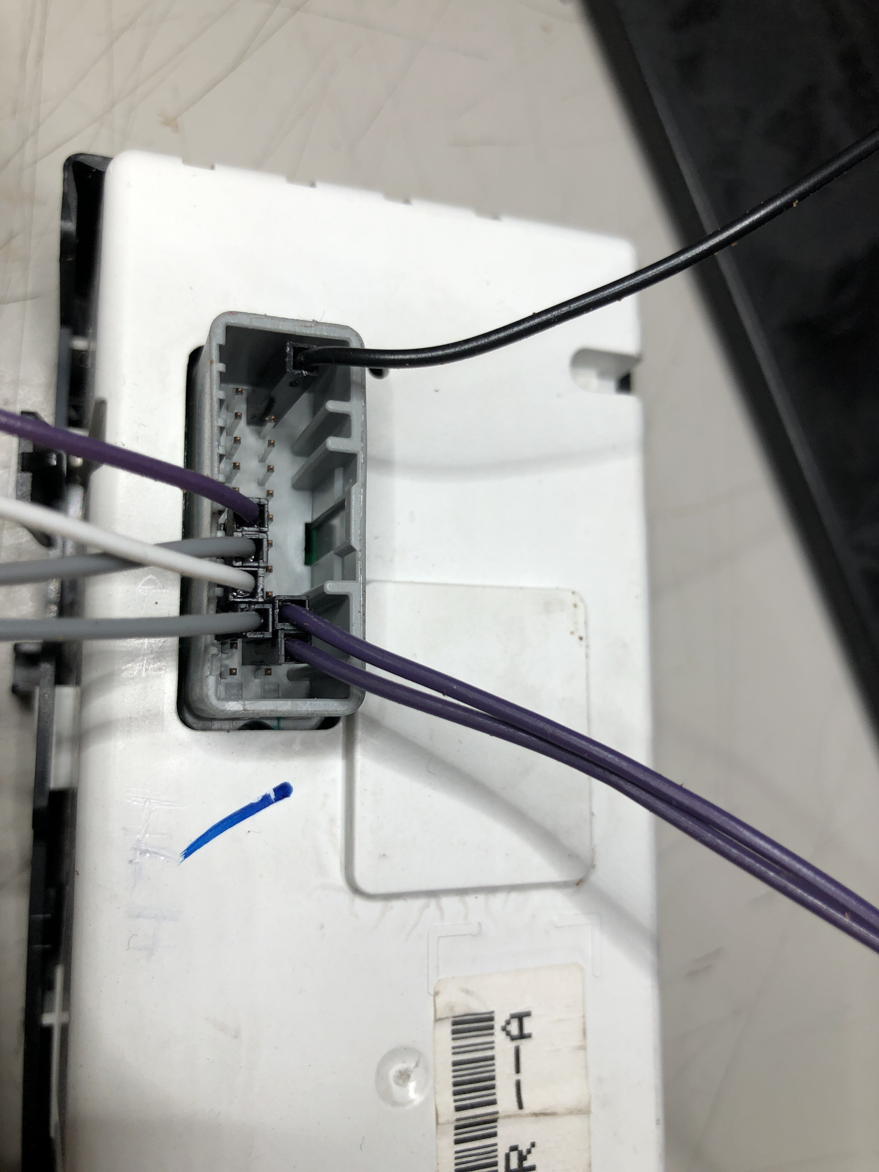
Tip : Always try to get the plugs with some cable for a thing that you want to use... it makes your life easier.
Most of the time you can just use jumper leads if you dont have a plug. BUT to have the right connector feels better. :)
And if you dont have shematics a plug with its colored cables may give you some hints how to connect it...
![]()
AND never forget some basic tools when you go to the scrap yard.
I always take my super cheap toolkit with me and a sidecutter for the cables.Most of the time you will need Torx from around 2000 and onward.
Sometimes a regular screwdriver is a better choice when the one from the toolkit is too thick.
Your phone is a pretty good flashlight ... remember that ;)
![]()
All this wonderful stuff made me so happy that i included the scrapyards around me as a parts bin...
Sometimes i have the feeling that this stuff made me more creative. You sometimes
have to work around limitations. Or you simply cant use a thing you really wanted to use and have to use something completely different.You can make this into a really fun adventure. You will learn a lot of interesting things
about electronics and mechanics.
And at the scrapyard it doesnt matter if you break something... But you will learn to get the things you want without brute force... :)
Because you often break exactly the thing you wanted in the process of ripping it just out...Even if you break things ... you can look inside... and probably understand how a switch with integrated LEDs work for example. You will learn in every way. :)
Over the years i got a lot of things from the scrap yard. Like a window lifter motor i used to automate a sliding door. Or an old tail light where i replaced the LEDs with WS2812 adressable LEDs to make it into "light object".
The Speakers you get there are also pretty descent depending on your donor...
And everything for super affordable prices compared to a new off the shelf solution.
Nearly all parts will use 12V to work. Thats perfect if you want to use an old computer power supply to get your parts going.Here i use a old...
Read more