 Est
EstTo make this sword I found easy and cheap to buy pre-made modules off Ebay/Aliexpress and mount them on a double side PCB . Here a picture of the modules and discrete components mounted on the PCB.
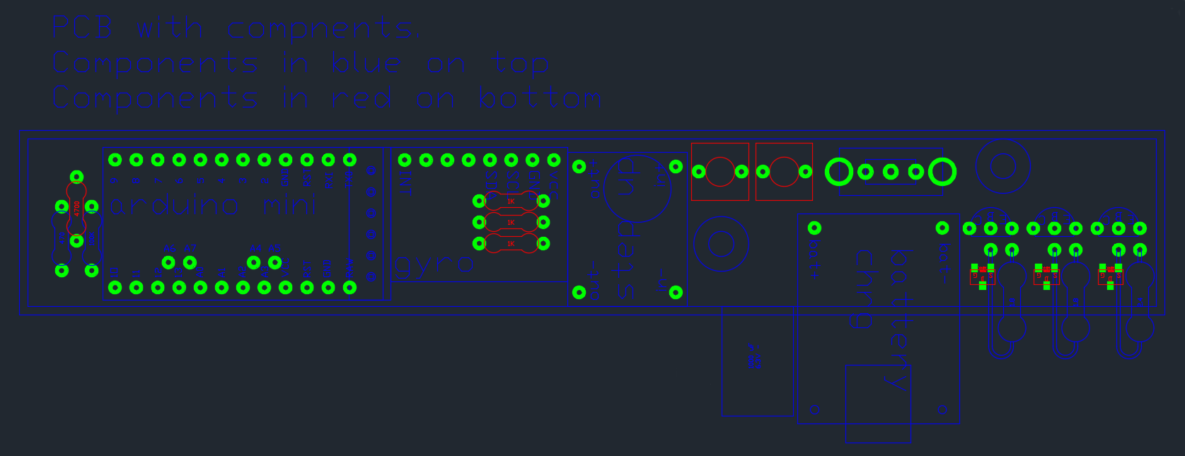
I designed the PCB with a mechanical CAD because i used the same CAD also to cut pockets in the acrylic to accommodate the modules and components. The PCB supplier i used for the prototype (layercircuit in Bangkok) accepts the PDF format for the PCB traces so I did not need to use a proper PCB software. In one week, this supplier made 2 pieces of this double sided PCB for 116 THB (3.3 $) plus 80 THB (2.3 $) for the delivery. This price is unbeatable but the pads/vias are not plated.
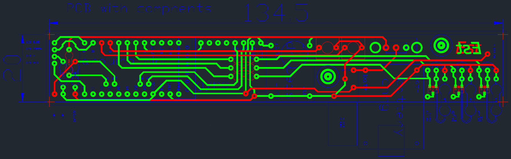
In the files section There is the PDF and CAD file to produce this PCB.
This sword is illuminated by a 3W RGB LED mounted off the PCB. The power LED is driven by a constant current driver that supply about 350 mA for each channel. The LED driver is made of a MOSFET, a sensing resistor and a BJT transistor. The value of the sensing resistor for each channel (RGB) is adjusted to obtain a white color when all the three channels are turned on for the same duty cycle. I found that a 1.8 Ohm resistor on the B and G channel and a 2.4 Ohm resistor on the R channel is the best compromise using standard resistor values.
To accommodate the power LED with the PCB heat sink in the sword i had to cut off the sides of the PCB. For this reason I considered safe to reduce the power consumed by the LED to 1W.
The power is supplied by a 3.6V 1100 mAh lithium battery that I got from an electronic cigarette battery. Ordering the electronic cigarette battery from Aliexpress is the cheapest way i found to get this slim and high capacity battery that can fit in the handle of the sword. A step up module converts the voltage to 5V and a charging module charges the battery at a rate of about 500 mA. Originally the charging module would supply 1A to the battery, but it would be too much for this battery so a resistor needs be to changed to adjust the charging current. To do this i replaced the SMD resistor marked in red in the picture with a 2.2 K trough hole resistor.

The color sensor is based on this instructable i found:
http://www.instructables.com/id/Using-an-RGB-LED-to-Detect-Colours/
A RGB led illuminates the surface to be detected one colour at time, and a LDR senses the amount of light reflected back.
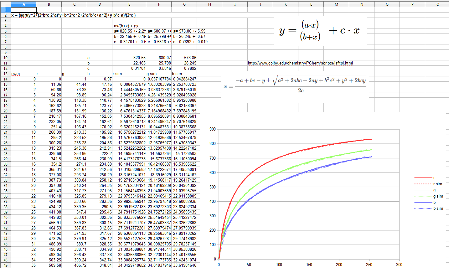
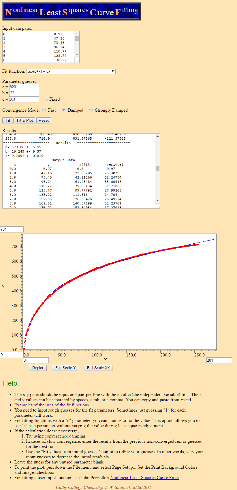
I tweaked the code a bit as i found that i get a better color recognition if I linearize the response of the phtoresistor (that is connected in series with a resistor). To obtain this graph I applied a white paper at the end of the word, i modulated the 5mm LED in PWM and i recorded the data from the photoresistor. The values in Y are the ADC readings and the values in X are the PWM values. I found a formula that that matches that characteristic and it's coefficients for each of the three channels. A free software online helped me to find the coefficients that almost perfectly matches my curve. According to this graph the sensor (RGB led + LDR) is more sensitive to the red color, this because all three channels inside the RGB led share a common resistor and when the red channel lights up it draws more current than the green and blue because it has a lower forward voltage.
The sword lights up the RGB led according to the mode selected using the two pushbuttons, if both buttons are pressed at the same time the sword detects the color and lights up.
At first i create a routine that lights up only one led channel R,G , B for time because i was afraid that a high current drawn could disturb the power supply, but when i swing the sword fast i can see the single channels light up and the light does not mix. With the routine i made at first the pwm was about 250 Hz. After that i changed to used the Arduino function pwm that lights up all the channels at once and with a faster pwm frequency. I had to redesign the PCB as the first routine did not use native PWM pins on the Arduino.
Video og the...
Read more »


 Saimon
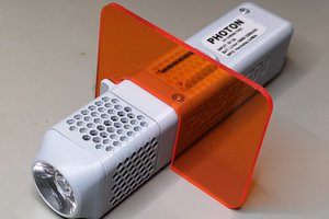
 Mile
Mile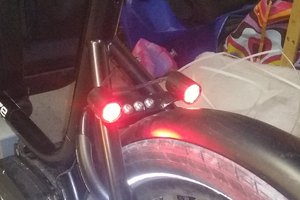
 cheperboy
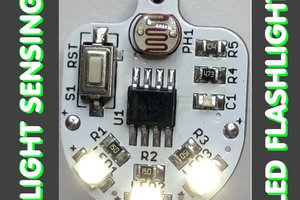
the inscription(อิคคิว) is catching my eye. * *