Sounds like a great hack!
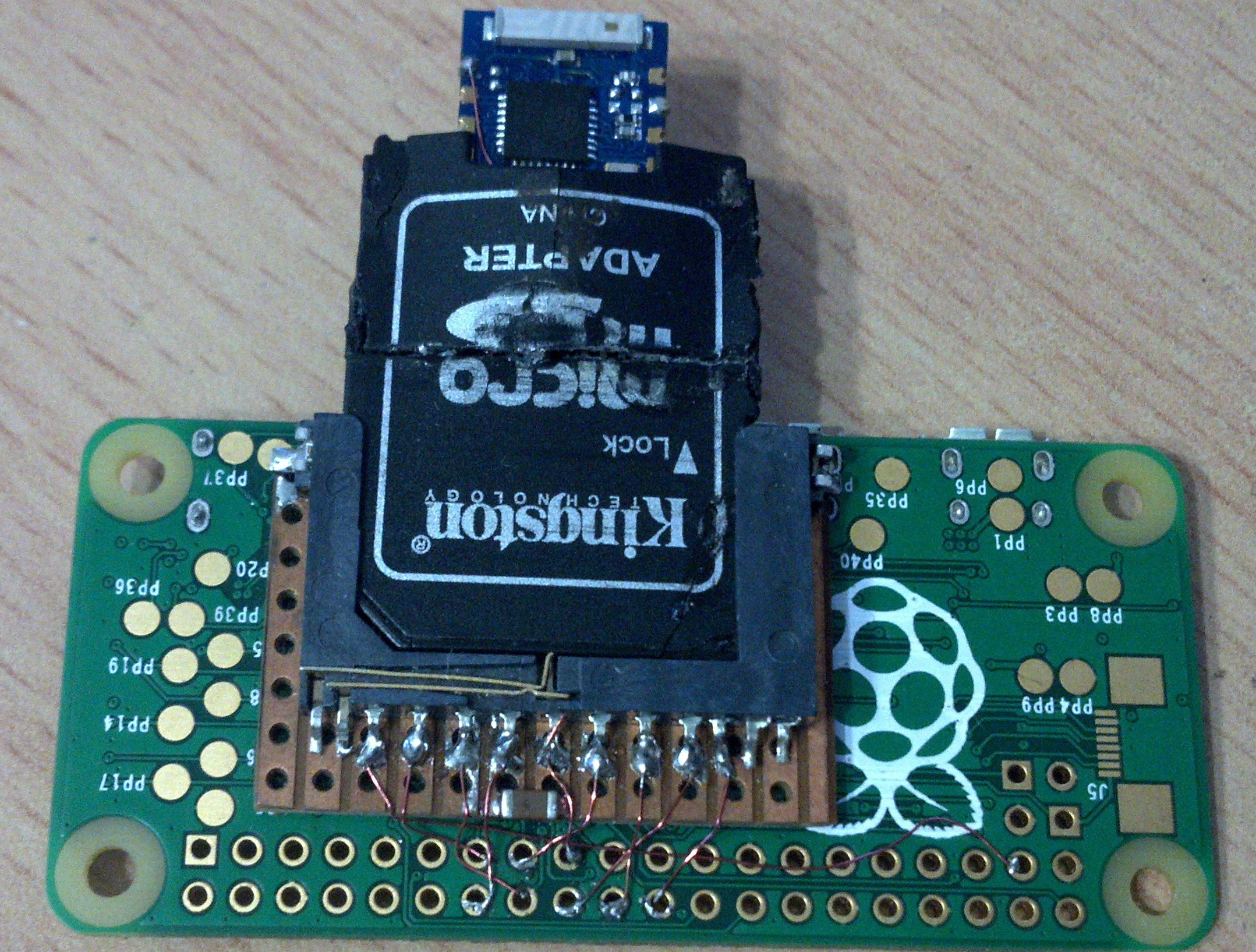
Inspired by @ajlitt's #RPi WiFi (and I refer you there for instructions on building the kernel module etc), this project grew from a hasty implementation of the basics required by mounting an SD card slot on the back of a Pi Zero, with an ESP-03 mounted on a micro-SD adapter card:
 This worked well, and I found having the option to remove the WiFi & insert memory card handy.
Re-inserting the WiFi would cause the Pi to freeze, and I soon found that executing
sudo modprobe -r esp8089
prior to re-insertion would allow the module to reload & WiFi come back up.
To have this done automatically, a udev rule was created in /etc/udev/rules.d/60-esp8089.rules to unload the kernel module on removal of the WiFi card:
ACTION=="remove", KERNEL=="wlan0", RUN+="/sbin/modprobe -r esp8089"That was fine, but one issue remained - after issuing a "sudo reboot", the esp8089 WiFi would not come back up. I realised this was because the module still had the firmware on-board, uploaded by the previous linux kernel module's two-stage initialisation. I could see no way round this, bar simulating what I was doing in practice, namely briefly pulling the card out & re-inserting it.
Pi, tell me you're booting.
This need set the ball rolling on adding components to power-cycle the socket at every reboot. But how to detect that the Pi is rebooting? Was there a signal, with luck on the 40-pin header, which would show that the Pi was commencing the boot process?
It dawned on me that I could (mis-)use the HAT eeprom polling, done once only by the videocore VPU, before linux is even started. I connected my logic analyser and saw a low-going pulse train of ~3.5ms on both ID_SC & ID_SD, even when there was no HAT connected, and before the rainbow splash screen was drawn. Bingo!
I bread-boarded a simple pulse-stretching design based on an RC delay, and found that 330nF & 1M, with a couple of FETs to get a nice square pulse of ~300ms with the correct logic level, proved to work well.

My next challenge was to add an ESP-12E/F module alongside the SD slot, and see if they could co-exist somehow...
Multiple cards on the SDIO bus?
I was encouraged on reading this thread that I could simply parallel up a second device & have it work, the last post in that thread claims up to 40 cards on the MMC bus! Yeah, this is SDIO, not MMC, but worth a shot.
Alas no, one memory card or the other would work, whichever was inserted first, but at least the second card didn't interfere with operation of the first. While searching ebay for old SDIO peripherals I might try in the card slot, I noticed the TXS02612 SDIO port expander, pretty much a six-pole double throw switch for the signals. That there even was such a thing ended my hopes for two devices working at the same time on the SDIO bus.
As an aside, ebay also threw up this interesting card, a combo WIFi & micro-SD device. Pretty much what I was striving for, but not an option at that price, or as much fun, compared with the esp8266 hack.
So, back to my stacked SD sockets & the two memory cards. I snipped the Vdd wire to the working card, and smiled broadly when the other card popped up on the Linux desktop. It later turned out I should have investigated this more thoroughly, but that was enough for me to start putting a design together. The plan was simple - use the card-detect switch on the socket to turn off the esp8266 power in the same way as I'm employing ID_SD.
Learning KiCad.
What a pleasure that turned out to be - I could get hooked on this. With the aid of a few youtube tutorials I was soon up & running. I implemented jumpers here & jumpers there for socket only, esp & socket, 1-bit & 4-bit operation etc That was at a time before @ajlitt had vastly simplified things by noticing that the module's spi flash could be relied upon to sit dormant while connected to the SDIO bus's shared pins. Any next revision will be a lot neater layout-wise because of that!
It seemed the obvious choice to have the ESP-12E/F hang off one end or the other of the Pi Zero. The Espressif hardware design guide mentioned keeping things away from other high-speed buses, so with micro-SD & HDMI both on one end of the Zero, the other end seemed the better.
Striving for as thin a pants style board as possible, I chose to cut out the PCB to allow the module to sit flat against the Zero too. That put the module's pads right over RUN header & other exposed pads, so some insulation would be needed. Die-cutting labels is part of my business, so that was easy for me. Better still, I could sandwich in a copper ground plane covering the whole area, insulating it with plastic both sides.
Choosing to site the SD socket as centrally on the long edge as the module would allow, was done for aesthetic reasons, and to get as far away from the HDMI as possible. This left unused PCB space on the opposite edge to the module, which couldn't go unused. Relocating the data micro-USB there would have three benefits: less hindered access to any SD card, less metal near any WiFi antenna, and a nice "stick" format when powering from the short edge. Furthermore, I could include yet another solder bridge to configure the socket without the 5V VBUS connected - perfect when occasionally connecting to a GPIO-powered Pi in gadget (serial, ethernet) mode to configure it etc.
The Zero's D+ & D- are handily accessible on the under side as PP22, PP23 respectively. Taking advantage of the flush back-to-back mounting, a couple of precisely placed tiny PTHs would allow quick hook-up of those with solder alone. A cut-out on the insulating ground-plane enabled that, and the absence of insulation around the lower HDMI pins would permit the ground plane itself to be connected.
I'm not sure the ground plane improves signal integrity - I would have to build one without it to test - but I have seen that WiFi performance is hit badly if the board is mounted conventionally on the top side without it.
The Long Wait.
As this would be my first foray into PCB production beyond hand etched & drilled, single-sided one-offs made in the old days, I spent a good while checking, re-checking & polishing things. A local prototype PCB manufacturer was chosen, and their no-rush service knocked 25% off the price. Going 0.8mm meant I had to have a full panel made, 48 in total. So be it.
The first board was hastily assembled and tested. It was nice to see the SHABPi's power LED dip on HAT EEPROM polling, causing a second flash of the ESP-12F's blue LED. A little while later I witnessed the sequence of three blue flashes, & I knew all was good with the add-on.
At this stage the SD socket was not attached - a design flaw meant that pre-assembling the board with the SD socket soldered in place would cover the PTHs needed to connect USB to PP22/23.
Disappointment.
On adding the socket, I inserted a memory card & watched the WiFi drop out as planned. But the memory card itself went unrecognised. I never had tested module + card in this fashion, only memory card + memory card. Oh well, with those jumper options installed, I can still configure it module or card.
Slightly deflated, I built and tested a few more boards. The Zero with SDIO WiFi makes the perfect partner to some of my mbed projects - the STM Nucleo boards can be re-programmed remotely, and the ttyACM0 USB2Serial can be used for remote logging & interaction.
I was resigned to the fact that I would have to use the TXS02612 & my attempt at a cost-saving hack was doomed.
Bodge Wire to the Rescue.
After a couple of weeks the itch that was the non-working switch needed scratching. In the first place I tried maintaining power to the module & disabling it by pulling CH_PD low on card insertion. Same result as pulling the power, no good. There was one last thing to try - holding the module in reset: pulling RST low.
One bodge wire on the under-side where it won't be seen, tucked in the sandwich, was added and hey presto, I winessed the WiFi drop out & the memory card pop up. Relief & joy!