Close
0%
0%

Minimalist A-go-go

A project inside Attiny. I will not step out for larger one till I complete it.

Similar projects worth following
I've tried to trace the computer history, from making TTL 4bit CPU and 6809, 6502, and Z80, where I noticed nowadays we have much easier way to learn from root! It's just by 50JPY Attiny!
I decided to learn from root, especially by AVR Assembly on Attiny 13, utmost Attiny85. This project will show you just my learning process, and I am not sure it is useful, but I will go, A-go-go!

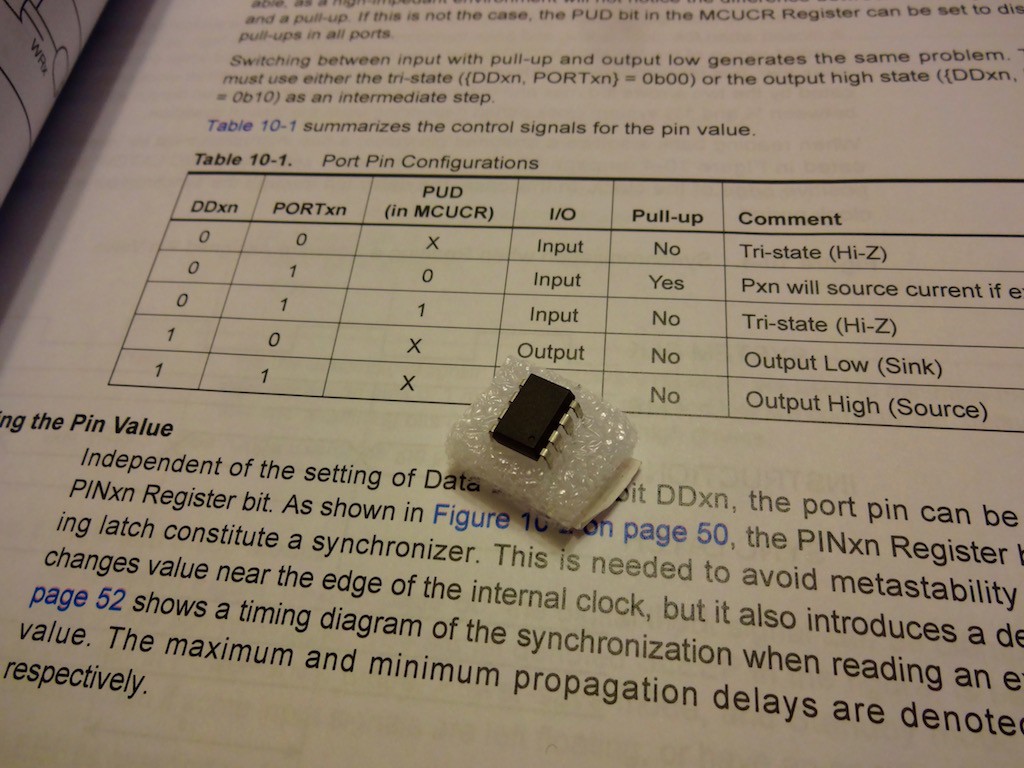
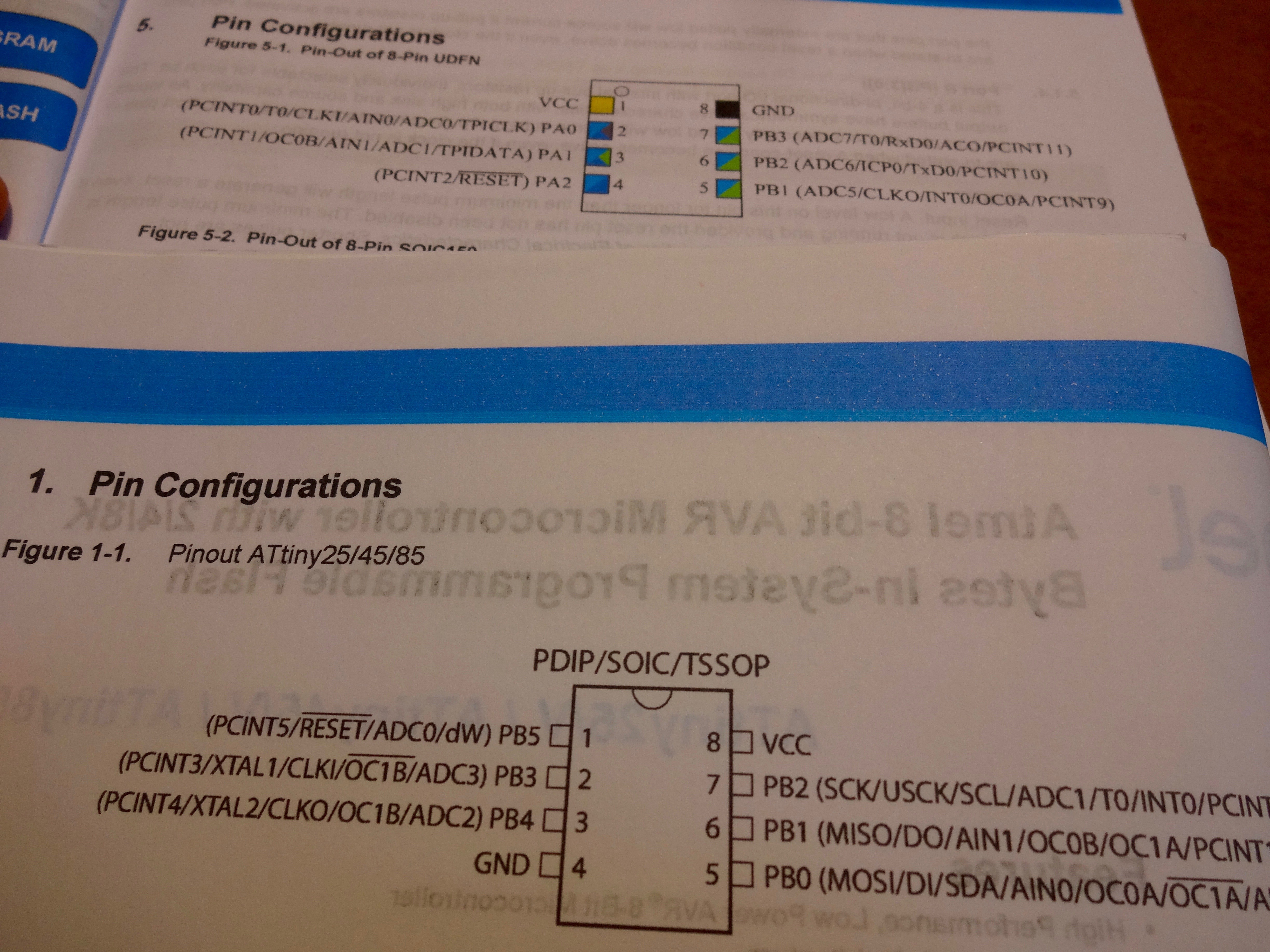
We can find lots information regarding AVR and its command. But most useful one is data sheet by Atmel.

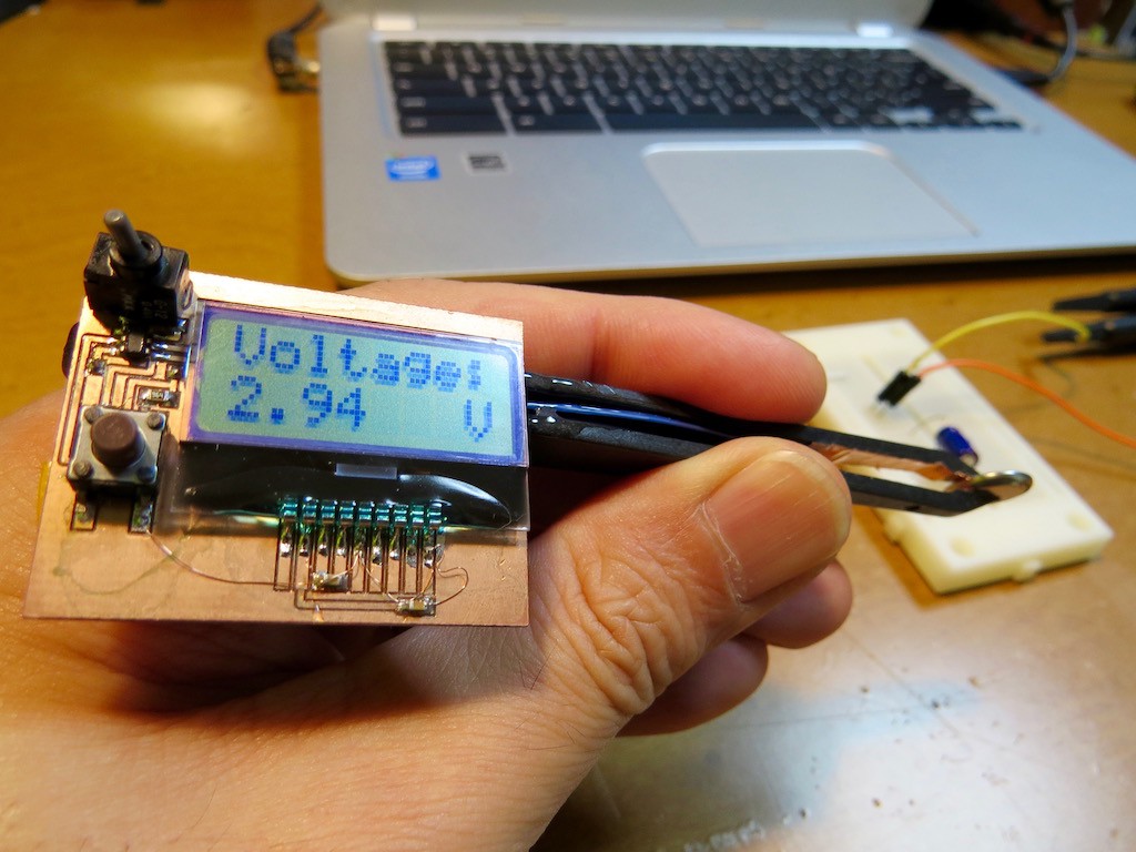
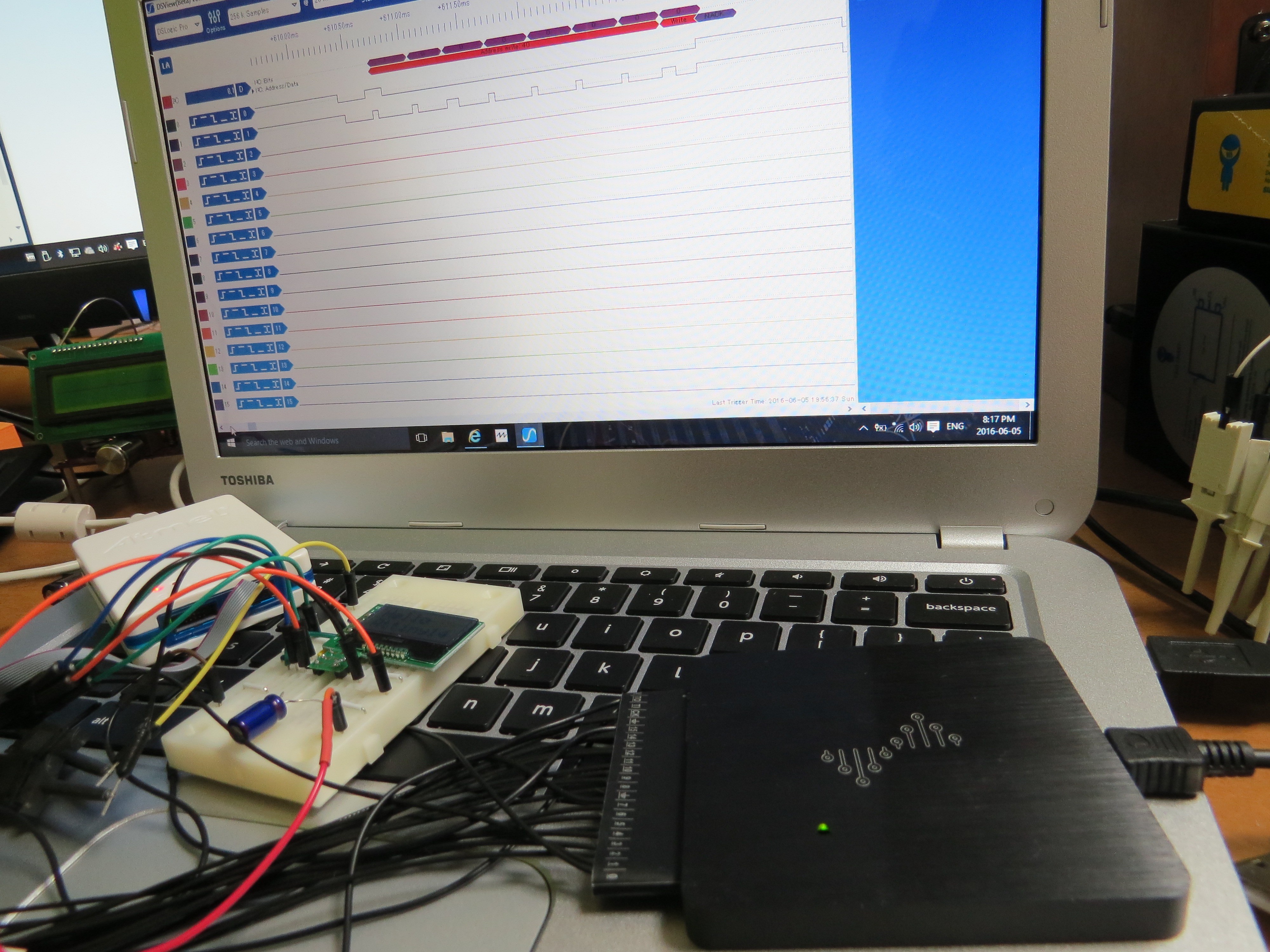
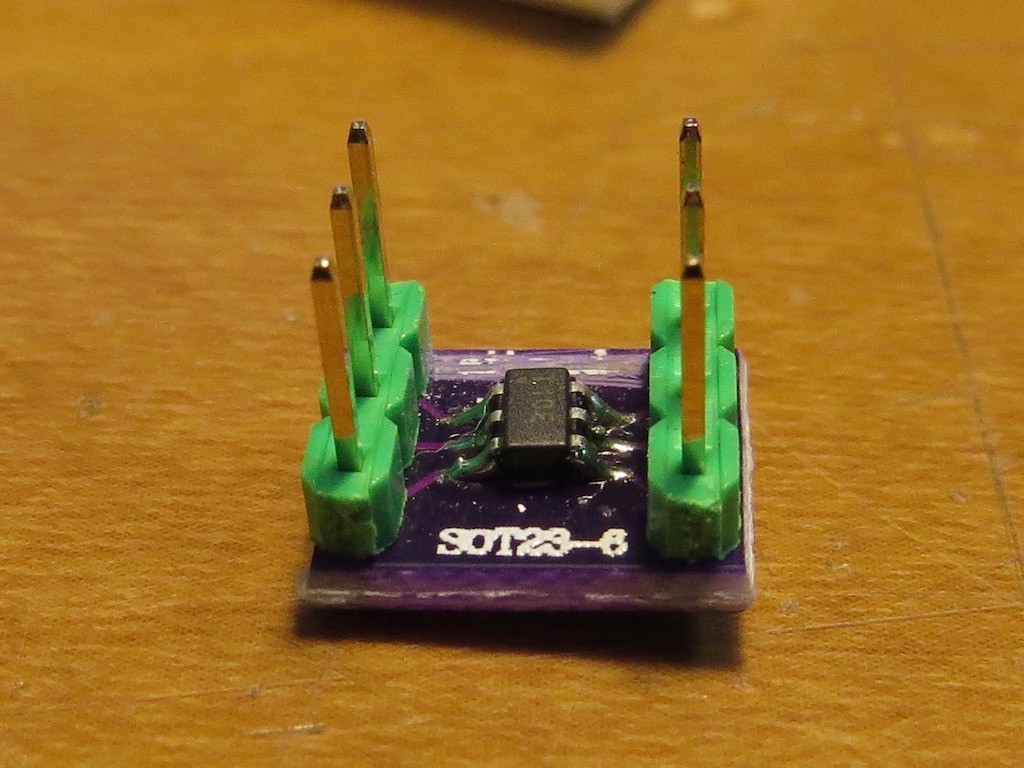
One more important and easy tool for programming is Atmel ICE.

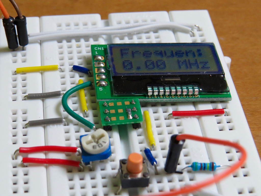
Just connecting Attiny and Atmel ICE will be enough to test it. (Atmel ICE is not necessary but it can also handle SAMD ARM series. Quite useful!)

So..... let's go!

  • 1 × Atmel Attiny13
  • 1 × Atmel ICE
  • 1 × Bread board
  • 1 × 10k ohm for pull up RST

  • Turning my page from ATtiny10 to new one

    kodera2t06/26/2016 at 13:16 0 comments

    As same as all of my previous creation, I myself feel I've almost fully utilise the function of tiny ATtiny10 SOT23-6 package and I completed "Super Tweezers" frequency and voltage measurement tweezers!


    As I presented before, all of function is done by ultra tiny wonderful ATtiny10! I am not sure when is the next time but on the next time I will step forward from SOT23-6 to SOP8 or 14, a bit more larger scale one.

    Actual operation can be found in the following movie... have fun!

  • Ultimate ? application of ATtiny10, freq counter & DVM just in one!

    kodera2t06/21/2016 at 12:54 0 comments


    I think it is quite close to "ultimate" application of tiny ATtiny10. Eventually two applications, frequency counter and digital volt meter is combined in just one code and its function can be switched by pushing switch ON or OFF as initial condition.

    Here is the schematic. Still super simple and just added one switch for PB2. Indeed PB2 is working as (1) function selector, (2) frequency counter input, and (3) DVM meter input. Surely we can buy very high precision DVM and frequency counter but I'm myself a bit surprised to see my realisation just 50 cents SOT23-6 MCU. (The above schematic contains some unmounted components, for example IN4148 protection diode...)

    And my assembly code eventually ( already released at github) approaches to the limit of ATtiny10, 1024 bytes (1 kB)....

    Segment   Begin    End      Code   Data   Used    Size   Use%
    ---------------------------------------------------------------
    [.cseg] 0x000000 0x0003ae    942      0    942    1024  92.0%
    [.dseg] 0x000040 0x000060      0      0      0      32   0.0%
    [.eseg] 0x000000 0x000000      0      0      0       0      -
    
    Again it is dirty and not well organised but surely working as multi-function instrument. Actual operation can be found in the following movie... Have fun!!

  • Eventually ATtiny10 becomes single chip frequency counter!!

    kodera2t06/19/2016 at 12:56 0 comments

    Who said ATtiny10 is "brain dead" ? In its data sheet we cannot find word I2C but we can add function as same as LED blinking. In addition, ATtiny10 has one 16 bit timer which can be driven by external clock. Naturally it will work as "frequency counter!" Here we have!

    Actually I had some accumulation of AVR assembly for these two months and this code is easily written after I2C bitbang completion.This is quick coding and not optimised but as same as before dirty code is released on github.

    My code occupies on flash as,

    "ATtiny10" memory use summary [bytes]:
    Segment   Begin    End      Code   Data   Used    Size   Use%
    --------------------------------------------------------
    [.cseg] 0x000000 0x000304    772      0    772    1024  
    [.dseg] 0x000040 0x000060      0      0      0      32  
    [.eseg] 0x000000 0x000000      0      0      0       0  
    slightly decreased by "welcome message on LCD" deletion.... still 300 bytes free!

    Actual operation can be found in the following movie... Have fun and let us believe "Tiny" power!

  • ATtiny10 supporting I2C LCD and A/D leads to super simple V-meter

    kodera2t06/18/2016 at 03:52 0 comments

    As I presented in the previous log, I2C supporting in ATtiny10 seems to be successful. This time I activate A/D converter of ATtiny10. Indeed, ATtiny10 supporting I2C LCD and A/D leads to super simple Voltage meter!!

    All you will need is ATtiny10 and I2C LCD. Nothing more. I made a assembly code, which contains lots of redundancy and non-nessesity part such as welcome message "Hello ATtiny10", and also voltage display part is NOT optimised yet but
    Segment   Begin    End      Code   Data   Used    Size   Use%
    --------------------------------------------------------
    [.cseg] 0x000000 0x00038c    908      0    908    1024  
    [.dseg] 0x000040 0x000060      0      0      0      32  
    [.eseg] 0x000000 0x000000      0      0      0       0  
    it can be still inside internal flash of ATtiny10.My dirty assembly code is released on github and actual operation can be found in the following movie. Indeed response is well acceptable for voltage measurement application (main concern is accuracy, though...) Anyway, have fun!

  • Bitbang of I2C on Attiny10

    kodera2t06/16/2016 at 11:00 2 comments

    I2C interface is quite useful for extension of small MCU, because it just consume two pins (CLK and DAT). The case of Attiny10, it does not support by its hardware but indeed more than five years ago, some people and guys succeeded to implemented in C. For me, assembly seems to be more straightforward and I made the code from scratch.

    Actually bitbang is a kind of "very fast LED blinking". If you can make LED blink program in some MCU, you will be able to implement I2C on it. For implementing it, for example, bit "1" and "0" coding is like this:

    bit_high:
    	ldi temp1, 0b00
    	out PORTB, temp1
    	rcall delay
    	ldi temp1, 0b01
    	out PORTB, temp1
    	rcall delay
    	ldi temp1, 0b11
    	out PORTB, temp1
    	rcall delay
    	ldi temp1, 0b01
    	out PORTB, temp1
    	rcall delay
    	ldi temp1, 0b00
    	out PORTB, temp1
    	rcall delay
    	ret
    	;cl=1 da=0
    bit_low:
    	ldi temp1, 0b00
    	out PORTB, temp1
    	rcall delay
    	ldi temp1, 0b00
    	out PORTB, temp1
    	rcall delay
    	ldi temp1, 0b10
    	out PORTB, temp1
    	rcall delay
    	ldi temp1, 0b00
    	out PORTB, temp1
    	rcall delay
    	ldi temp1, 0b00
    	out PORTB, temp1
    	rcall delay
    	ret

    Here PB0 is SDA and PB1 is SCL of I2C. It is LED blinking, isn't it? If you have logic analyser (not expensive one but just a handy USB based analyser, in my case...) , actual timing and logic level can be confirmed and quite useful for completing bitbang.

    This is the LCD display driven by bit banged Attiny10. Currently my assembly code occupies,
    Segment   Begin    End      Code   Data   Used    Size   Use%
    --------------------------------------------------------
    [.cseg] 0x000000 0x0001e6    486      0    486    1024  
    [.dseg] 0x000040 0x000060      0      0      0      32  
    [.eseg] 0x000000 0x000000      0      0      0       0  
    Just 48% of flash and zero SRAM consumption yet (everything is processed in registers). My code (I am so sorry but it is quite dirty and redundant and no-sophisticted) is released on github, again it is combination of "LED blinking".

    Actual operation can be found in the following movie.. have fun!

  • Overclocking ATtiny10 !?

    kodera2t05/04/2016 at 08:47 0 comments

    So my lovely ATtiny10 is capable of processing lots job and at this moment, I have no complaint about its processing speed. But I noticed the default clock speed is 1MHz, internal RC oscillator (8MHz) divided by 8. This is no novelty but I would summarise how to set it to 8MHz and even beyond by OSCCAL register.

    .def R_TEMP1, R16	
    ; setting clock divider change enable
            LDI R_TEMP1, 0xD8
    	OUT CCP, R_TEMP1
    ; selecting internal 8MHz oscillator
    	LDI R_TEMP1, 0x00
    	OUT CLKMSR, R_TEMP1
    	LDI R_TEMP1, 0xD8
    	OUT CCP, R_TEMP1
    ; setting clock divider change enable
    LDI R_TEMP1, (0<<CLKPS3)+(0<<CLKPS2)+(0<<CLKPS1)+(0<<CLKPS0);
    OUT CLKPSR, R_TEMP1; set to 8MHz clock (disable div8)

    Just in order to change clock divider from 8 (default) to 1, these processes are required. Putting 0xD8 to CCP register is required each step of CLKMSR and CLKPSR. Just inserting these code, the clock will be set to 8MHz.

    More another way to speed bump or up is usage of OSCCAL register. In data sheet, we can see

    the clock speed varies from 4 MHz up to around 15 MHz. I was a bit afraid of this modification since it may forget original calibrated number for OSCCAL by touching it but the OSCCAL is restored if our code does not touch OSCCAL.

    OSCCAL can be touched as follows.

    LDI R_TEMP1, 0xFF
    ; overclock (from 4MHz(0x00) to 15 MHz(0xFF))
    OUT OSCCAL, R_TEMP1
    If you need to recover to original calibrated state, just remove this code is enough....

    Actual operation can be found in the following movie (as an example by LED blinking..) Have fun!


  • Very short update: LED fade (not abrupt ON-OFF) by PWM at ATtiny10

    kodera2t04/10/2016 at 12:37 0 comments

    I would put very short update, regarding my PWM trial

    Corresponding ASM code is as follows. Indeed I greatly refer the C code at avrfreak and tried to convert to assembler by myself (so such a redundant code, ;-)

    .def temp1 = R16
    .def temp2 = R17
    .def count_L = R18
    .def count_H = R19
    .def final_L = R20
    .def final_H = R21
    .def temp3 = R22
    .def temp4 = R23
    .def temp5 = R24
    .def temp6 = R25
    .equ topnum = 1000
    .equ count_start = 0xff
    .equ count_end = 0x01
    .equ subnum = 0x01
    ; Replace with your application code
    setup:
    	ldi temp1, (1<<PB0)+(1<<PB1);
    	out DDRB, temp1
    	ldi temp1, (1<<COM0A1)+(1<<COM0B1)+(1<<WGM01);
    	out TCCR0A, temp1
    	ldi temp1, low(topnum);1111101000
    	out ICR0L, temp1
    	ldi temp1, byte2(topnum)
    	out ICR0H, temp1
    	ldi temp1,(1<<CS01)+(1<<WGM03)+(1<<WGM02)
    	out TCCR0B, temp1
    
    start:
        ;inc r16
    	ldi count_L, 0
    	ldi count_H, 0
    	ldi final_L, low(topnum)
    	ldi final_H, byte2(topnum)
    	ldi temp1, 0x01
    	ldi temp2, 0x00
    loop1:
    	add count_L, temp1
    	adc	count_H, temp2
    	out OCR0AL, count_L
        out OCR0AH, count_H
    
    	mov temp3, count_L
    	mov temp4, count_H
    	ldi temp5, low(topnum)
    	ldi temp6, byte2(topnum)
    	sub temp5,temp3
    	sbc temp6,temp4
    	out OCR0BL,	temp5
    	out OCR0BH, temp6
    	rcall delay
    	cp final_H, count_H
    	cpc final_L, count_L
    	brne loop1
        rjmp start
    
    
    delay:	; subroutine DELAY
    	ldi	temp3, count_end
    	ldi	temp4, count_start
    	ldi	temp5, subnum
    counter:
    	sub	temp4, temp5
    	cpse	temp4, temp3
    	rjmp counter	
    	ret
    Somehow this code realise "soft LED blinking" as shown on the top...

  • Very brief review of ATmel's new ATtiny 102

    kodera2t04/10/2016 at 09:20 4 comments

    Fortunately I got very recent ATmel MCU ATtiny102 and quickly tried to program RGB LED blinking through ATmel Studio. I found several differences from conventional 8-pin AVRs in every aspect.

    (1) programming method is NOT SPI but TPI

    So far, 8-pin AVR was programmed by SPI (MOSI/MISO/CLK/RESET..) but this new 102 accept only TPI, which is same as ATtiny10.

    (2) Pin assign is completely different!!!

    As shown in the above picture ATtiny102 (up) has 1-pin VCC and 8-pin GND. This is totally different from conventional pin assign (which was totally pin compatible in 8-pin AVR series, ATtiny 13 to 85). We need a bit care for initial prototyping test.

    (3) New 102 has two output ports PORTA and PORTB

    I guess, ATmel uses same chip for 102 and 104 (simply most of ports are not wired in 102) and as a result 102 has two ports. This means, little source modification is required from conventional 8-pin AVR to 102.

    (4) Additional voltage reference (1.1 V, 2.2 V, 4.3 V) for A/D converter

    Voltage reference can be selected by REFS1 and REFS0 in ADMUX. Some ATtiny has 1.1 and 2.56 V reference but they has some limitation, requiring external capacitor. But the case of 102/104, it is completely free of charge.

    (5) USART and USARTSPI (functions exclusive) supported

    Not bit-banged but serial and SPI (one of them) are supported..

    As for programming, ATmel Studio has already supported ATtiny102/104 and we don't need to wait for something.

    Actual operation can be found in the following movie...

  • Joy in 1cm sq. board by ATtiny10

    kodera2t04/06/2016 at 11:47 0 comments

    And I am trying even more smaller MCU, ATtiny 10, actually its size is identical to general switching transistor. But even in such a small package, it has 4ch 8bit A/D converter with 1024 words flash memory. 6pin is not enough to support full SPI writing but there is a special way, TPI (details can be found in websites) but we don't need to worry about TPI. ATmel Studio with Atmel ICE fully supports its programming.

    Here is actual prototype board putting ATtiny10 for 6-pin dip break out. On the surface....

    Two LEDs and resisters are put to organise "voltage indicator"

    This is a actual wiring information between ATtiny10 and ATmel ICE. MOSI has no connection but binary transfer is supported by Atmel Studio.

    The following simple assembly code enables tiny voltage indicator...

    .def r_temp1 = R16
    .def r_temp2 = R17
    .def r_temp3 = R18
    
    .equ lv_1 = 0x40 ; values for voltage comparison
    .equ lv_2 = 0x80
    .equ lv_3 = 0xC0
    
    setup:                
    ldi	r_temp1, ((1<<ADEN)+(1<<ADSC)+(1<<ADATE)+(1<<ADIE)+(0<<ADIF)+(1<<ADPS2)+(1<<ADPS1)+(1<<ADPS2))
    out   ADCSRA,r_temp1       
    ;starting A/D conversion (free running mode)
    ldi	r_temp1, ((1<<MUX1)+(0<<MUX0)) ; input A/D = PB2
    out   ADMUX,r_temp1
    ; setting PB2 for A/D input
    ldi	r_temp1, ((0<<DDB2)+(1<<DDB1)+(1<<DDB0))
    ; PB0 and 1 are LED out
    out	DDRB, r_temp1 
    ; PB0, 1 for LED output (PB2 for input)
    
    main: ; main loop start!
    in    r_temp1,ADCL        
    ;reading lower bit of A/D result
    
    cpi r_temp1, lv_1 ; comparing measured result with lv_1=0x2b
    brlo s_vchk_1 ; if the measured value is lower than 0x40, jump to s_vchk_10
    
    cpi r_temp1, lv_2 ; comparing measured result with lv_2=0x80
    brlo s_vchk_2
    
    cpi r_temp1, lv_3 ; comparing measured result with lv_3=0xC0
    brlo s_vchk_3
    
    rjmp main ; closing main loop
    
    s_vchk_1:
    	ldi r_temp3, 0x00 ;all LED are off (positive logic)
    	out PORTB, r_temp3
    	ret ; return to main loop
    
    s_vchk_2:
    	ldi r_temp3, 0b00001 ;PB0 is on
    	out PORTB, r_temp3
    	ret ; return to main loop
    
    
    s_vchk_3:
    	ldi r_temp3, 0b00011 ; PB0, 1 are on
    	out PORTB, r_temp3
    	ret ; return to main loop
    "ATtiny10" memory use summary [bytes]:
    Segment   Begin    End      Code   Data   Used    Size   Use%
    ---------------------------------------------------------------
    [.cseg] 0x000000 0x00002e     46      0     46    1024   4.5%
    [.dseg] 0x000040 0x000060      0      0      0      32   0.0%
    [.eseg] 0x000000 0x000000      0      0      0       0      -
    Assembly complete, 0 errors. 0 warnings
    According to Atmel Studio, Attiny10 is well enough to accommodate my short code and still has lots of room! (Seems just 4.5% of capacity is using...)

    Actual operation can be found in the following movie... have fun!

  • Very primitive voltage indicator by Attiny13

    kodera2t04/03/2016 at 07:11 0 comments

    I am still in wonderful Attiny world, where I have learned lots of fundamentals of computer itself. This time I made a very simple and primitive voltage indicator by LEDs utilising A/D converter of ATtiny13.

    As it is, ATtiny is 8-pin MCU and VCC, GND and RST ( I am still beginner, and cannot hand it away) total 3-pins are already occupied. So I used the rest 5 pins as, PB3 (pin 2) for A/D input and LEDs are driven by 4-pins by PB0, 1, 2, and 4. I am enjoying assembly language, since I can see and understand very fundamentals and the code is written by AVR assembly as follows.

    ;
    ; webADCattiny13.asm
    ;
    ; Created: 4/1/2016 12:52:26 PM
    ; Author : kodera2t
    ;
    .def r_temp1 = R16
    .def r_temp2 = R17
    .def r_temp3 = R18
    
    .equ lv_1 = 0x2b ; values for voltage comparison
    .equ lv_2 = 0x56
    .equ lv_3 = 0x81
    .equ lv_4 = 0xac
    .equ lv_5 = 0xd7
        
    setup:                
    ldi r_temp1, ((1<<ADEN)+(1<<ADSC)+(1<<ADATE)+(1<<ADIE)+(0<<ADIF)+(1<<ADPS2)+(1<<ADPS1)+(1<<ADPS2))
    out ADCSRA,r_temp1 ;starting A/D conversion 
                         ;(free running mode)
    ;ldi r_temp1, ((0<<REFS0)+(0<<ADLAR)+(1<<MUX1)+(1<<MUX0))
    ;Vcc as analogue reference (currently commented out)
    ldi r_temp1, ((1<<REFS0)+(0<<ADLAR)+(1<<MUX1)+(1<<MUX0))
    ;internal 1.1V as analogue reference
    out ADMUX,r_temp1 ; setting PB3 for A/D input
    ldi r_temp1, (1<<DDB4)+(0<<DDB3)+(1<<DDB2)+(1<<DDB1)+(1<<DDB0)
    out DDRB, r_temp1 
    ; PB0, 1, 2, 4 for LED output (PB3 for input)
    
    main: ; main loop start!
    in r_temp1,ADCL ;reading lower bit of A/D result
    in r_temp2,ADCH ;this program uses lower 8 bits only, therefore the comparing results will be periodical for input voltage variation
    
    cpi r_temp1, lv_1 ;comparing measured result with lv_1=0x2b
    brlo s_vchk_1 ; if the measured value is lower than 0x2b, jump to s_vchk_10
    
    cpi r_temp1, lv_2 ;comparing measured result with lv_1=0x56
    brlo s_vchk_2
    
    cpi r_temp1, lv_3 ;comparing measured result with lv_1=0x81
    brlo s_vchk_3
    
    cpi r_temp1, lv_4 ;comparing measured result with lv_1=0xac
    brlo s_vchk_4
    
    cpi r_temp1, lv_5 ;comparing measured result with lv_1=0xd7
    brlo s_vchk_5
    
    rjmp main ; closing main loop
    
    s_vchk_1:
    ldi r_temp3, 0b10111 ;all LED are off (negative logic)
    out PORTB, r_temp3
    ret ; return to main loop
    
    s_vchk_2:
    ldi r_temp3, 0b10110 ;PB0 is on
    out PORTB, r_temp3
    ret ; return to main loop
    
    
    s_vchk_3:
    ldi r_temp3, 0b10100 ; PB0, 1 are on
    out PORTB, r_temp3
    ret ; return to main loop
    
    s_vchk_4:
    ldi r_temp3, 0b10000 ; PB0, 1, 2 are on
    out PORTB, r_temp3
    ret ; return to main loop
    	
    s_vchk_5:
    ldi r_temp3, 0b00000; all LED are on
    out PORTB, r_temp3
    ret ; return to main loop	
    The generated hex file occupies 231 bytes in flash. We still have enough huge room in ATtiny13 !!!!! Actual operation can be found in the following movie... have fun!

View all 12 project logs

Enjoy this project?

Share

Discussions

danjovic wrote 11/21/2016 at 21:25 point

Impressive project!

  Are you sure? yes | no

jfmateos wrote 07/04/2016 at 18:30 point

Please, could you share the reference of that tiny I2C LCD?

Best regards,

  Are you sure? yes | no

kodera2t wrote 07/04/2016 at 21:57 point

I added I2C LCD controller link on the top page link of this project. Please take a look. Thank you!

  Are you sure? yes | no

ubi de feo wrote 07/03/2016 at 08:11 point

Great learning journey, very interesting way of picking up skills. 

The AVR is a great platform to learn, and it took me a few years to figure out a lot of the process, especially lacking knowledge of electronics, math, low level programming, but I think by now I have it pretty much figured out.

If you get the chance grab an AVR Dragon and you'll expand your knowledge of the platform even further. I love Atmel's chips even though some keep preferring PIC (which I know nothing about). Keep going, you're doing great :)

(While reading though your assembly I spotted a typo "precsaler")

  Are you sure? yes | no

kodera2t wrote 07/04/2016 at 21:57 point

Thank you for encouraging and useful comment. Actually I did not know "AVR Dragon" and I've used ATmel ICE only but will check it!

  Are you sure? yes | no

SrednaD wrote 03/19/2016 at 10:29 point

Hey!

Just want to tell you I will be following, and that it will be really useful for me as I am just starting to learn AVR C and was also hoping to get the basics of assembly when I'm at it. 

Awsome!

  Are you sure? yes | no

kodera2t wrote 04/10/2016 at 13:43 point

Sorry I completely overlooked your message. Thank you for encouragement!! Actually this project is showing just my learning process, but I am very happy if something is working well for you..!

  Are you sure? yes | no

Similar Projects

Does this project spark your interest?

Become a member to follow this project and never miss any updates