 Eric Hertz
(Update: Better Results with "Better Wire" + "Mind-Boggler" at the bottom. Ideas?)
Revisiting the joys of sdramThing1.0! Weee!
(I knew there was a reason I built the other versions on a soldered-breadboard!)
So, great, sending a column-number as *data* to the same (or a close) column *address* makes for nice read-back...
What doesn't...? Sending another number. Especially one that causes a change-in-value on several different address/DQ lines...
I've seen this before... sdramThing1.0 had this problem.
This is why the clock signal is shielded.
This is where the clock-signal is *not* shielded... on the breadboard:

So... Take it off the breadboard and run a shielded wire all the way to the clock. Then find out that the clock (which is driving both the SDRAM (4 chips!) AND the AVR) is still sensitive due to the Y-nature and, likely reflection. Then... The list goes on. Don't run that clock wire (even though it's shielded) near anything else, because there are exposed (unshielded) joints, and I was too lazy (and too afraid of ground-loops, which might not really be a problem) to solder up the shield to the SDRAM side...
Basically what you get is: Run that wire around in different angles and different locations until the data reads back correctly. Which, of course, means writing a little utility to send error-messages whenever data's not read-back as expected...
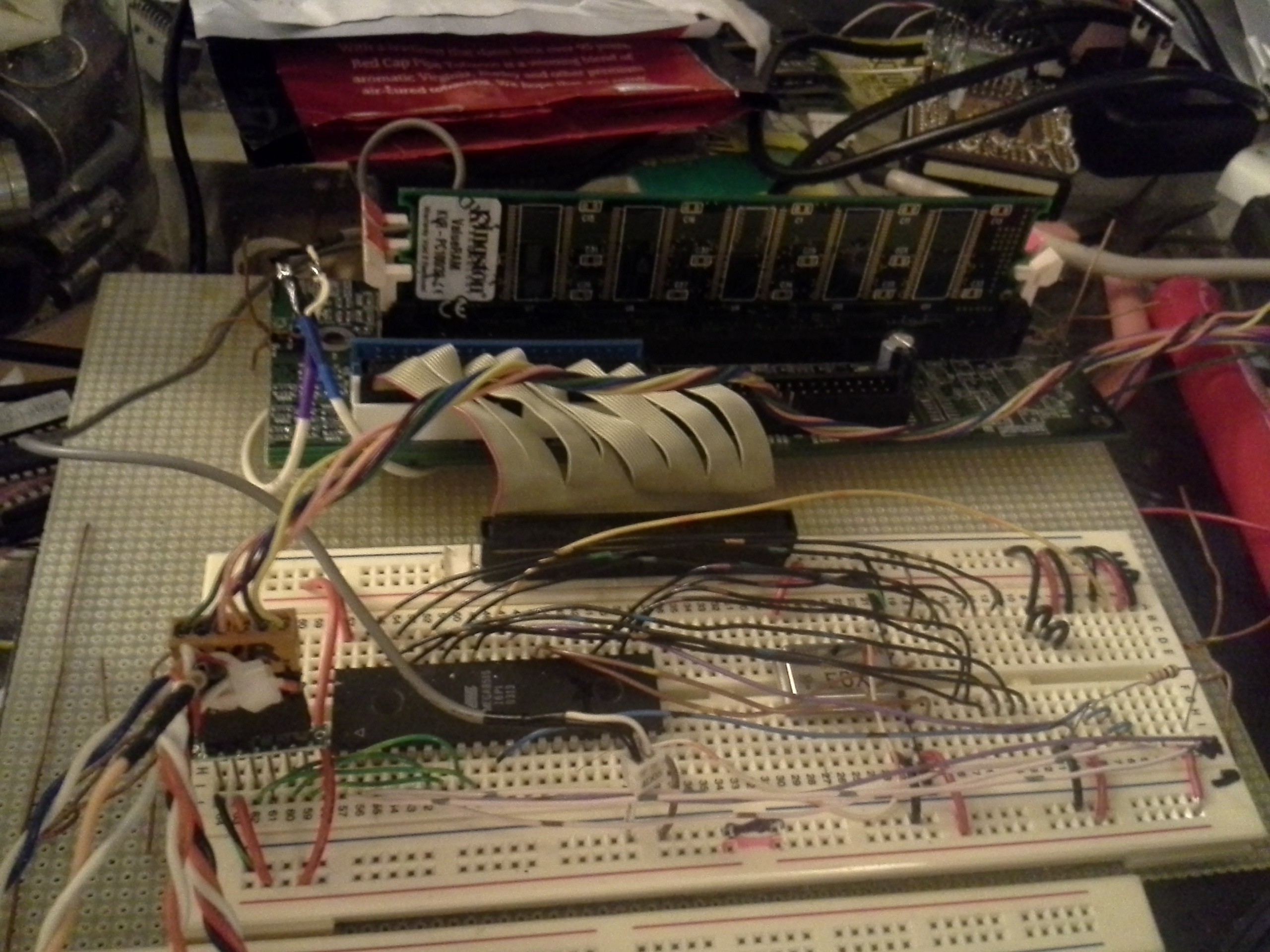
Note the big-long gray shielded clock-signal "routed" to the left and tied to the white shielded-wires (with blue and purple heatshrink).
Note also, the crystal-oscillator is now only attached at one point, to the AVR. The SDRAM is now attached at the AVR's XTAL pin... so, less of a Y, plausibly less reflection (but in NO WAY ideal. This thing will likely not work much faster than 16MHz).
I took a class and did an internship in high-speed digital oh.. a decade ago. I have a vague idea of ideal methods involving termination resistors and matched-impedance-traces and whatnot, and can probably stand to refresh myself... But frankly, I think, none of that stuff means squat when working with solderless breadboards and long "antennae." And it was kinda a "black art" at the time.
There are things that could be done... I originally relied on the IDE's 80-conductor cable to provide shielding, being that every signal wire is surrounded by a ground in the cable. But I didn't pinout keeping in mind nearby wires on a 40-conductor cable (which is essentially what my breadboard breakout looks like), which would be the signals on the opposite row of the 40-pin connector. If I had, those white wires, on the backside of the breadboard, would've been grounds surrounding that clock-signal. (The "upper" wires might've worked, as they're not running across the terminal-strips). Then, if I thought about it further, to have it laid-out such that the signals next to the clock, on the 40-wire connector (in the same row) are also grounds... such that the breadboard's "capacitors" (aka terminal-strips) would be grounds... That'd probably do wonders, but would require *four* ground-pins surrounding the clock pin! Then, maybe, just a shielded breadboard-jumper would maybe do... I dunno if I've the patience for that right now.
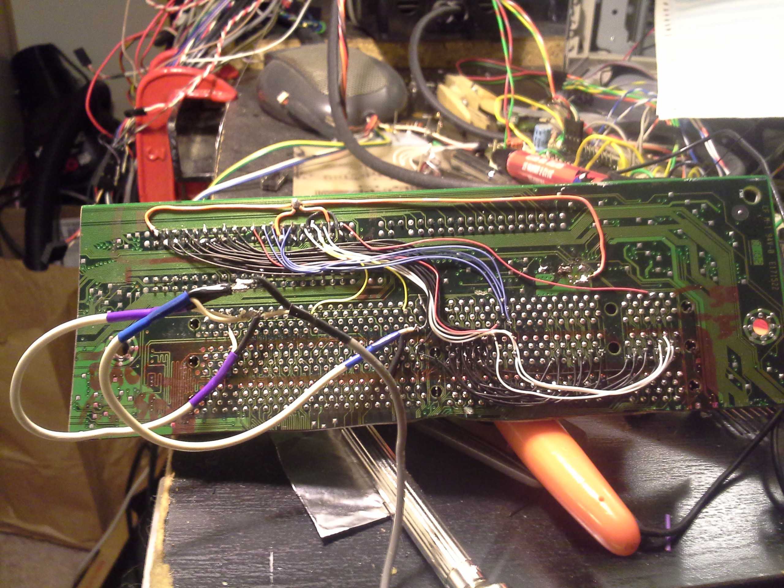
Since I had to do the rerouting of the clock-signals, I figured I'd take that picture I'd intended-to before of the back of the hack[saw]ed-motherboard...
Since this guy's Synchronous, the clock is, really, the only one that *needs* to be shielded... right? The other guys can glitch-out as much as they want (and likely will quite a bit as they all change at the same clock-edge), but as long as they've settled by the next clock-edge it should be OK... right...? Seems so. But that clock is sure sensitive. (And that description probably isn't *so* great, because coupling/crosstalk could cause spikes that exceed the input-voltage specs... This ain't a product, it's a hack. YMMV).
Anyways, after that clock was routed away from other signals (and not Y'd to the AVR), it seems to be working.
(Ah, yeah, there're a few other things that make this clock maybe more sensitive than #sdramThing4.5 "Logic Analyzer" ... 1 ) This crystal's only been verified down to 3.6V, now at 3.3V... the signal swing may be *just* at the threshold... 2) sT4.5 eventually had a clock-expander chip... This guy takes in a clock signal, then PLL-locks to it, outputting the same signal to several outputs, but regenerated... That's a handy thing).
Oh yeah, and that motherboard happened to physically tie-together /CS0 to /CS2 (and /CS1 to /CS3) which is a problem... Thankfully one of the slots had those traces on the top-side of the motherboard, and it was easy to cut them (the other two slots, not so much).
So, I replaced that wire with a shorter one that seems to be slightly more robust... and now it's darn-near stable. Made a video of the instability of the last one, but it's probably not worth uploading. Could almost chalk it up to a broken wire, like happens with headphones after alot of use. But I "beeped" it out pretty vigorously and no problems found.
And something *really* weird... (plausibly worth uploading for others' brain-pickings?)
The signal-swing at the output of my crystal-oscillator was somewhere around 0.25V! Yet the signal-swing near the input to the DIMM was nearly 3V. (Around 0.5V at the AVR).
I mean, I know there's a possibility for signal-reflection and all, did I just happen to pick the exact length that caused that to put an anti-node right at the source?! Seems crazy. What is it, 6in/ns, roughly? That was about 8-12in, nowhere near enough for even a half-period at 16MHz to be longer than one trace-length... right?
So that's a bit of a mind-boggler.
Ideas?
Discussions
Become a Hackaday.io Member
Create an account to leave a comment. Already have an account? Log In.
I'm late to this party, but I've collected a long list of ways to avoid noise issues in circuits at this page... something there might help:
http://techref.massmind.org/techref/noises.htm
Are you sure? yes | no
Great list/resources, thanks!
I dig the wire-wrapping explanations... as backwards as it sounds in this era to even refer to wire-wrapping, those techniques are great for any hand-wiring, or even PCB.
And NON-through-hole plated holes + inserting surface-mount capacitors is a great idea for future projects.
Interesting points, as well, regarding using slower logic-families, and the reference to RS-232. That's already come up in this project... I opted for the faster family, but maybe that's not the best idea. The problem came up because I had a slower family latch and a faster one running in parallel, the faster one latched earlier in the clock-signal, so they didn't play well together. Though, *intentionally* slowed-edges through series-resistances etc. would probably lend themselves better toward sticking with the slower family. Hmm...
I'll definitely be referring back to that page, and the rest of these comments, when it comes time to design a PCB.
Are you sure? yes | no
Are those cheap audio grade coax or high frequency micro coax with a much tighter tolerance for impedance? RG174 is good enough for running at these type of clock frequency.
Alternate source of small coax from computer trash: WiFi router uses 50 ohms coax, good quality thick VGA has 75 ohms.
Are you sure? yes | no
Indeed, I've used the (really thin, used in a laptop) wifi-cables in the past with great success. I didn't think about VGA, that's a great source for long-stretches... maybe a good idea to rip an old cable apart and spool up some thin coax for later projects.
As far as the wire I used originally, I think it might've been audio-grade... The one I replaced it with *feels* much higher-quality (and it's a bit shorter, as well). Maybe this one's actually braided...
And... I did end up grounding the receiving-side of the shield, as well... Seems to have helped.
I decided to use a clock-regeneration/fanout chip (CY2305, with PLL). I also tried a 74x04 inverter as a buffer. Interesting note: As I recall, before I tied the end-shields to ground, the signal measured at the regenerator still looked very small, while that at the output was nearly 6V(!) (even with the new cable). But it was working. Now I'm measuring it again, and it's not showing that problem.
The clock-regenerator has several outputs, but one has internal-feedback. Tying the SDRAM's clock-cable (even the new one) to that internal-fed-back pin caused no output from the regenerator at all, but tying it to another output (and tying my AVR's and latches' clock-inputs to that fed-back pin) worked. Now, with the shields tied-to-ground, the clock-regenerator is able to generate a decent signal, even with the SDRAM-clock tied to that fed-back pin...
Now, that gets me thinking... ( @Ted Yapo, too ) At one point I did try a series-resistance with the regenerator's non-fed-back outputs, just to see what happened. I think I grabbed 100ohms, since that was sitting at-reach... and, as I recall, the 'scope was showing nearly 0V swing on the cable-side of the resistor, but, again as I recall, the system was working. (and, again, without that resistor, and now with end-shields grounded, and driven by the regenerater, I see a pretty clean signal at the cable-entrance). So, that measurement was pretty much the same as that which led up to this post in the first place, except with the different cable and with a regenerator-chip and a series-resistance.
Now... that leads me to wonder: The original circuit was driven by the output of the Crystal-Oscillator (I also tried with a 74x04 inverter chip)... Which probably has internal-impedance, maybe something along the lines of 100ohms.
Interesting... So I don't quite grasp it, but maybe using that resistor (or the internal impedance of the XTAL/'04) is something like intentionally inserting a *voltage* antinode... Plausibly the current is forced-through(?).
Something along the lines of wabbling a hand-saw blade's handle and stabilizing the blade with your finger at different points near the handle... the end would still swing much more dramatically than the handle, trying to maintain whatever frequency you're wabbling with (trying, regardless of the actual resonant-frequency of the blade) no matter where you put your fingers (not too far away from the handle).
So, I'm not certain, but I think the end-result is that the receiving-end shields should probably be grounded, even though there's definitely a loop created between the receiving-end shield and the SDRAM's regular-ol' ground routing away from the breadboard. I think that helps to tame the "sawblade"'s wabbling too dramatically at the end. And... that antinode at the source might very well be a desirable characteristic, maybe part of the point of series-termination, just a bit backwards from what one might expect when 'scoping.
Are you sure? yes | no
The reflection ocefficient (https://en.wikipedia.org/wiki/Reflection_coefficient) can be between -1 and +1, so not likely to see the output amplitude at more than 2X the input from reflection alone.
The other possibilities is magnetic coupled crosstalk from other traces superimposed on top of the waveform. They work like a transformer.
Also the clock source (e.g. oscillator can) usually has a weak drive already and the passive scope capacitance load pushed it over the edge and loaded down the signal that you are measuring. Did you probe at the source and destination at the same time doing that measurement?
Are you sure? yes | no
Ah hah... there's a thought; capacitive-loading from the probe might be noticeable at the source, maybe more-so than at the receiver, due to transmission-lines' effectively looking like a fixed impedance to the source, regardless of the load-attached at the end of the transmission-line. Still, woulda thought that only applies to *long* (compared to wavelength) lines. but something I hadn't pondered.
Crosstalk... I can definitely see that causing the flaky-clocking issue, but I find it hard to imagine that's responsible for the 3Vp-p signal, which appeared to be pretty much a sine-wave. Though now that you mention it, I should rerun that experiment with no other signals running... it's plausible, for sure, the other signals, which only happen during a small fraction of the clock-periods (but all on the same clock-edges), might've overlapped enough on my analog-scope to *look* constant... (a bit like an eye-diagram). the *actual* clock-signal, which happens more often, but might be too weak to cause a trigger, might've been burried in the background-noise. Hmmm....
Since I'm using the old motherboard as a breakout, who knows where they routed these things. Though I'd've assumed they'd've been shielded, it was a *really* poor-quality mobo (I inherited two of these, because all the capacitors on *both* blew within the first year!). So, it's entirely likely that even though I did quite a bit to shield the thing between the crystal and the DIMM-socket, there may be crosstalk elsewhere on the motherboard (and several potential additional locations for reflection, etc.)
And... there's the quality of the wire, which I haven't inspected. As well as the fact that I didn't tie the receiving-ends of the shielding to ground... hmmm... For some reason that speaks to me of kinda like a hand-saw-blade... where you wiggle the handle just a little bit, but the end of the blade might wobble dramatically.
Good point, as well. I should measure the (unloaded) crystal output, and maybe again with a couple resistive-loads to get a sense for its drive-characteristics.
I'm tempted to resolder that blasted thing the way it was and run these experiments, now... despite the fact it's working pretty stably with the new wiring.
And, great call about measuring both the source and the receiver at the same time. That'd definitely be more informative.
Are you sure? yes | no
>which appeared to be pretty much a sine-wave
If your scope's and/or probe's bandwidth are not high enough for the harmonics, then all you can see is the fundamental frequency. i.e. a sine wave
Passive probes tend to be upper range of 100MHz or so. Some might claim to go to 150.
Are you sure? yes | no
Not sure I have the answer, but one thing I do know about the "black art" is that you can cure some ills with source-termination (inline resistors at the driver end), assuming you know the impedance of your transmission line. I'll have to go back to see if there are any of these "--/\/\/--" at the drivers in your schematics :-)
One other possibility is probing error: ground lead length on the scope probe, etc.
Are you sure? yes | no
source-resistors! BAH!
I'll save you the schematic-lookup-time... No, I didn't.
This is a hack-job on a breadboard, so they'll be easy to add! Thanks for the idea. I don't know the transmission-line impedance (I just grabbed an old shielded board-to-board cable from inside an old VCR)... It could be quite shitty (or maybe even for audio). Though, breadboarded, I can experiment a lot :)
Good call on the grounding-points... I actually tied the ground to a single point on the circuit, then measured both points using that same ground-point. And, per my "saw-blade" description to KCLee's comment, it's entirely possible the shield at the end of the transmission-line (which is not tied to ground at the receiver) is swinging dramatically as well.
What a weird concept, and makes me wonder whether tying that shield to ground at the receiver is a good idea, even neglecting my (plausibly unjust) fear of ground-loops. If it's swinging that much then what'll that do to the power supplied to the DIMM...? (Though it's probably quite weak, maybe no effect).
I wanna check this now... but dang, it's all fixed (new wire)!
Are you sure? yes | no
Mystery fixes always raise an interesting question - will you learn something valuable from sussing out the root cause, or will it just be a waste of time? I probably answer that wrong half the time.
As far as cable impedance - just use 75 ohm terminations. My guess is that line impedances you're likely to see on any common lines would be between 50 and 120. A 75-ohm source impedance would give 14 and 13 dB return loss, respectively, at those extremes, enough to knock reflections down significantly. Or use 68 - if termination is going to fix it, anything in the general range will probably do.
Are you sure? yes | no
The impedance of the wires are going to be high as they are far from a ground/power plane, so they have less capacitive and mostly inductive.
The SDRAM module signals on the other hand are designed for 50 to 60 ohms range. The clock line would be lower because you are connecting them in parallel (hence parallel impedance) instead of a zero skew drivers to each of the clock lines individually in a point to point topology.
Chips/driver impedasnces tends to be in the 30 ohms range - the stronger one have lower impedance and weaker ones higher. The IOH/IOL part of the datasheet can get you an estimate.
A source termination even if not near the transmission line would still dampen the reflections a bit by lossy dissipation.
Are you sure? yes | no
It needs not be a black art as there are math, equations and all kinds of expensive simulation tools that do a decent job of predicting what would happen if you have $ and a good enough model.
Are you sure? yes | no
I spent most of a summer doing hyperlynx simulations for gigabit [fiber] ethernet (as well as DDR)... something as simple as a mere via, or even an additional couple mm of trace-length had *tremendous* effect on the results. (imagine the effects of bumping up to a big fat surface-mount pad and then an undefined blob of solder onto a similarly-undefined chip-resistor), and trying to keep impedance-matching in all those "bumps"). Those guys, OTOH, have much stricter requirements for overshoot and whatnot, nevermind (for DDR) skew is a huge issue. The end-result, as I recall, was to place *pads* for termination resistors at both ends, and they'd determine what values (and brand/make) to use through trial/error with a high-end oscilloscope and environment-chambers. OTOH, again, this was for a project where being within specs was absolutely essential (not a consumer product).
And, I think I recall, according to the sims, the use of source and termination resistors, and choosing a proper value, usually overcame whatever oddities the vias or whatnot introduced.
Though, again, I don't recall ever seeing waveforms like what I'm seeing here, so this is definitely a weirdy for me.
Are you sure? yes | no
"I probably answer that wrong half the time."
You and me both. :)
Your method regarding what values to try seem totally legit to me...
Especially in a digital-logic sense, where the SNR is *huge*... It's not like we're trying to feed a weak aerial UHF signal down 300 feet of coax! But, again (responded to KCLee) was my experience with so many (countless, several per day for months on end) simulations which suggested the resistance-values needed to be tuned precisely...
I still call it an "art", maybe "black-art" is a bit strong. The fact Radios/TVs work at all astounds me... and they didn't even have 1% resistors for termination way back in the day.
So, you're probably onto something with the "in-range" terminators, and that may be a decent line-of-thought leading to whether it's worth it to determine the root-cause, especially seeing as how this different wire seems to have completely solved the problem (I can't even get it to fail, now).
As far as this "project" (and its instructions) goes, maybe it's worthwhile to note that: after connectors/connections being the first likely cause of failure, the second-likely cause is a shitty clock-signal, and throw some ideas as to how to resolve it (and maybe some code-snippets regarding how to test it).
As far as board-design...
I can't imagine it would be *nearly* so sensitive if even minimal considerations were taken... even if not impedance-matched, merely shielding the clock trace... (probably OK even on a 2-layer board), termination-resistors are a good idea, if nothing else throw a piece of wire across the pads for the lazy ;) And, at that point, there'd be a more reliable source of crystals actually rated for 3.3V and maybe even with decent drive-strengths...
But it's still weird (to me) what I saw!
Are you sure? yes | no
I'll second the resistor idea. I've seen that make a HUGE difference. Basically it makes the signal rise and fall a tad slower and thereby avoids all sort of ringing, cross talk, and other high frequency issues.
The RS232 spec specifically limits rise and fall time for that reason... and you can run pretty solid baud rates over amazingly long distances without shielding as a result... if it's real RS232.
Are you sure? yes | no
"If it's real RS232" Hah! Does that exist anymore? As I recall, my PL2303 claims to handle baud-rates around 1Mbps, WAY outside the RS-232 slew-rate specs ;) Interesting point, though, about the long-distances sans shielding... I recall old school-buildings wired for dumb-terminals that had unshielded cables running from one end of the building to the other.
Some interesting ponderances, though... We all seem to have different ways of looking at the same problem (especially WRT series-termination)... We've got @K.C. Lee who's been talking about reflection (and coefficients/math) quite a bit... We've got @Ted Yapo talking about throwing in an educated-guess/good-'nough value series-terminator to "cure ills.".. And there's you talking about intentionally slowing the slew-rates for various purposes, but especially relating to cross-talk/ringing. And me trying to compare the damned thing to wabbling saw-blades.
Are you sure? yes | no
Yup, it's a hack.
Are you sure? yes | no
haha, despite this being HaD, I don't know whether to be proud of that or not ;)
Are you sure? yes | no
if you're not proud of it, why do you even share it here ? ;-)
Are you sure? yes | no
Nothing is as good as a clever hack.
Are you sure? yes | no
haha, good call... I'll have to think about that one ;)
Are you sure? yes | no