 Eric Hertz
You may have noticed in previous logs, I might've gone a bit overboard in using resistors to route signals where, in a logic/gate-sense, the, maybe, more "proper" way to do these things is with e.g. bidirectional-latches (newly-discovered, to me, 74x543) or a one-directional latch (e.g. 74x574/374) and a buffer (e.g. 74x244), both with output-enables.
I'm well-aware of the "more-proper" logic/gate-sense. My first large-scale TTL circuit, an LCD-controller, was based on such logic, self-taught, during summer vacation in highschool... shit was that nearly 20 years ago now? 15, fhwew!
That guy...


...well, all its timing (pixel-clock, porches, addressing of the SRAM) was handled via 74-series chips. The microcontroller just loaded the SRAM with updated-pixel information, but otherwise sat unused. (Never occured to me, until just now, I could've quite-literally, removed the uC and still held a stable image on-screen, refreshing at 60Hz, much as how #sdramThing4.5 "Logic Analyzer" can have its uC removed and still perform sample/repeat. I'll never stop thanking @frankstripod for convincing me to create that (really long) video showing sT4.5 running while I quite-literally pull the microcontroller from its socket). BUT, the point is, in order to *write* data into that SRAM *while* the SRAM is also being used for refreshing the display, you have to reroute data, in and out, with the right timing...
-----------
Anyhow, I'm well-aware of the, maybe, "more-proper" methods of using latches and buffers with output-enables. But, again, doing-so requires quite a bit of logic, as well as quite a few *additional* control-signals.
E.G. say you want to use a buffer for one direction and a latch for the other, you need, at the very least, two output-enable signals.
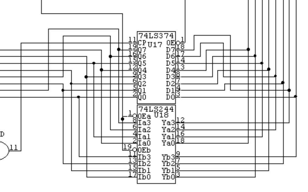
(from the ol' LCD-controller)
So, if everything's *easy-peasy* you could merely throw an inverter between those output-enables, and call it good. (or maybe call it "direction"). But what when you have that same "bus" connected to *several* such bidirectional "sources" (such as, in this project, the "Side-Kick's" I/O's, which are used for sampling 32-bits of data, then the processor/host can read that data back via an 8-bit bus)...? Now you need an output-enable for each set of 8-bits (4!). and a direction signal, as well.
That's a lot of signals!
---------
I've gone into that specific case in a previous log, so won't repeat it here. But, I'm working on a new thing for this project...
Wouldn't it be nice to have the option to sample 8bits with four-times as many samples...? (Remember, with this system, we can sample 32-bits simultaneously, and throwing another DIMM at the equation could easily bump that up to 96 bits!).
So, I thought I'd look into presettable-shift-registers. The idea being:
Each "byte" of the "Side-Kick" (sample-memory) can be selected with the DQM ("data mask") input... Kinda like an output-enable on a latch.
So, say, the "Free-Runner" loops through the entire memory-space 4 times, instead of once,.. Somehow we need to select which *byte* of sample-memory we want to sample into. So, iterate through those DQM's, one at a time. DQM is active-high, but that means we want to "mask" (in the "normal" sense of *hiding*, rather than the oft-used programmatic sense of *enabling*) all the bytes we *don't* want written...
So, to write/sample the first byte (of the four parallel bytes), we need to load 0b1110 to the DQM inputs. To write the second byte we need to load 0b1101, the third 0b1011, then 0b0111.
Well, dagnabbit, that looks a heck of a lot like the doings of a shift-register.
OK, but I ALSO want to have the OPTION to sample 32 bits simultaneously (with 1/4 as many stored-samples)...
So, this is where I come up with the idea I need some sort of serial-in, parallel-out shift-register where I can *pre-set* it with a value such as 0b0000, should I want to sample 32 bits simultaneously, or *pre-set* it with a value such as 0b1110, should I want to sample 8 bits into the first byte through the first *loop*, then 8 bits into the second byte through the second *loop*, etc.
There was a time, yahknow, where one could dig out the ol' 74-series reference-manual and most-likely, with enough index-browsing, come up with darn-near exactly the chip needed. Apparently those days are no longer here. There are *a ton* of 74-families, these days, BUT, most of the newer families seem to only actually have *a select few* of the original selection...
So, I came across this page... which is basically describing exactly what I'm looking for... Except... My Usual Supplier doesn't supply the chip mentioned (74x395), especially in the high-speed variety I'd like, for this project.
So, let's step back for a second... That Page shows the "maybe more proper" method of creating such a device (a parallel-load, serial-in, parallel-out shift-register).
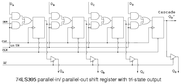
Perty slick, really... and if it existed, and was easily-available, it'd be my go-to for this purpose. But... it's apparently not.
So, let's take a step back for a second... What does this thing *really* do...? All those logic gates basically allow for routing the data-flow depending on whether you want to parallel-load the shift-register (basically, with an initial value), or whether you want to shift-in serial-data and have that serial-data output on the pins.
Actually, that circuit, right there, is dang-near exactly the "maybe more proper" circuit for my needs... But I really don't feel like investing in a bunch of AND gates or OR gates, and there's several inverters involved, as well... And @James Newton, you know I don't want to use an FPGA... ;)
-------------
So, check this out...
Back to the same idea used for whittling 32 parallel bidirectional bits down to 8, using nothing more than latches and resistors...
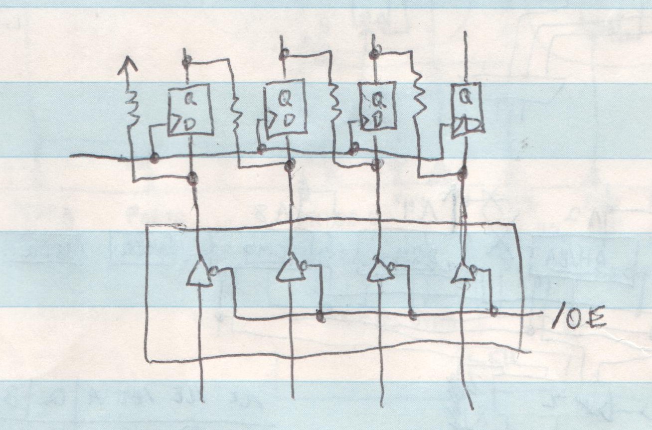
What we really want is the option to *load* those D-Q latches with an intial-value *in parallel*, like a regular-ol' D-Q latch, like the '574 I've already invested heavily in (or the '374/'373 you can find all over old circuit boards). Then turn the damned thing into a shift-register, such that every-clock-pulse causes whatever was *initially loaded* to *shift* one bit to the right.
So, now... What've we accomplished...?
The drawing shows a buffer at the bottom, but it could just as easily be a latch, as long as it has an /OE input, just like the ol' trusty '574...
Switch that /OE High when shifting... and... we've dun reduced Two ANDs, An Inverter, and An OR to nothing more than A Resistor. (PER BIT... For the four-bits necessary here, we've reduced 20 16 (MATH-FAIL) gates down to 4 resistors!)
-----------------
I propose, at this moment, as something I hadn't pondered before, that there might in fact come a point where, plausibly, 5 gates might in fact take more power than the necessary resistor, even if that resistor does nothing but create heat.
I propose, further, that the number of gates/latches necessary for all those extra control-signals (and the software to control them) might, as well, add to the power-factor which might, at some point, plausibly rare, be offset by little more than a single resistor.
</green-moment>
------------
Anyways, in the interest of designing this circuit... It means that I can use my trusty (and largely-invested-in) '574s and resistor-networks for this entirely new purpose, as well. Wee!
So, I hereby dub this: Resistor-Latch-Logic, or maybe Latch-Resistor-Logic. And, maybe, won't even bother investing in buffers. (Consider this my copyright, my patent-pending).
But I'll definitely be investing in more beer before closing-time.
Discussions
Become a Hackaday.io Member
Create an account to leave a comment. Already have an account? Log In.
Pondering 16-bits at 2x the number of samples... Originally thought of whether I needed to shift everything twice... but, instead, what about initializing the shift-registers with 0b1010, then allowing it to shift once to 0b0101. Dun!
Are you sure? yes | no