 ken.do
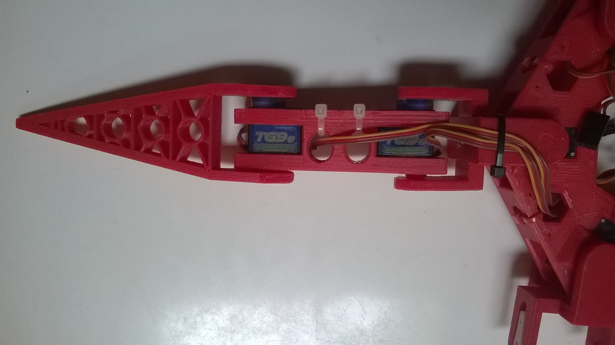
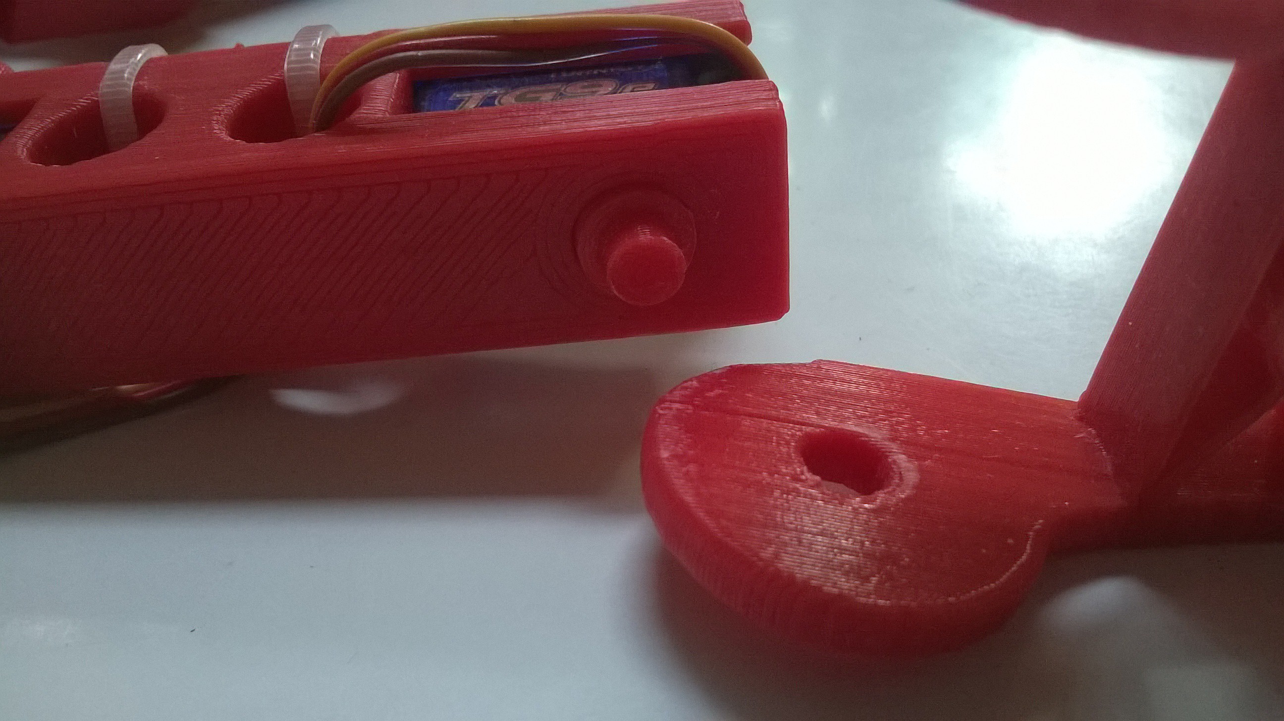
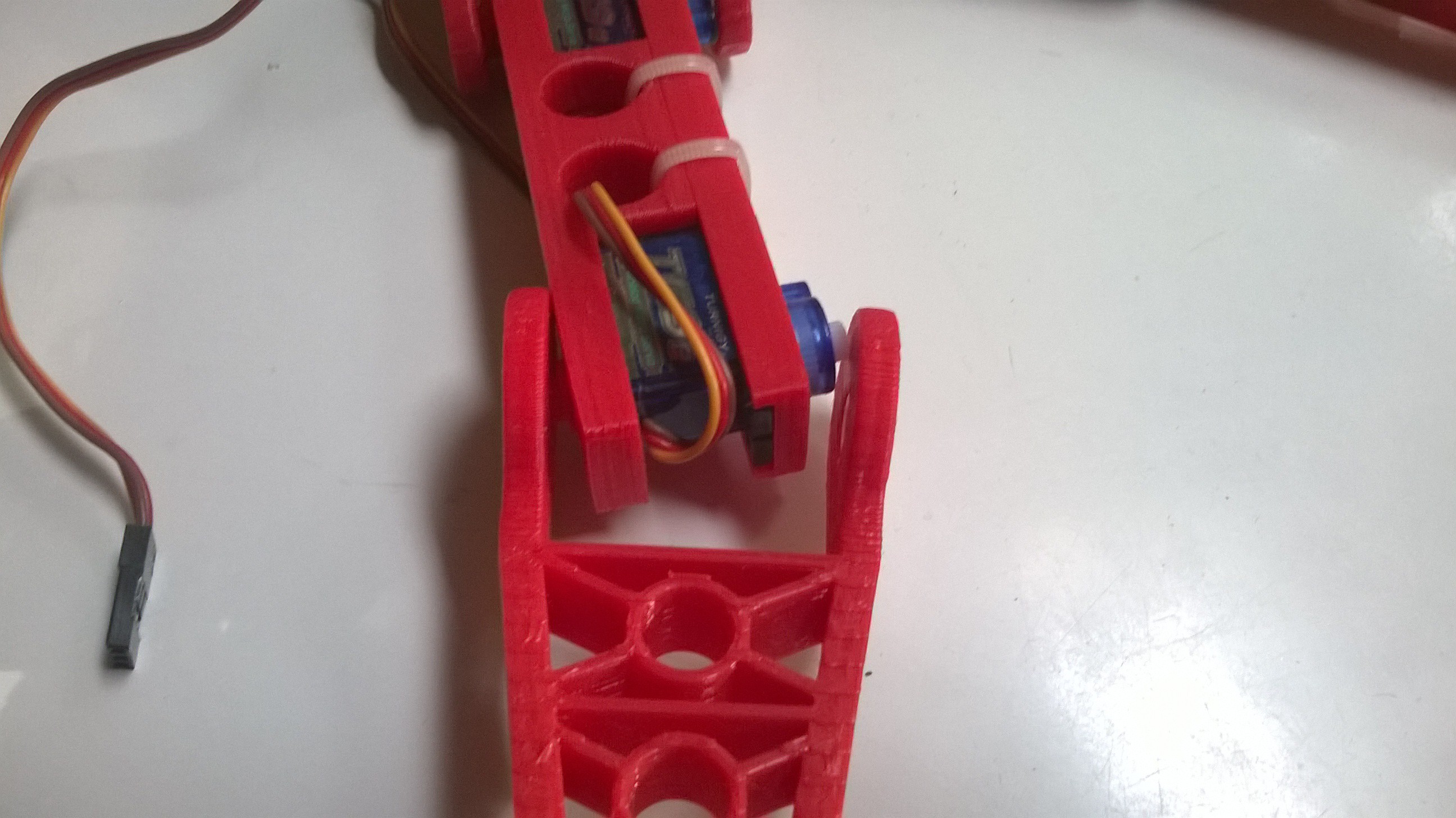
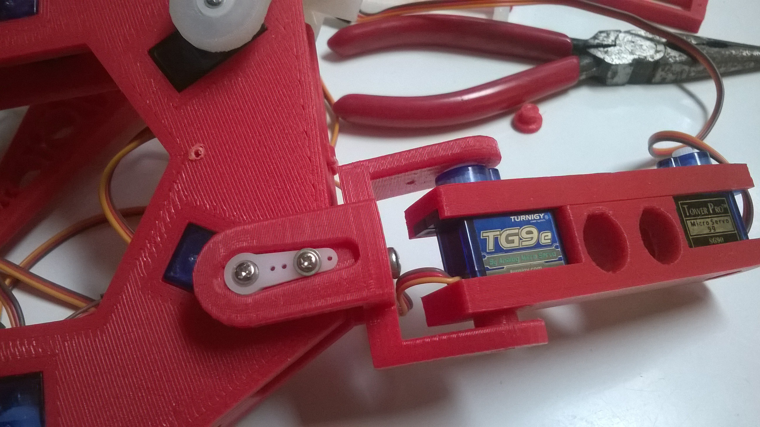
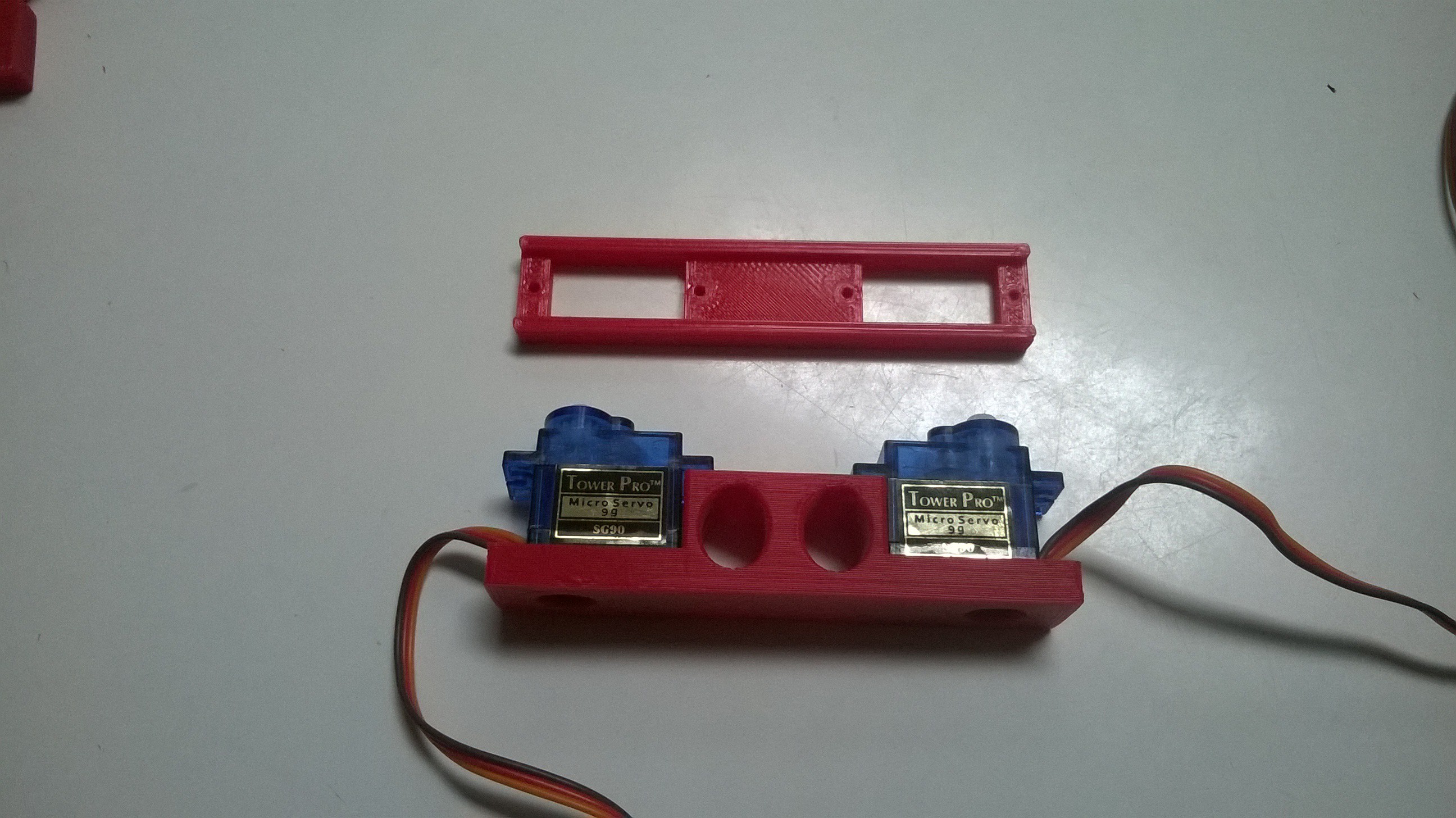
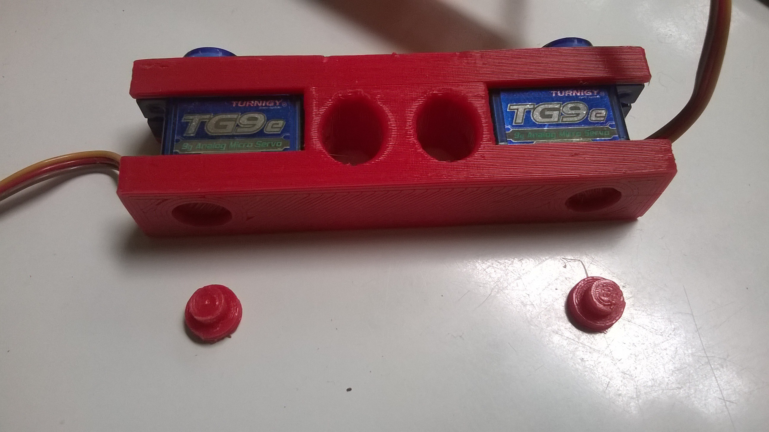
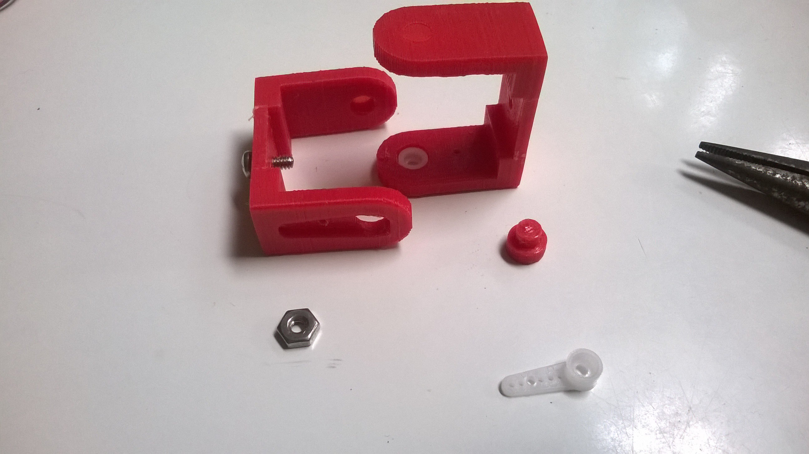
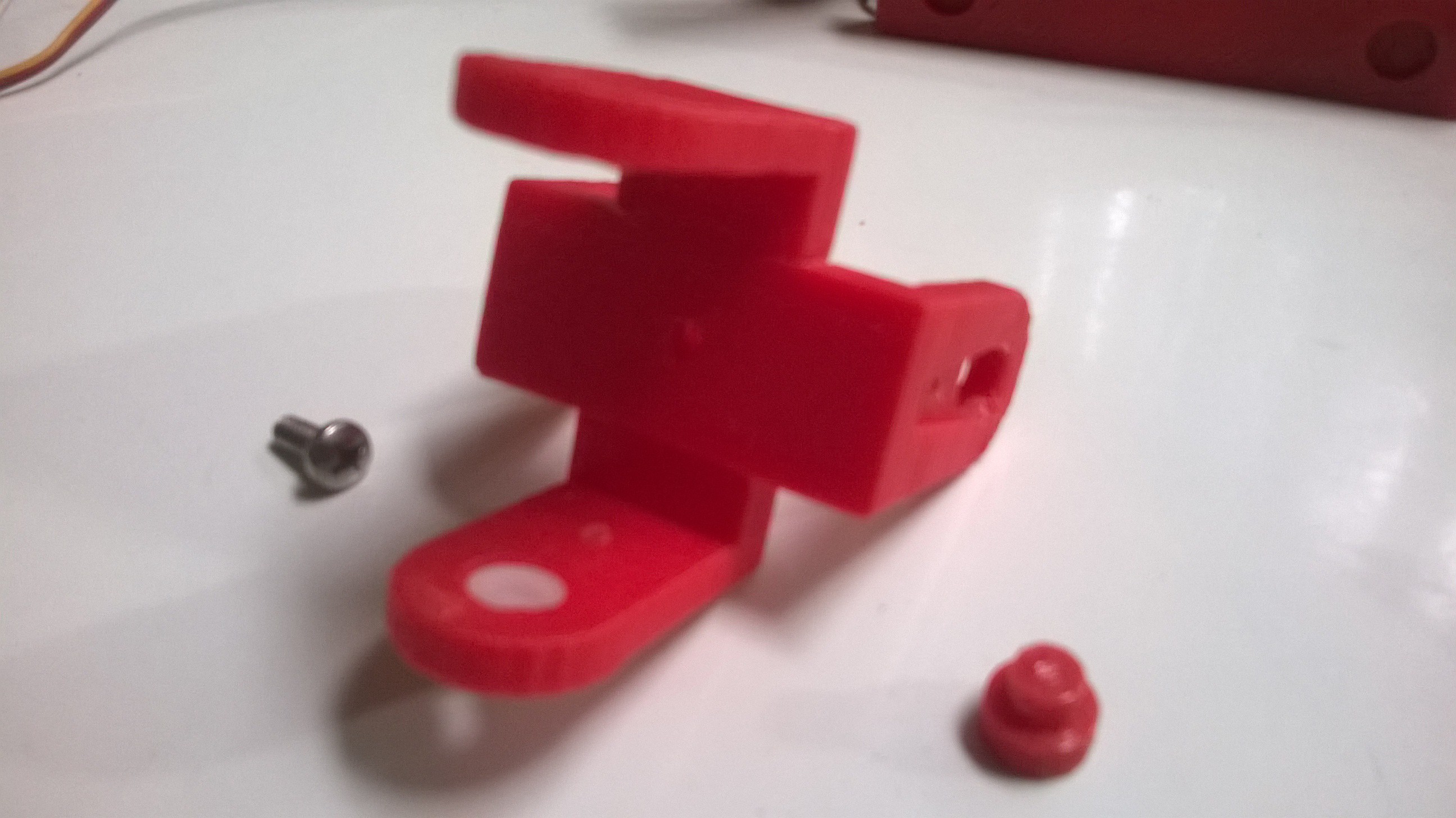
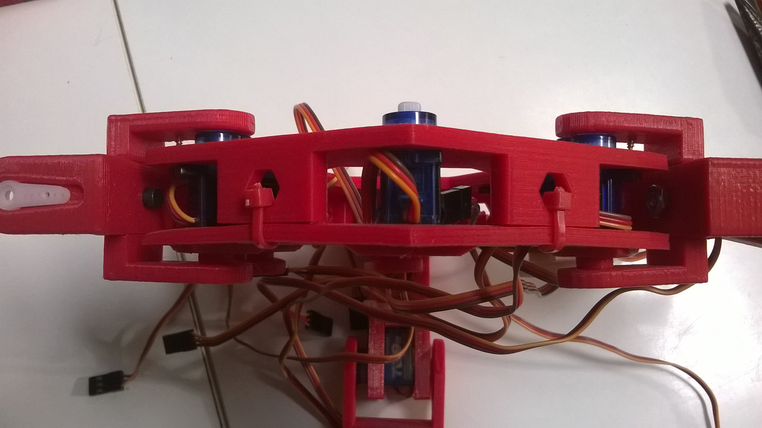
This 3D-printed hexapod robotic platform frame was designed and built from the ground up. It measures about 20" (50 cm) from leg tip to leg tip. Designed around the nylon gear sg90 servo form and re-designed around the mg90 (metal gears), it is ready for servos, a servo control board, power supply and supporting software/controllers. Use the built-in hardware assembly options (screws) or opt for a 90% zip-tie build!
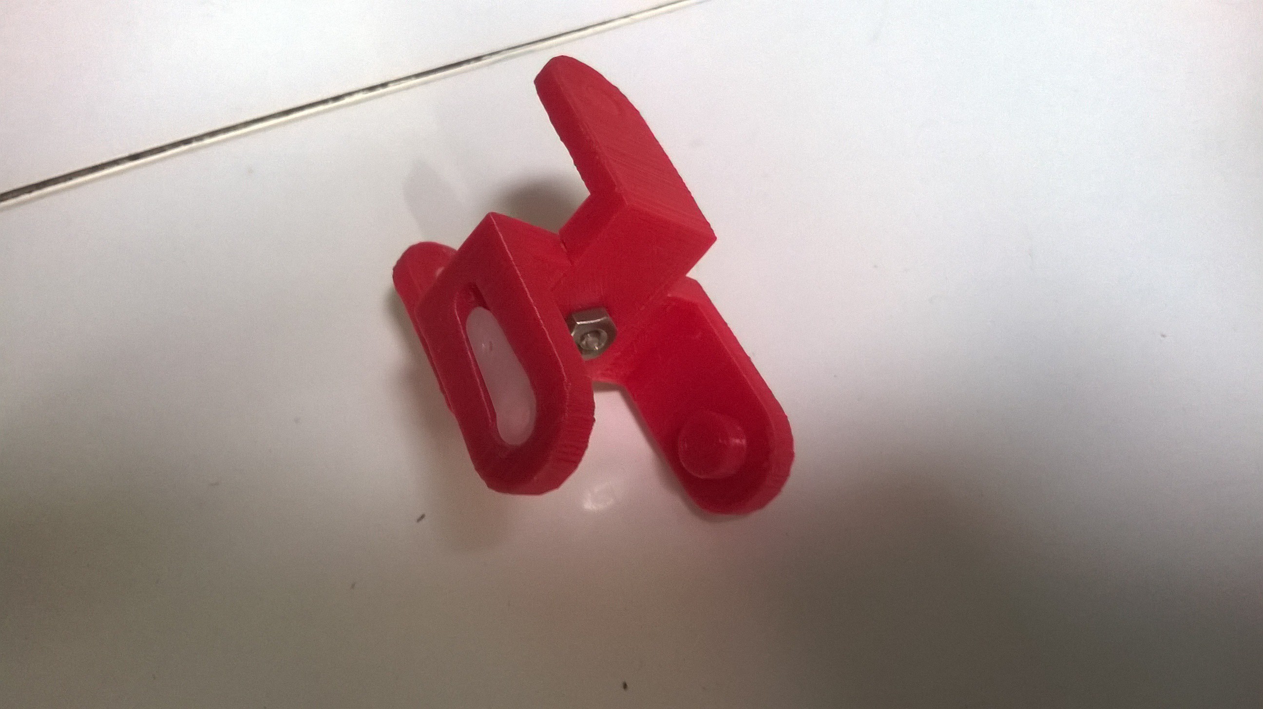
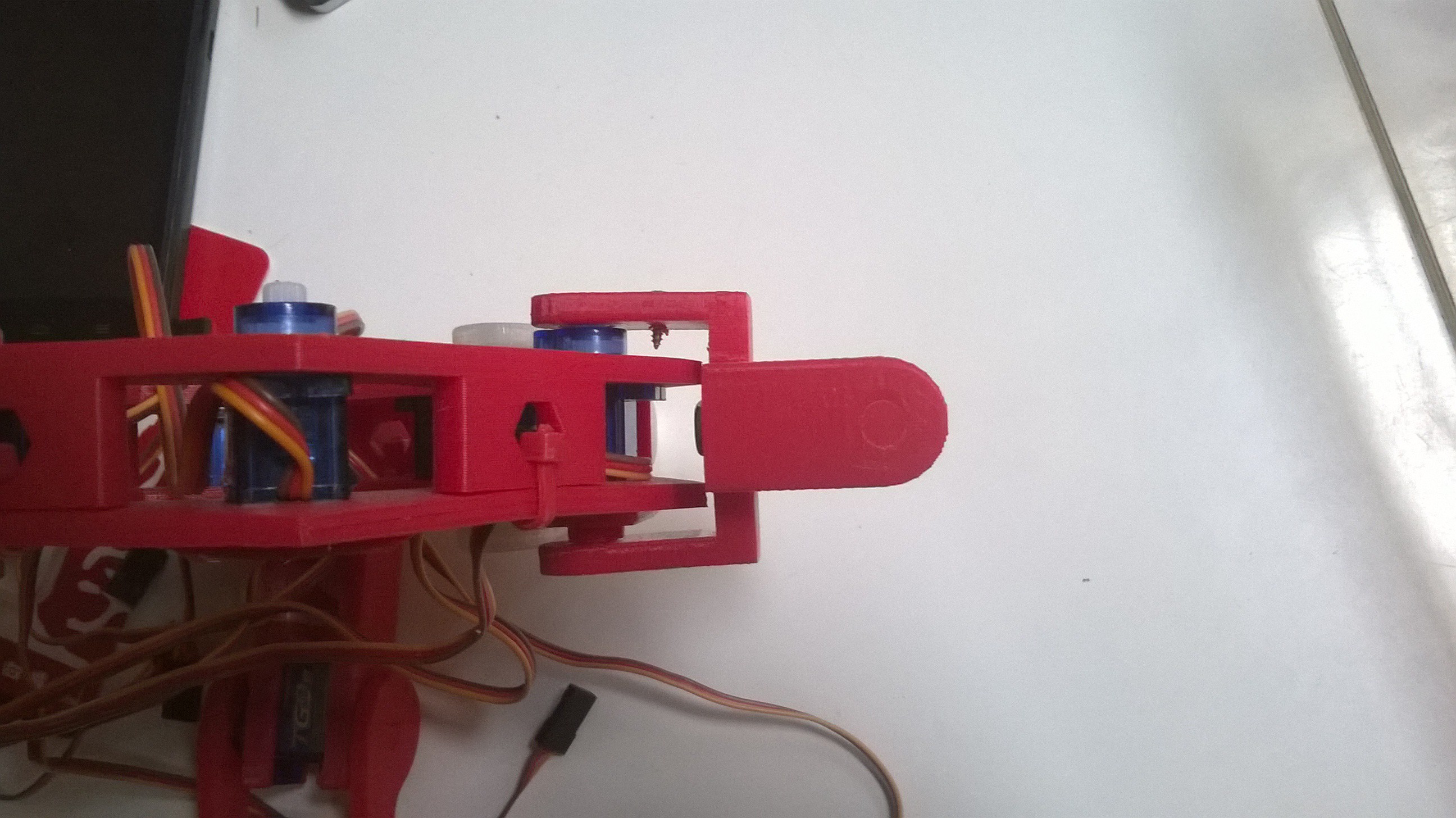
Intended to operate as both a typical 18 degrees of freedom hexapod with omnidirectional motion capabilities, it also has a 'high-floatation' mode with 12 degrees of freedom. The larger surface area is provided by the end segment of the leg laying flat on a surface like snowshoes or flippers.
This frame and motors kit is available on my Tindie page - http://bit.ly/hex_Ken_do


 Rue Mohr
 KTD-prototype
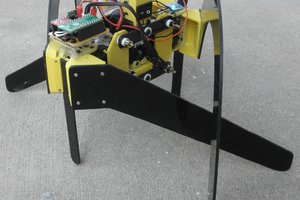
 Gertlex
 JackRC
Great design, did you manage to control it already?