 Alexandre LE GALL
This project :
I was looking for a project idea to submit for the 2018 Hackaday Prize and when I saw the "Pickle Rick Achievement", I said to myself "I want it". That's how I got the idea of my potato robot.
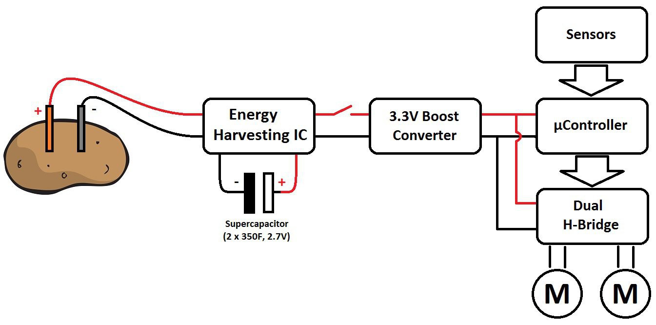
My robot is currently composed of a potato battery (energy generation), two supercapacitors (energy storage), an energy harvesting module (to extract energy from the potato to supercapacitors and generate a 3V3 power supply), an I2C motor driver (to control (with PID) and monitor the two small dc motor without overloading the main µC) and an arduino nano (the brain).
Both modules can be used for anything and everything (solar energy harvester to a lipo battery, a stepper moter driver...). The potato battery is only the fun part of this project !
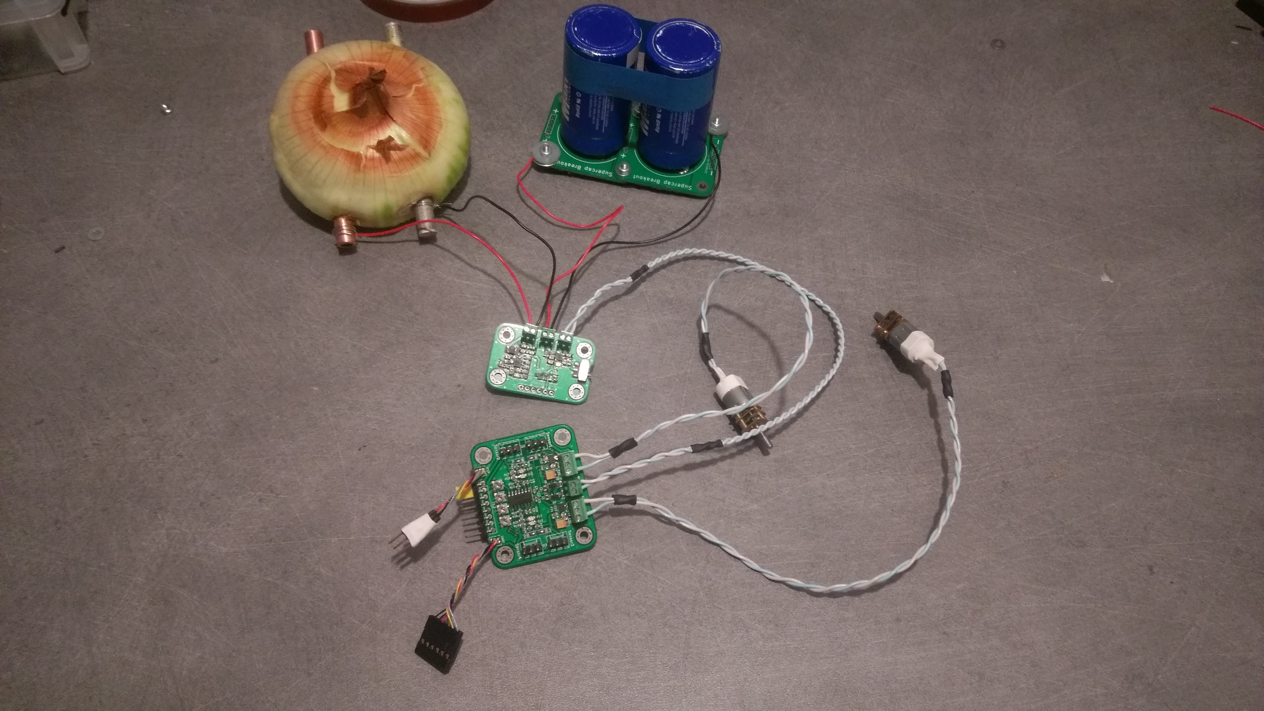
I did not have a potato when I took this picture, so I used an onion instead.
The potato battery :
A potato battery is basically a galvanic cell (or voltaic cell). It is an electrochimical cell that uses a chimical reaction (oxidation and reduction) to produce power. The metal from the two electrodes reacts with the electrolyte (the potato) and generates a flow of electrons ( = current ). The energy comes from the oxidation of the magnesium electrode, not the potato itself.
The voltage of the cell is determined by the "standard potential" of the two electrodes.
For my potato battery, i will use Magnesium for the anode (-) and Copper for the cathode (+).
The magnesium has an standard potential of -2.37V, and the copper has a standard potential of +0.38V. In theory, i should have 2.75V ( 0.38 - ( -2.37) ) but because of some electrochimcal stuff i don't completely understand, i only have around 1.6V.
If i want to increase the voltage of my potato battery, i have two options :
- Use a different metal for both electrodes (but it will be too expensive or too dangerous)
- Place multiples potato cell in series.
If i want to increase the current of my potato battery, i have three options :
- Increase the surface of the electrodes. The more surface you have, the more reaction there is and the more current is produced.
- Lower the pH of your electrolyte = use something more acidic than a potato (lemon for example)
- Reduce the internal resistance of the potato by placing the electrodes as close as possible. You can also boil the potato for a few minutes (you do not want mashed potatoes ...)
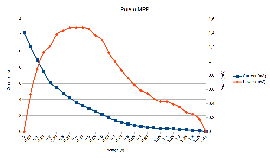
I measured the current and voltage of the potato battery to determine the maximum power (MPP) I could get. For the electrodes, i used a 8mm x 100mm magnesium rod and a 8 x 100mm copper pipe. Both electrodes were spaced 10mm apart :
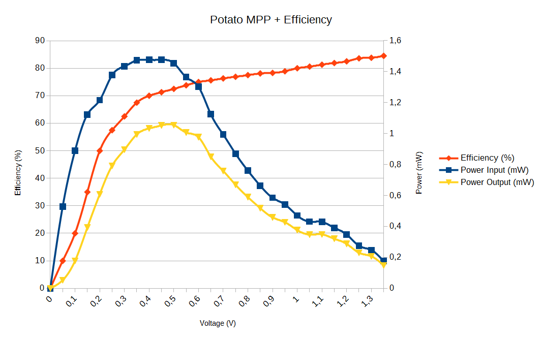
I also took into account the efficiency of the energy harvester :
I observed an open circuit voltage of 1.45V and an short circuit current of 12.31mA.
The maximum power of THIS potato battery is 1mW (MPP = 35% of Voc).
The Supercapacitors :
The two supercapacitors of 350F and 2.7V are assembled in series. This equates to having a single supercapacitor of 175F and 5.4V.
The energy of a capacitor can be calculated with the formula : E = 1/2*C* V².
If i charge my supercacitors at 5V (I saw what happens if you overload a basic electrochemical capacitor, I really do not want to see what happens to a supercapacitor in this case...), the energy of the capacitors is : E = 1/2 * 175 * 5² = 2187,5 Joules.
Because of the ernergy harvester IC and the 3V3 regulator, i can't descharge my capacitors over 2.2V. The capacitors energy that i can not use is : E = 1/2 * 175 * 2.2² = 423,5 Joules.
In total, i can use 2187.5 - 423.5 = 1764 Joules (or 0.49Wh).
If i charge both capacitors with a power of 1mW (one pair of electrodes in a small potato) , it will theoretically take 490hours to fully charge (or about 20 day...). With 4mW, it will take "only" 5 days.
At 3.3V, my two motors use each 25mA (light load). (3.3V * 25mA = 82.5 mW)
The electronics (µC, sensors... ) sould use maximum 50mA (arbitrary value). (3.3V * 50mA = 165mW)
In total, i need 0.33W. (2 * 82.5mW + 165mW = 330mW)
With 75% efficency buck/boost converter, i should use 0.44W of power from the capacitors.
With a consumption of 0.44W and a capacity of 0.49 Wh, i can power the robot for 1.11 hours (66 minutes, 49 seconds).
The energy harvester :
The heart of the energy harvesting is the BQ25504 IC from Texas Instrument (http://www.ti.com/product/BQ25504).
It is an ultra low power boost converter with battery management. The boost converter can be started with VIN as low as 330 mV, and once started, can continue to harvest energy down to VIN = 80 mV.
You can use this boost converter/charger to extract power from thermoelectric generators (TEGs), small solar panels, or electrochimical cell (like my potato battery) and store it in rechargeable Li-ion batteries, Supercapacitors, or conventional capacitors.
The BQ25504 offers battery management functions (programmable overvoltage and undervoltage protection, good battery indicator) and a programmable maximum power point tracker.
To convert the changing voltage of supercapacitors into a continuous 3V3, there is a high efficiency buck / boost converter: the TPS63030 from (http://www.ti.com/product/TPS63030)
And finally, there is also a 1.0V precision voltage reference : the ADR510 from Analog Devices (http://www.analog.com/en/products/analog-functions/voltage-references/shunt-voltage-references/adr510.html).
The I2C motor driver :
This motor driver is designed to simplify the control and the monitoring of two "small" DC electric motors. You just have to send a speed command or request power consumption via the I2C protocol, and that's it. The motor driver will do the boring calculations (PID for example) for you.
There are two DRV8839 from Texas Instruments (again)(http://www.ti.com/product/DRV8839).
It's a 1.8A dual half-bridge driver. With it, you can drive 2 dc motor in one direction, or one dc potor in both direction (you can also use it as two three-state switchs if you want)... and there are two of them on the i2c motor driver.
For speed control, there is enough to put 4 analog sensor (with a LM339 comparator to turn them into digital). You can select (with solder jumpers) if you want to measure the analog voltage or the digital signal.
Personally I use linear hall effect sensors with magnets on the wheels, but you can use any other type of sensor (photodiodes ?).
The i2c interface and calculations are done through an atmega168PB. It is therefore Arduino compatible and easy to program.