Close
0%
0%

6 inch Pi E-ink display

Make a board to interface the Raspberry Pi with a surplus Kindle screen. The smaller and cheaper, the better

Similar projects worth following
Make a custom board to interface the Raspberry Pi with a surplus Kindle screen. That's the hard part. After that is done, put the screen and Pi into a case with batteries, keyboard, and a solar panel. Ultimate goal is to have a laptop that can run for days on a single solar charge.

Power consumption for computing is a barrier that needs to be overcome as we start powering everything from renewable resources. Processor designs have advanced to the point where performance per watt is growing with each generation. Something that has stayed the same is the display. Even LED displays use about as much power as their LCD counterparts, and these are considered low compared to CRTs. An e-ink display would be the perfect solution for many applications, and only needs power to refresh the image. This could bring solar powered laptops to all corners of the globe!! In a post-apocalyptic scenario, it could be the only way you can program your Arduino ever again!

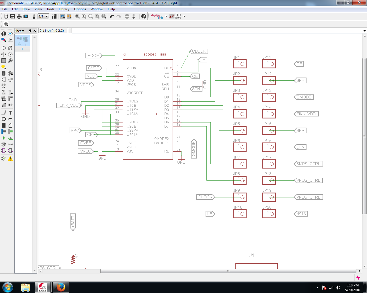
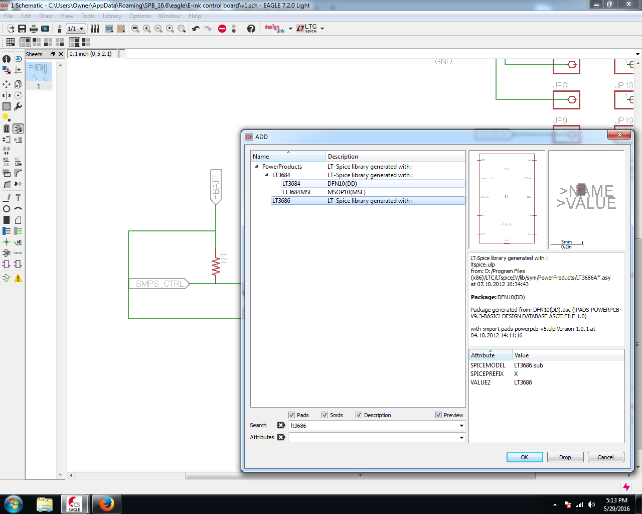
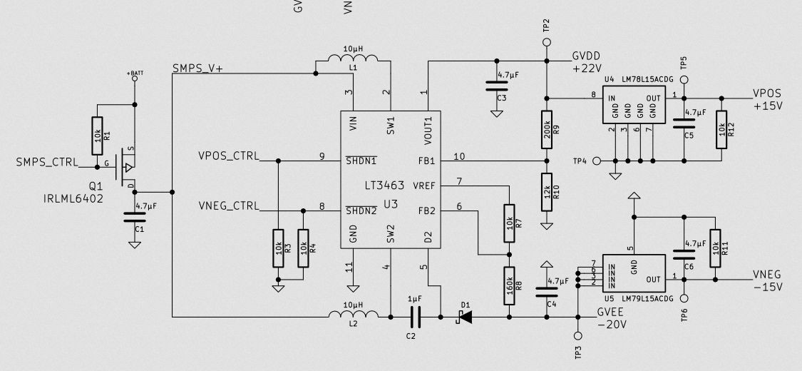
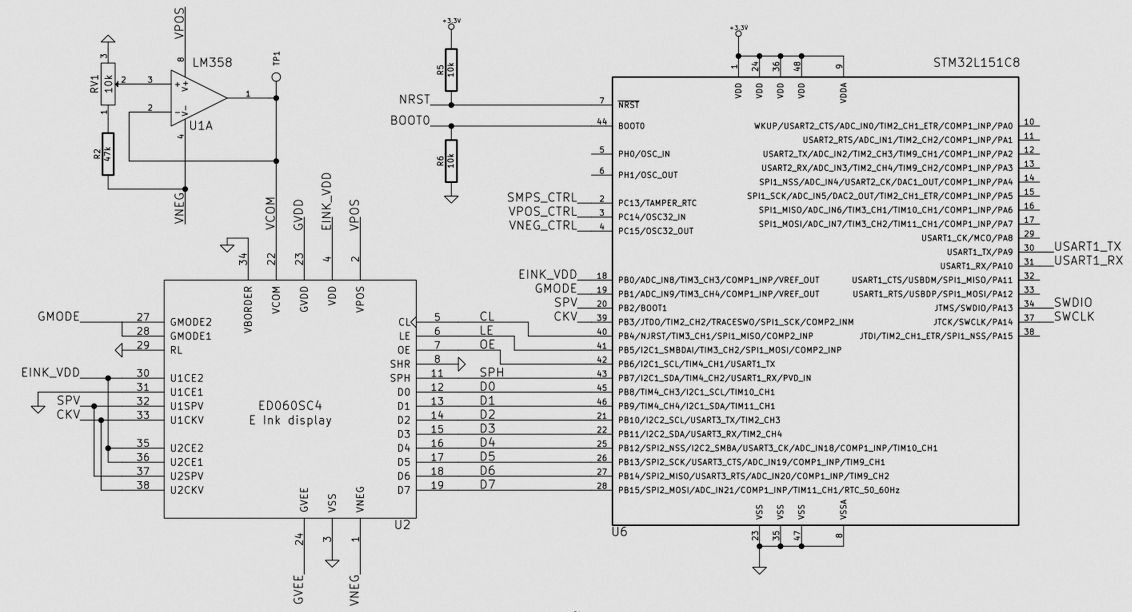
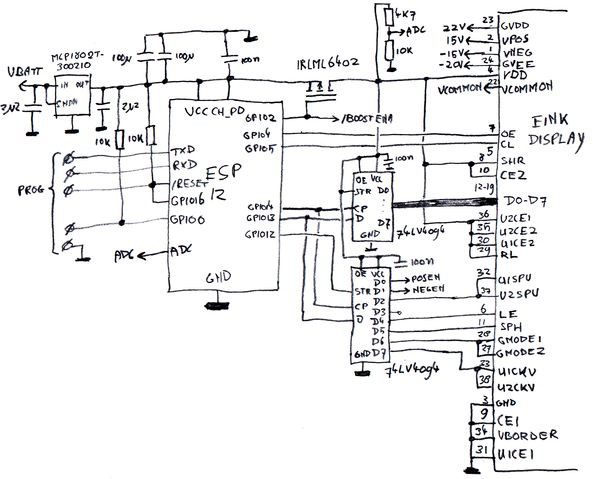
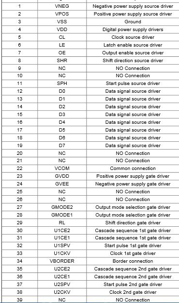
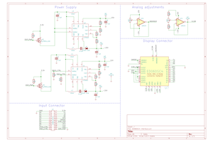
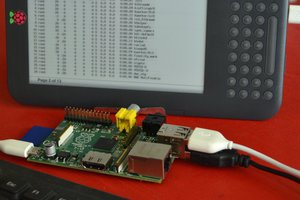
Similar to the Kindleberry Pi hacks that used a Kindle as a display for the Pi, I want to make a display for the Pi from the ever-ubiquitous ED060SC4 or similar. Here's the best work I have found on reverse engineering the protocols for the display:

http://spritesmods.com/?art=einkdisplay

http://essentialscrap.com/eink/index.html

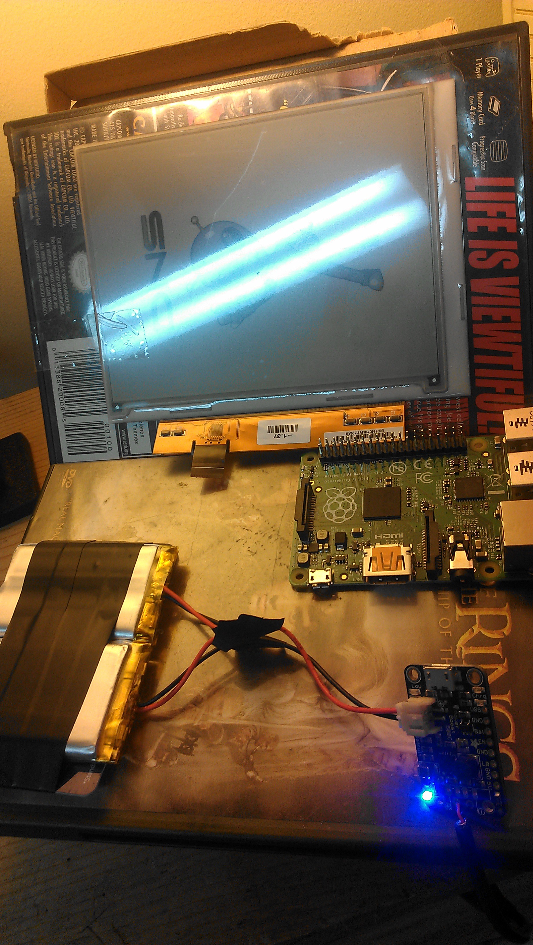
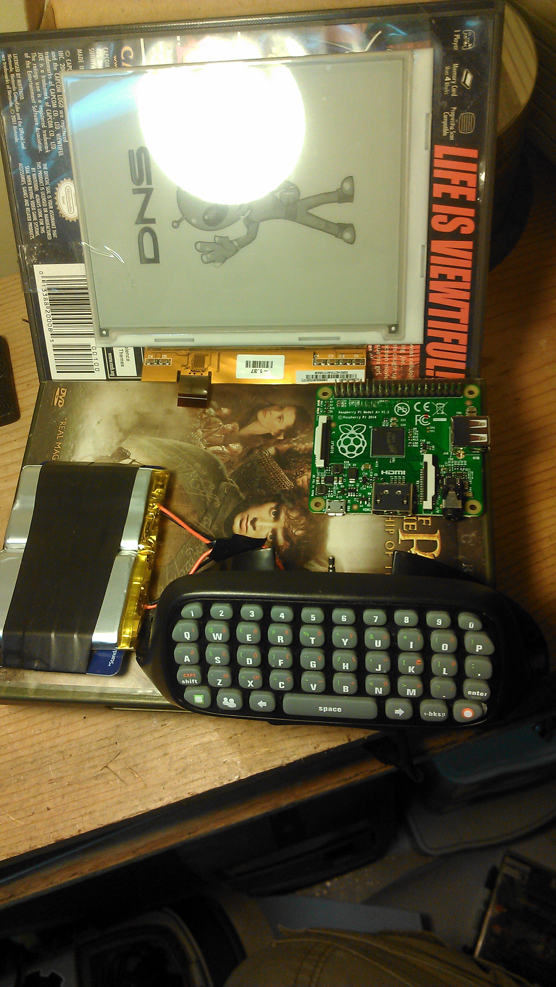
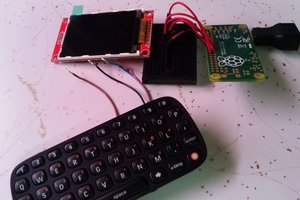
I'm going use this display with a Raspberry Pi, a case, Xbox 360 chatpad, batteries, and solar panels to make a laptop that uses as little power as possible for the post-apocalyptic world.

eink_example.sch

Example schematic

sch - 26.59 kB - 09/12/2016 at 10:58

Download

  • 5 × SMD/SMT 1206 4.7uF Capacitor
  • 1 × SMD/SMT 0603 1uF Capacitor
  • 1 × TVS Diode Arrays 1CH 36V 2000W BI Diode
  • 1 × SMD .1W 200Kohm 1% Resistor
  • 1 × INDCTR LW RDC WND 0805 10uH inductor

View all 15 components

  • Progress

    j0z0r pwn4tr0n03/17/2017 at 15:18 0 comments

    So I suck at EagleCAD, lol. I made two different revisions of boards and they both had errors that made them unusable. I couldn't even hack them into a working condition. Plus I know there will be plenty of other problems and don't want to go down the route of second guessing myself the whole time on whether the board is actually doing what it's supposed to.

    I kind of left this project for a while to go do simpler things in Eagle and maybe up my skills before trying again. I have made a few simple things, but I'm still not at the skill level I need to be. However, @sapir has a somewhat similar project: https://hackaday.io/project/7443-e-ink-display-adapter. I ordered one of his boards, as it's essentially a breakout board, and it just came in today:

    I have some parts on order from Mouser to solder on. This weekend I'm going to work on getting the code to compile on the Pi. I'm going to update to the Pi Zero, but still debating on using the original or a W. The built-in wireless might be something not everyone wants, so we shall see. Either way, the code will be the same

  • Current progress

    j0z0r pwn4tr0n05/29/2016 at 22:22 0 comments

    I already have all of the components ordered, the only thing holding me back is designing the PCB.

    I have the schematic (mostly) made in Eagle, but the board layout is where I'm having trouble. Also I ordered a bunch of different sized components which was a major mistake on my part. I have to keep referencing the packing list when placing the parts on the schematic to make sure I get the right footprint. And a few of the parts I'm using aren't available in any Eagle library I could find. I did find the connector for the display, without which this wouldn't have been possible. I know you can make a part, and it seems relatively straightforward enough, I just don't trust my limited skills with this software.

    The LM78L15ACMX isn't available, so I'm using this similar part for the footprint. The only thing I'm worried about is that it may not be numbered the same and I might be routing all these pads wrong. Either way, it's a learning experience, and I have plenty of time before the deadline to get something up and running. I'm going to do some work on it today and try to get the schematic and board finished. After perusing it to make sure all my connections are correct and all my parts are in the proper footprint, I'll send it off to OSH Park to be fabbed and cross my fingers.

  • Use cases

    j0z0r pwn4tr0n05/28/2016 at 22:05 1 comment

    The biggest reason for making this, for me, is that it would be a great modular approach to problem I face a lot. I want/need a display in my project, but I don't want to eat up precious battery life using an LCD. Something that just turns on to update would be invaluable as an internet appliance, such as a grocery list that you can update with your smartphone when you notice something you need. Conversely, using this type of display with a desktop GUI like in the Pi would yield some savings of electricity. If you were just reading text, perusing datasheets, or typing notes, screen updates wouldn't have to be that frequent, saving energy on the display budget. Also if just a small area of the screen is changing, this part can be re-written only, requiring only a portion of the energy required to change the image on the whole display.

    My ideal vision for this project involves the e-ink screen, a battery (maybe start around 2500maH and see what that does for me), small keyboard (prolly about 80% size, but otherwise a real keyboard), USB broken out for connecting a mouse and/or wi-fi, speakers of some kind (although maybe just leave the headphone port broken out too, Idk yet), solar panel on the backside of the screen so you can run it off solar power in the coming post-apocalyptic wasteland. Back of the napkin calculations say that the Pi Zero or A consume about 80maH when idle. The e-ink power driver board consumes about 50mah in standby and 100maH when updating the screen. I'd say it would be safe to say 180maH should be about average for this thing. That means a 2500maH battery should last about 12 hours, accounting for losses in conversion and that it will be making 5 volts out of a 3.7-4.2 volt battery. The solar panel I'm eyeing (as much for the output as the size) puts out about 330maH, so this would be perfect. Get about an hour of solar charge and run the device for more than an hour and a half. This is the solar panel I'm thinking about using:

    https://www.adafruit.com/products/200

    Who would use this thing? And how? For me, the laptop version would be great for camping, as I do a bit of writing on the computer, and it would a great low-cost typewriter. I already take my stock kindle camping with me because I have a library of almost a thousand books in seven ounces. Now that the full Arduino IDE is supported, you could also program an Arduino with it. I could do this while going out and standing in lines to pay bills and such, and get at least some work down instead of playing Sky Force on my phone. It would be great for taking notes in university, and with Open Office you could save it in formats recognizable by your phone or your other computers. It would be a great media player, although just for mp3s, I don't know how movies would fair. The modular aspect of it means that you would be able to write custom software to display whatever you wish, like a calendar, a webpage, or information from sensors to make a good sunlight-readable display. What would you use one for?

  • The others

    j0z0r pwn4tr0n05/28/2016 at 21:14 0 comments

    Looking through Hackaday.io, I found more than a few projects using e-ink displays. The work of these people may help get me closer to doing what I'm working with, but none of them are exactly suited for my use case for one reason or another.

    https://hackaday.io/project/7443-e-ink-display-adapter

    This one is the closest to what I need, and may even be able to be adapted to work, however, I would like to make mine smaller and Raspberry Pi specific. With this you could connect the Pi through a breadboard, but i want my solution to "bolt right up" so to speak.

    https://hackaday.io/project/11256-scott-survival-device

    This guy is making a Pip-boy like survival guide device. the idea here is to digitize loads of content that would be useful in a survival situation, and be able to view it on a screen that conserves battery in a time of need.

    https://hackaday.io/project/11537-e-ink-calender

    This project uses an STM32 micro-controller to drive the exact display I'm using in my project. This would be an option for people that perhaps want this as an internet appliance, but I want the full desktop experience.

    https://hackaday.io/project/1181-pip-watch

    This one is a watch that uses the smaller e-ink display. A smaller display is also something I want to explore, but let's just focus on the main event for now.

    https://www.seeedstudio.com/item_detail.html?p_id=1587

    This one is a conference badge with a small e-ink display. I think this is an ideal use of the technology, because most of the time it could be displaying static information and conserving energy.

    I feel like my project brings something different to the table, by marrying it with a raspberry pi, the de facto standard in single board computers these days.

  • The research

    j0z0r pwn4tr0n03/16/2016 at 00:45 0 comments

    The first step of a big project like this is doing the research to see what work has already been done and what needs to be done. In reviewing the information provided on the websites in the description, I think I have found all I need to make this work with a few modifications.

    Petteri Aimonen of the website essentialscrap.com has put together a pretty in-depth look at the ED060SC4 screen and how to drive it. His website has numerous links to datasheets and brochures on e-ink displays as well as diagrams showing the pitfalls he has encountered in making this display function for his needs. His project drives the screen with an STM32 programmed in C. He also has an excellent schematic which uses Texas Instruments op-amps to supply the necessary positive and negative voltages.

    This is an excerpt from his schematic, I'm going to use this part for the voltage generation:

    I should be able to use that part without any major modifications. The other part drives the screen with the micro controller:

    Thispart will be roughly the same, but the micro controller will be aRaspberry Pi instead of an STM32. There's 8 data lines and a few pins

    dedicated to clock signals, screen mode changes, and turning the control

    voltages on and off in the correct sequence.

    SpriteTM has a similar project, using an ED060SC4 paired with a ESP8266 to make a wifi-enabled whiteboard. There are a few significant differences between his version and Petteri's, the biggest being that he uses a shift register to clock the data in since the ESP8266 doesn't have very many exposed GPIO to work with. Here's the relevant portion of his schematic:

    The screen has a 39-pin connector, although a few are NC (not connected). Here's the datasheet showing what all those pins need:

    The

    schematics and information from the essentialscrap website are more

    applicable to my usage scenario, but I may adapt the shift register

    after I get a prototype working. My next concern now that I have a

    schematic is the board to drive it. I'm still debating making a board in

    KiCAD or just prototyping on a breadboard where I can modify the design

    to suit my needs.

    After that, I need code to get my pixels onto the screen. Petteri Aimonen has posted his C code on github, and I'm hoping that I can just change his pin definitions to the GPIO used on the Raspberry Pi and it will just work, but let's face it; it won't be that easy.

    While I was doing research, I was also playing with some of the components to get an idea of the layout. For some reason, the final layout drives my design decisions so it's one of the first things I envision. Also this is the first Raspberry Pi A board I have owned, and they are so small and cute!!!

    One last tidbit for this update: Power!!! Some back-of-the-napkin calculations tell me that this contraption should pull about 250 mA per hour, and even this only if the screen was constantly updating. If these calculations are correct, I should be able to get 20 hours of operation from my 5000 mAh battery pack that's pictured above. This is also good because the solar panel I'm eying supplies about 330 mA per hour, which means I could charge it and use it at the same time.

    That's all

    for now, thanks for all the follows and skulls!!! It's great motivation

    to keep me working. My next step will be to replicate the schematic and

    make the e-ink display something.

View all 5 project logs

Enjoy this project?

Share

Discussions

fraserspree wrote 02/10/2020 at 13:15 point

what about dual e ink displays?  I'm interested in building a dual screen ereader. I was gonna use kindles

  Are you sure? yes | no

Fredrik Söderström wrote 04/30/2017 at 12:39 point

This is a super good idea! Hope that someone will pick it up. There will be lots and lots of people that would be into e-ink raspberry pi and even more so if it included a touch screen. Would be truly amazing for those of us that longs for hackable mobile linux platforms.

  Are you sure? yes | no

trenkert wrote 02/16/2017 at 16:18 point

Is this project still active?

  Are you sure? yes | no

j0z0r pwn4tr0n wrote 02/20/2017 at 14:49 point

It's in hiatus right now. I'm working on other projects for a little bit to enhance some of the skills needed to realize this project. I will have an update coming in the next few weeks though

  Are you sure? yes | no

Kyra Zimmer wrote 02/03/2021 at 08:31 point

since that was approximately 200 weeks ago, i figured i'd ask: is there any progress so far?

  Are you sure? yes | no

Clayton Dittman wrote 11/08/2016 at 16:09 point

Tried to look at your schematic for you but it wouldn't open in Eagle. Threw an error line 1, column 1: Start tag expected.. Want to try zipping the whole project and uploading that?


  Are you sure? yes | no

Clayton Dittman wrote 11/08/2016 at 16:08 point

Currently working on the same thing for ED097OC4 9.7" screen as well integrating a resistive touchscreen digitizer. 

  Are you sure? yes | no

felix lepoutre wrote 08/10/2016 at 19:39 point

Will you also make this work for DX screen? "ED097OC4"

  Are you sure? yes | no

sduriez wrote 05/23/2016 at 15:09 point

Hi!

Your project looks very good. I would be very happy to have one. I want to make a computeur for paragliding with this screen (sun reflection), a raspberry pi, a GPS chip, a barometric sensor and other. 

Do keep me informed!

  Are you sure? yes | no

borazslo wrote 04/14/2016 at 19:26 point

My knowledge is not deep enough for making this board. But I would be really really happy to have one. I have a lot of idea what to do with an e-ink screen on my Pi. So I am with you, go for it!

  Are you sure? yes | no

trenkert wrote 04/02/2016 at 08:06 point

Looks very good. I would like to modify it and use a 8" or 9" eink display together with a mechanical keyboard (something like the Pok3r or another 60% keyboard). This would be much better and far cheaper than the Freewrite (www.astrohaus.com) but have the same functionality.

  Are you sure? yes | no

j0z0r pwn4tr0n wrote 03/15/2016 at 04:09 point

I can see a lot of good uses: One thing I want to make is a grocery list updated from the phone on the fridge. But it is a good start and base for just about anything you would want an e-ink display for

  Are you sure? yes | no

Moritz Walter wrote 03/15/2016 at 00:37 point

Thats awesome! Can't wait to see this work. However, the real use of this is redirecting parcel post after it has been sent out, letting it draw figures on the tracking map :P whooot

  Are you sure? yes | no

Similar Projects

Does this project spark your interest?

Become a member to follow this project and never miss any updates