Sergei V. Bogdanov
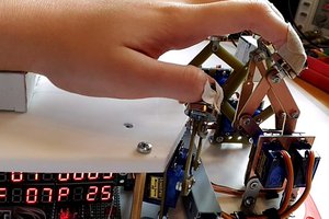
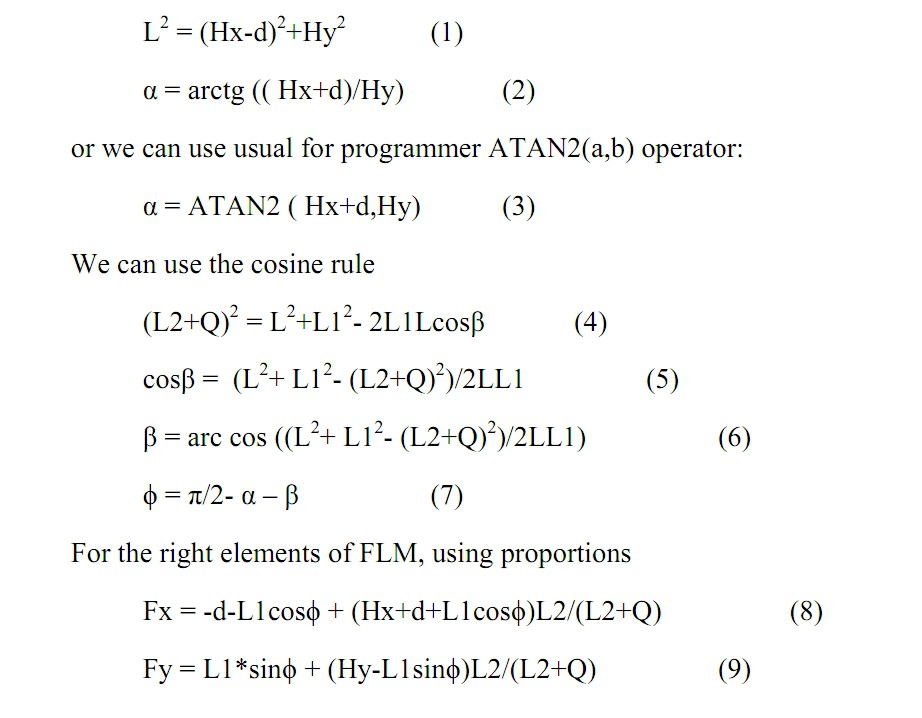
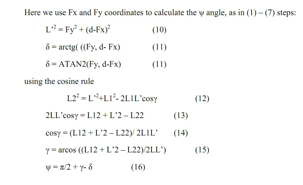
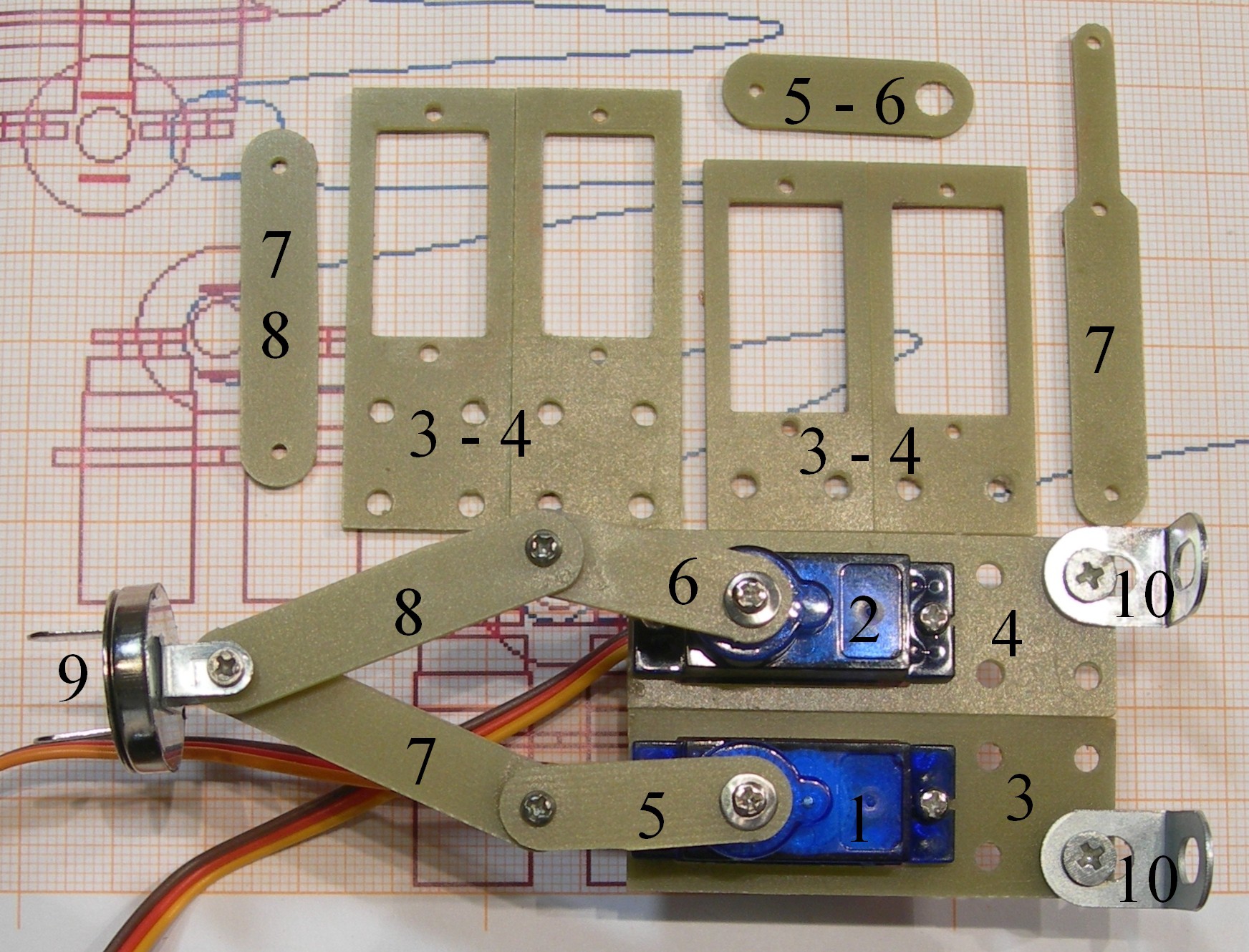
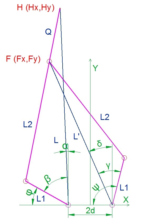
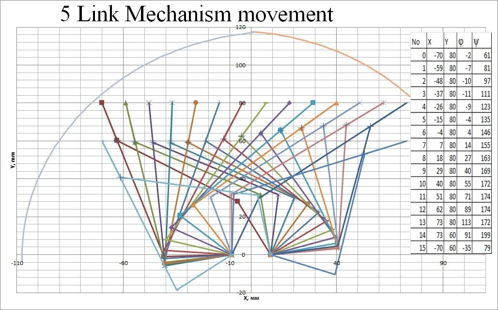
We propose very interesting and simple tool to obtain two – dimensional movement using two rotary drives and five-link mechanism (FLM). We made some math model, calculate the relations between angles and the target point coordinates. Rotary drives are servos, dc, brushless or any other motors. We can use the FLM as actuators, levers, plotter arms, pusher and feets in robots and other micromechanics.
0%
0%
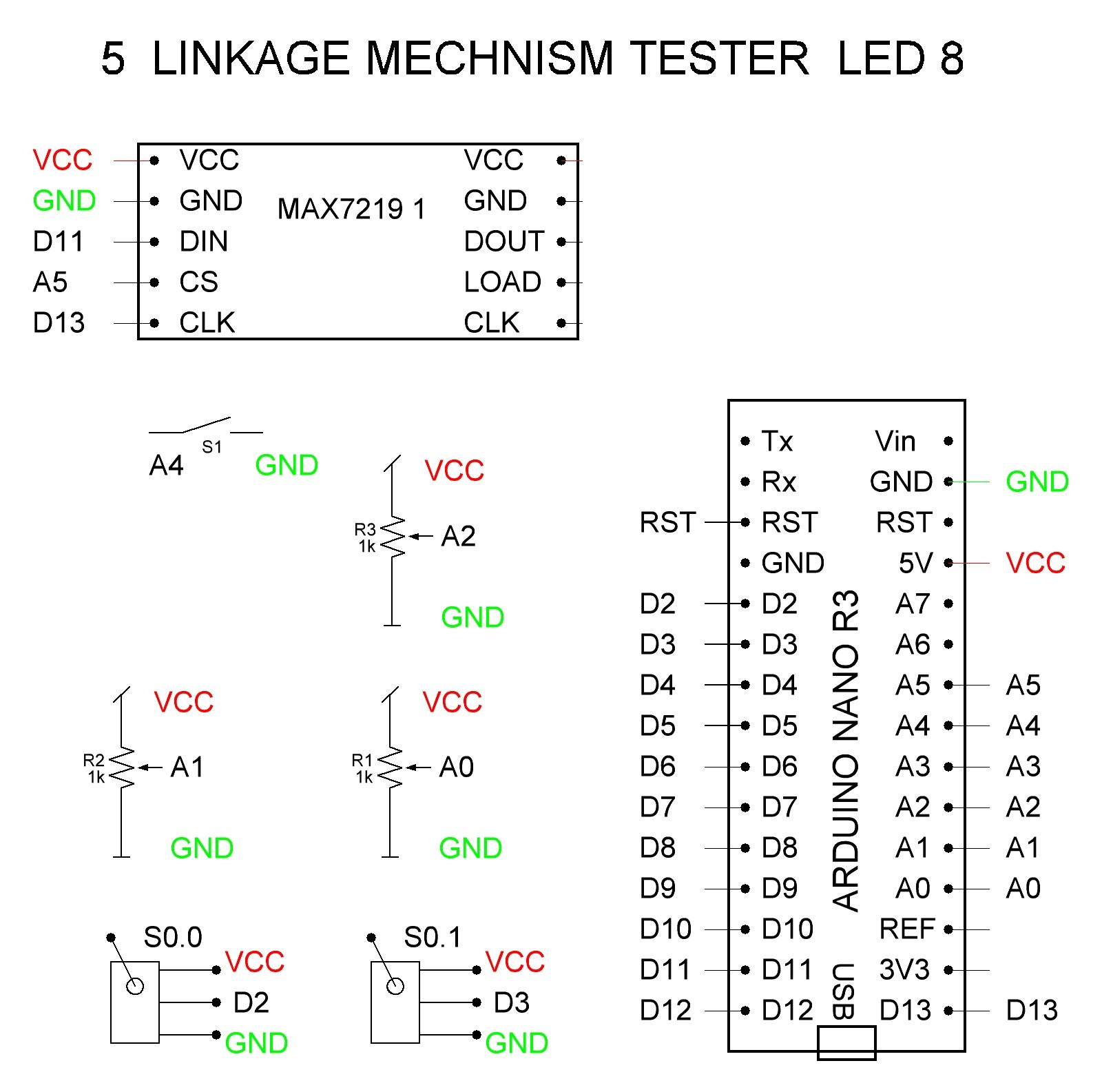
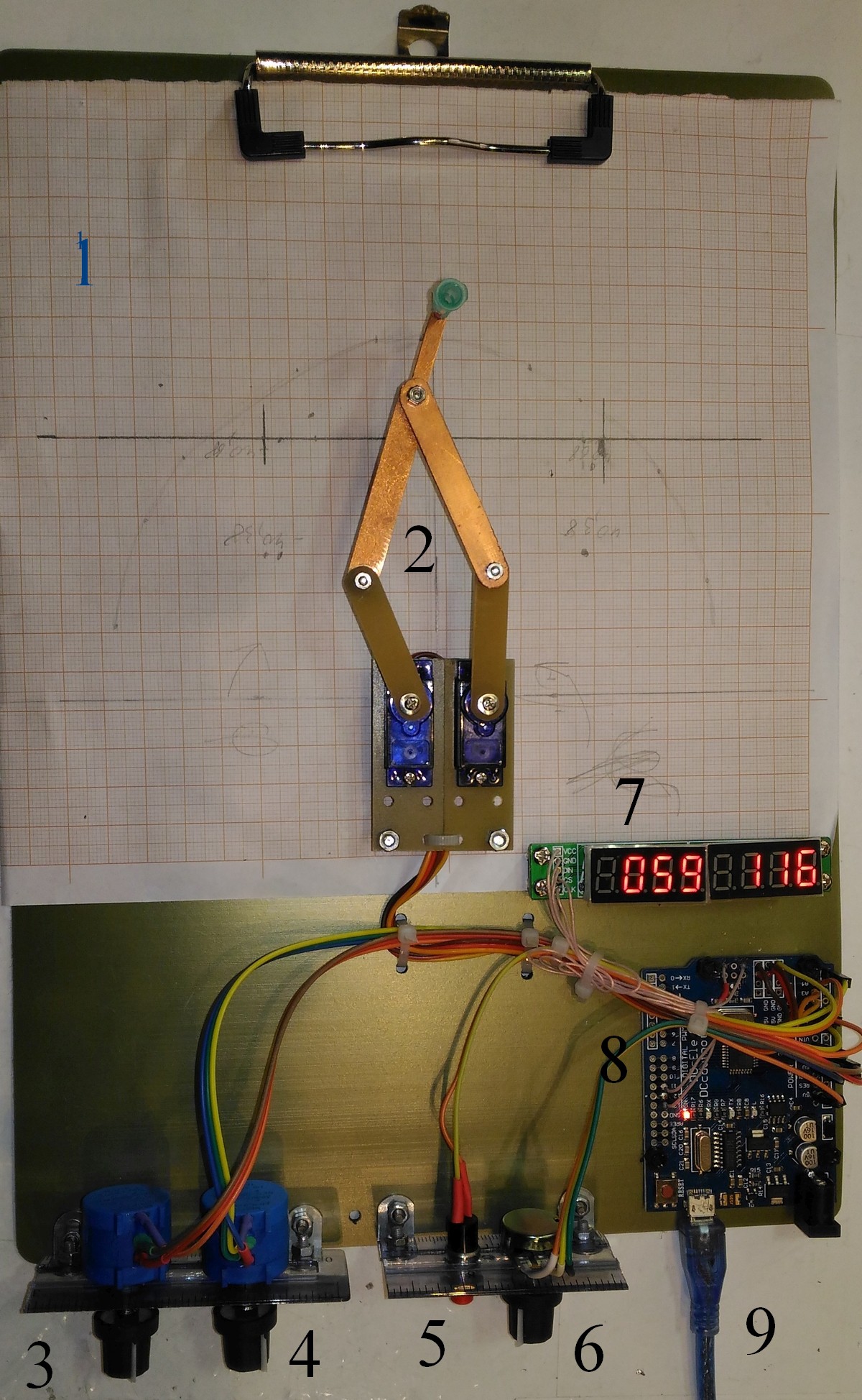
Five Link Mechanism
Five- Link Mechanism is controlled by two servos and make arbitraty 2D movement.
Become a Hackaday.io member
Already have an account? Log in.
Just one more thing
To make the experience fit your profile, pick a username and tell us what interests you.
Pick an awesome username
hackaday.io/
Your profile's URL: hackaday.io/username. Max 25 alphanumeric characters.
Pick a few interests
Projects that share your interests
People that share your interests


 Luke J. Barker
 Jackson Miller
 Nick Rehm