0%
0%
Low Cost CO2 Laser Build
Goal: To assemble a working CO2 Laser from a minimum investment
using only tools one can find at your average home improvement store.
 ThunderSqueak
Become a Hackaday.io member
Already have an account? Log in.
Just one more thing
To make the experience fit your profile, pick a username and tell us what interests you.
Pick an awesome username
hackaday.io/
Your profile's URL: hackaday.io/username. Max 25 alphanumeric characters.
Pick a few interests
Projects that share your interests
People that share your interests


 ganzuul
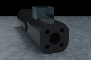
 David H Haffner Sr
 Mathieu Lacage
Hi,
I really like your project and build something similar myself right now.
Therefore, I have two questions where I really struggle.
1. The output coupler. You used 1. A mirror, 2. A flat znse window and 3. Another convex lense (probably independently of the tube, just to focus the beam to cut/engrave material), correct?
2. How did you align the mirrors towards each other? How can you set them perfectly parallel to each other?
Thanks a lot.