 M. Bindhammer
Lithium Polymer (Li-Po) is the most likely battery chemistry choice for small robots due to its high energy density and output current capabilities. But Li-Po cells can be dangerous if not treated properly. A safe Li-Po cell needs to be protected against over-voltage, under-voltage, and over-current to prevent damage to the cell, overheating, and possibly fire. The power management subsystem built into Murphy is shown in this block diagram:
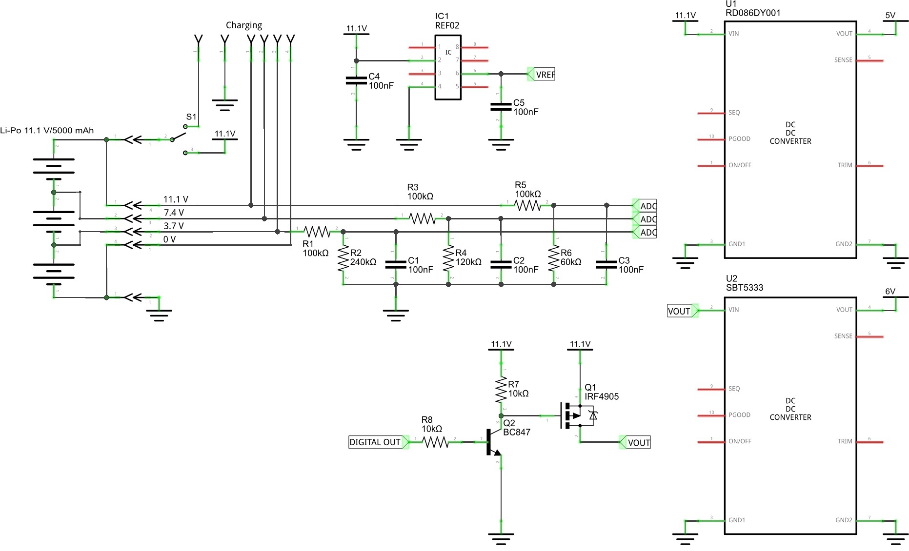
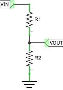
A Li-Po cell has a no-load resting voltage of 4.2 V when fully charged and 3.7 V when discharged. The Arduino is running at 5 V, so the maximum voltage we can measure with the on-board analog ports is 5 V. The balance port on cell 3 of the 11.1 V Li-Po battery can reach 12.6 V, so we need a way of reducing this to ≤ 5 V. A common way is to use a voltage divider. A voltage divider is a simple circuit which turns a large voltage into a smaller one. Theory is simple:
VREF of the Arduino is not very precise. Fortunately you can easily attach an external VREF. Therefore I added a REF02 on the board which provides a reference voltage of + 5V ± 0.2% max. Values of the resistors in the block diagram above are just fantasy values for now. You can change them as you wish. The 3.7 V balance connection port does not need a voltage divider at all. But I prefer to use at least a series resistor. Important is to keep the power consumption of the voltage dividers at a minimum. Capacitors C1 - C3 should reduce noise.
The P-channel power MOSFET IRF4905 will shut down the load (servos, motors) in case of low battery if the digital output connected to the base of transistor Q2 goes LOW. In any organism activities will be reduced to a minimum if no nutrients are available anymore. Brain will die at the very end. Same here. Brain will die at the same moment the battery will die. Instinct of self preservation is the most important instinct. It will not work if the brain dies off first.
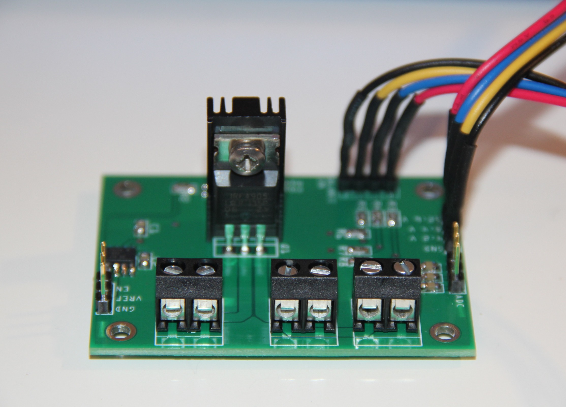
Populated and tested power management PCB:
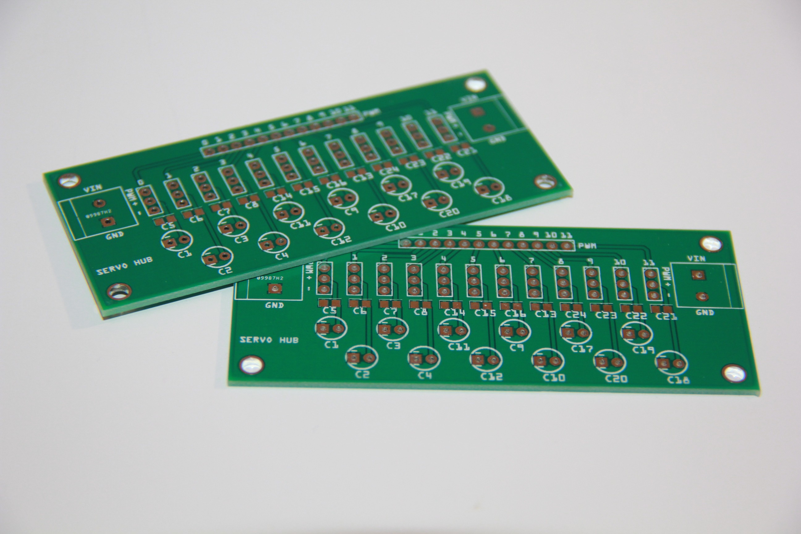
 To avoid any servo jitter I designed a special power rail for the servos. Basically every servo has its own decoupling and filter capacitor:
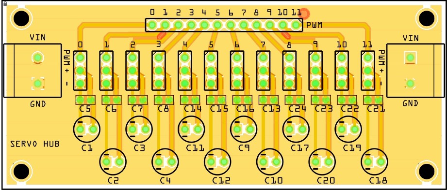
Bare PCB:
And populated PCB:
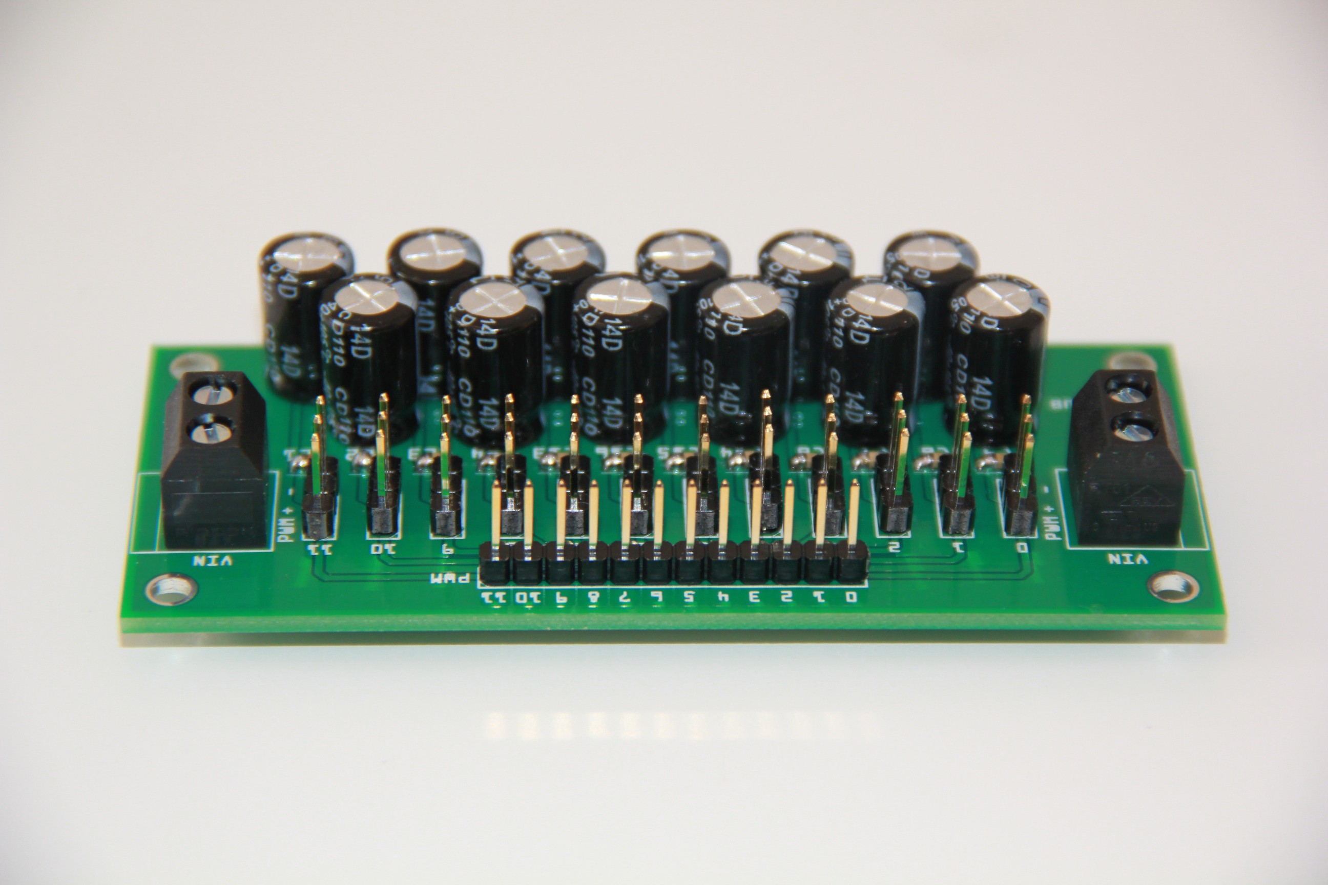
In general analog servos are more prone to jitter even with sufficient power supply so I will replace all MG 995 by its digital version MG946R.
Discussions
Become a Hackaday.io Member
Create an account to leave a comment. Already have an account? Log In.