 vmorant
This project involves the construction of a color detector from an Arduino board, a photodiode and LED RGB
0%
0%
Color Sensor
This project involves the construction of a sensor capable of detecting colors using RGB LED and a photodiode
Become a Hackaday.io member
Already have an account? Log in.
Just one more thing
To make the experience fit your profile, pick a username and tell us what interests you.
Pick an awesome username
hackaday.io/
Your profile's URL: hackaday.io/username. Max 25 alphanumeric characters.
Pick a few interests
Projects that share your interests
People that share your interests

 Roza
Roza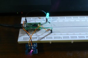
 Clovis Fritzen
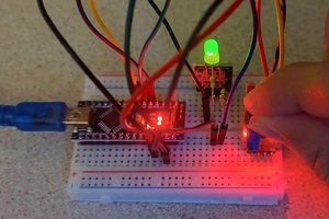
 eGuidezhan
 Alpha Charlie
Hi....I need a code which can give the photodiode's voltage output when different colors of light is incident on it with the help of RGB led. Thank you!