 Alvaro Villoslada
The problem
Electromyography, or EMG, is a technique from the medical field that comprises the recording and the study of the electric signals generated when a muscle contracts. EMG is widely used in clinical applications: kinesiological studies, medical diagnosis or rehabilitation, among others. Also, EMG is the preferred method to control robotic prosthesis or exoskeletons, since using the user's cognitive processes is a natural and intuitive way of interacting with such devices. Besides these applications, EMG can also be used in hands-free computer control, physical training optimization, interactive art...
Professional EMG systems are very expensive, cumbersome (with lots of cables connecting the electrodes to the amplifier) and
complex, and for this reason their use is usually limited to
hospitals or professional laboratories. Although there are some
portable and simpler professional EMG systems, they are also quite
expensive to be used by hobbyists or research labs with a moderate
budget.
The solution
The aim of this project is to develop an affordable and open-source wearable wireless network of EMG sensors that can be placed on any muscle. With this project my intention is to develop a hacker-friendly biofeedback interface to control devices ranging from computers or smartphones to robots with EMG signals. It can also be used simply as an instrumentation system to view and analyze the acquired EMG data. Although it probably cannot be compared with professional systems in the market, the EMG signal acquisition circuit is carefully designed, using low-noise components and techniques for active suppression of mains hum. Wireless communication allows the use of multiple sensors without the large number of cables that this type of devices usually have. Also, the wireless architecture allows for a great flexibility since there is no fixed number of acquisition channels.
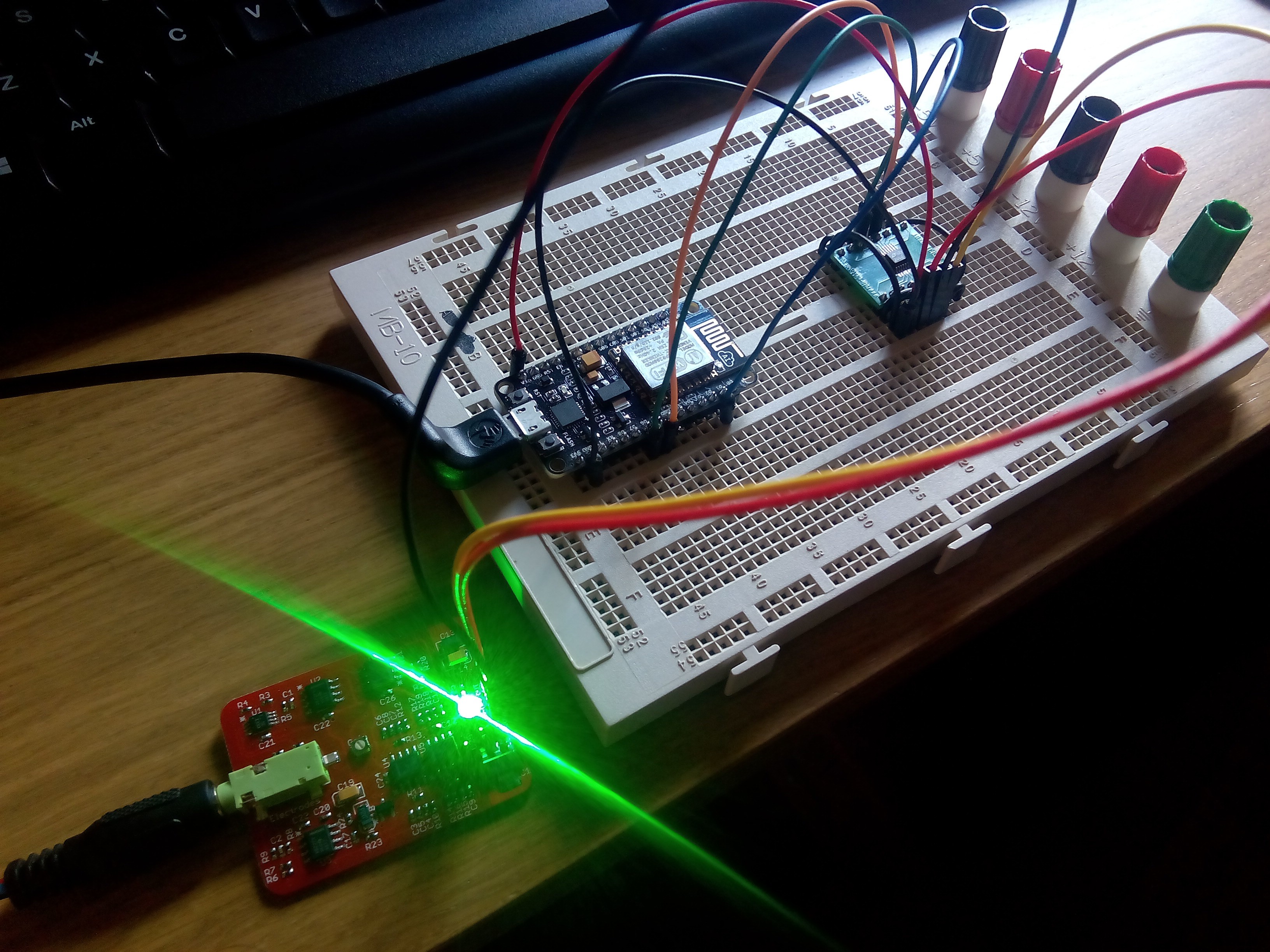
Each EMG sensor is connected to a ESP8266 module, forming a Mumai node. The nodes send the EMG data through WiFi to a computer, smartphone or other devices, such as a robot or a home automation system. The following diagram summarizes how this interface works.
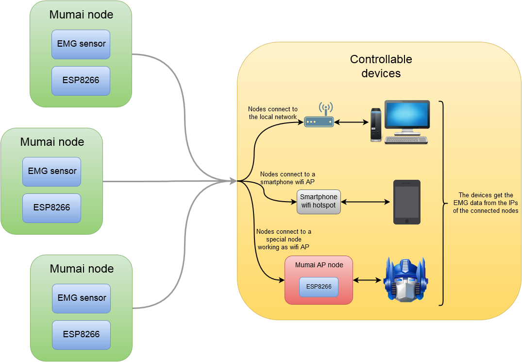
There are three ways this interface works, depending on which device the nodes connect to:
- Computer interface: Mumai nodes connect to the local WiFi network to which the computer is connected.
- Smartphone interface: Mumai nodes connect to a WiFi access point created by the smartphone.
- Device interface: Mumai nodes connect to a WiFi access point created by an extra node connected (through UART, SPI, I2C...) to the device to be controlled.
In all three modes, the controlled device retrieves the EMG data of each node accessing to its corresponding IP address. In each case, some kind of software is in charge of this (e.g. a Python script in the first case, an Android app in the second case or an Arduino program in the third case).
It should be clear that Mumai is just an interface to transmit EMG data from any muscle to a variety of devices, it is a bridge between your body and the device you want to control. How the data provided by this system are used is up to you. I will post some use cases on the project logs, as well as on the Github repository, that may serve as examples of how Mumai can be used.
Features
- Raw EMG signal output.
- Low-noise, high quality signal.
- Easy to setup and use.
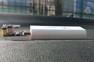
- Compact and comfortable to wear.
- Fully open-source.
Use cases
License
This work is licensed under a Creative Commons Attribution-ShareAlike 4.0 International License.
The EMG sensor used in this project is based on my MSc thesis, where more information regarding the design and operation of the circuit can be found.


 Costin Stroie
 make2xplore
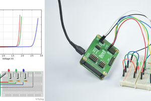
 Kuldeep Singh Dhaka
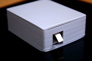
 Shebin Jose Jacob
Wow, I'd love to learn more. My daughter and I have been working on an assistive robotic arm since her arm was paralyzed a few months ago. We are now trying to find a way to create open source myoelectric signal recognition software. We have been using proprietary software but will not be able to afford to licence it, especially as we are also trying to help the thousands of other children like my daughter too. You can read our story here: https://www.linkedin.com/pulse/i-didnt-expect-doing-bodo-hoenen
Is there a way we can get in touch, share resources, skills, advice? I also have the project here on hackaday: https://hackaday.io/project/13308-building-a-robotic-prosthetic-arm