 shane kirkbride
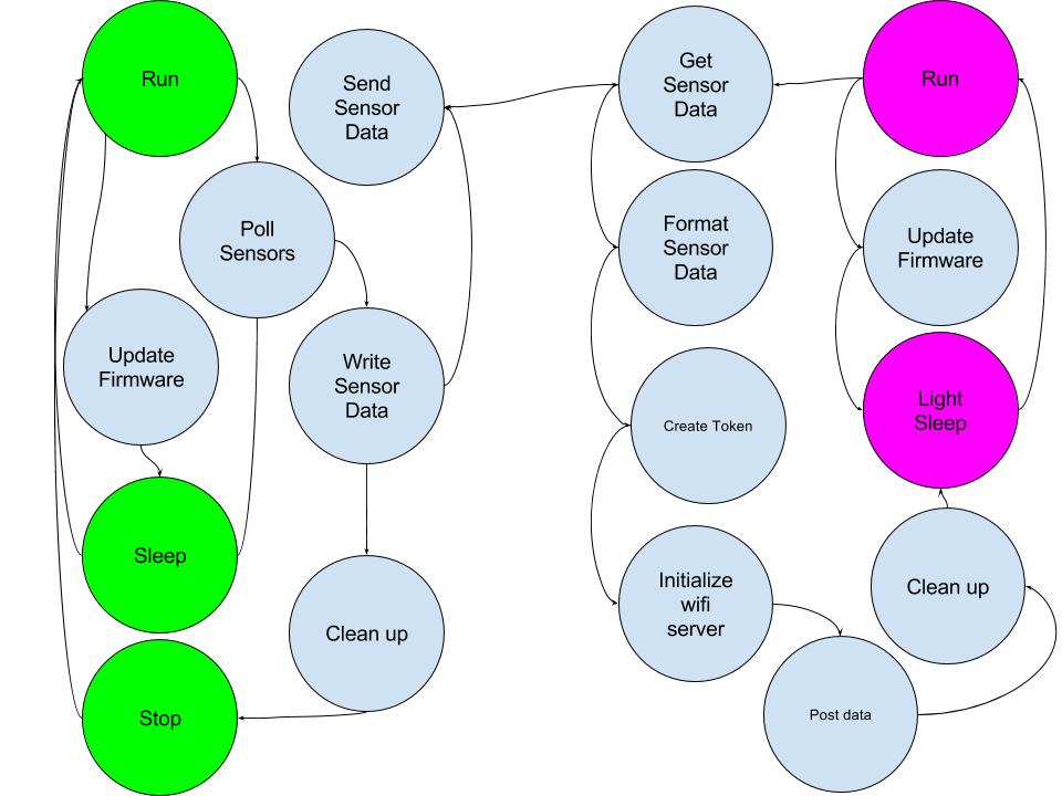
The two main IC’s the software will live on is the ESP8266 ESP-02 and the STM32F446RET6. I’ll call these the ESP and the ST-chip respectively. Each chip has low power options on it. These low power options will be key to giving this board a battery life of 2 years. At first we thought to do an implementation with an RTOS, such as Zephyr. The boards that support Zephyr are here: https://www.zephyrproject.org/doc/board/board.html these boards are more expensive and consume more power than would be appropriate for this project. The same functionality with more control over the power states with a bare metal implementation is something that can be more readily accomplish. The goal will be to consume less than 500mA of power while the system is in the run state with a BOM cost of less than $15 (When built in quantity). The updated embedded firmware state diagram is shown below. This is a very high level state diagram and should only be used to illustrate the intended functionality of the system. The green circles represent the power states of the ST chip. The fuchsia circles represent the power states of the ESP chip. Within the run power state of each device the majority of the work occurs. Clearly right now we are thinking a lot about how to minimize the amount of power while making sure the system meets all of the functional requirements. From the run states we either update the firmware or we do I/O management. Once the sensor data is managed appropriately. Some data clean up occurs and the devices are set into their low power states. The devices will be triggered to wake up by a timer.
Software Overview
A project log for SunLeaf
A solar powered wireless picopower sensor module with cloud Datalogging and control geared towards agriculture and environmental monitoring
Discussions
Become a Hackaday.io Member
Create an account to leave a comment. Already have an account? Log In.