 [skaarj]
Allright. The first round reward was like a deep fresh air breathe, because I managed to fix most of the bad issues of the automobile mechanics. These are the completed steps:
- front and back springs replacement;
- rear axle replacement;
- new carburetor;
- most of the engine gaskets replaced;
- the entire steering mechanics upgraded;
- brake system upgraded;
- finalize all paperwork plus pay legal taxes in order to receive a big place to setup a local hacker space and laboratory.
And of course a nice romantic dinner for my lovely wife, which can still not believe how such a competition and a reward is possible for such an old rusty vehicle - which by the way caught rust AGAIN at trunk side. It needs serious body repairs [lot of time, a lot of money, not sure how seriously the work is done] , or even a new body [less money, less time, but it requires many taxes for the local "DMV" authority -Romanian Automotive Registry or the "RAR"]. There are some left-overs at the Dacia Factory, it may be possible to find something.
So good news: I am no longer forced to work under cover. She now tolerates my operation and even helps me by using her strong financial accounting background experience.
Now back to serious stuff. It's time to show you people how I built the computer terminal. Basically it's a dual-oscilloscope+color television used as a composite monitor which receives video signal from a RasPI II - B. It also houses the Arduino and a 12V to 5V power regulator to keep both working in stable conditions.
Unfortunately... reward did not arrive in time to build the oscilloscopes. So I will keep this step for the next round - Citizen Scientist - if the jury will again be merciful.
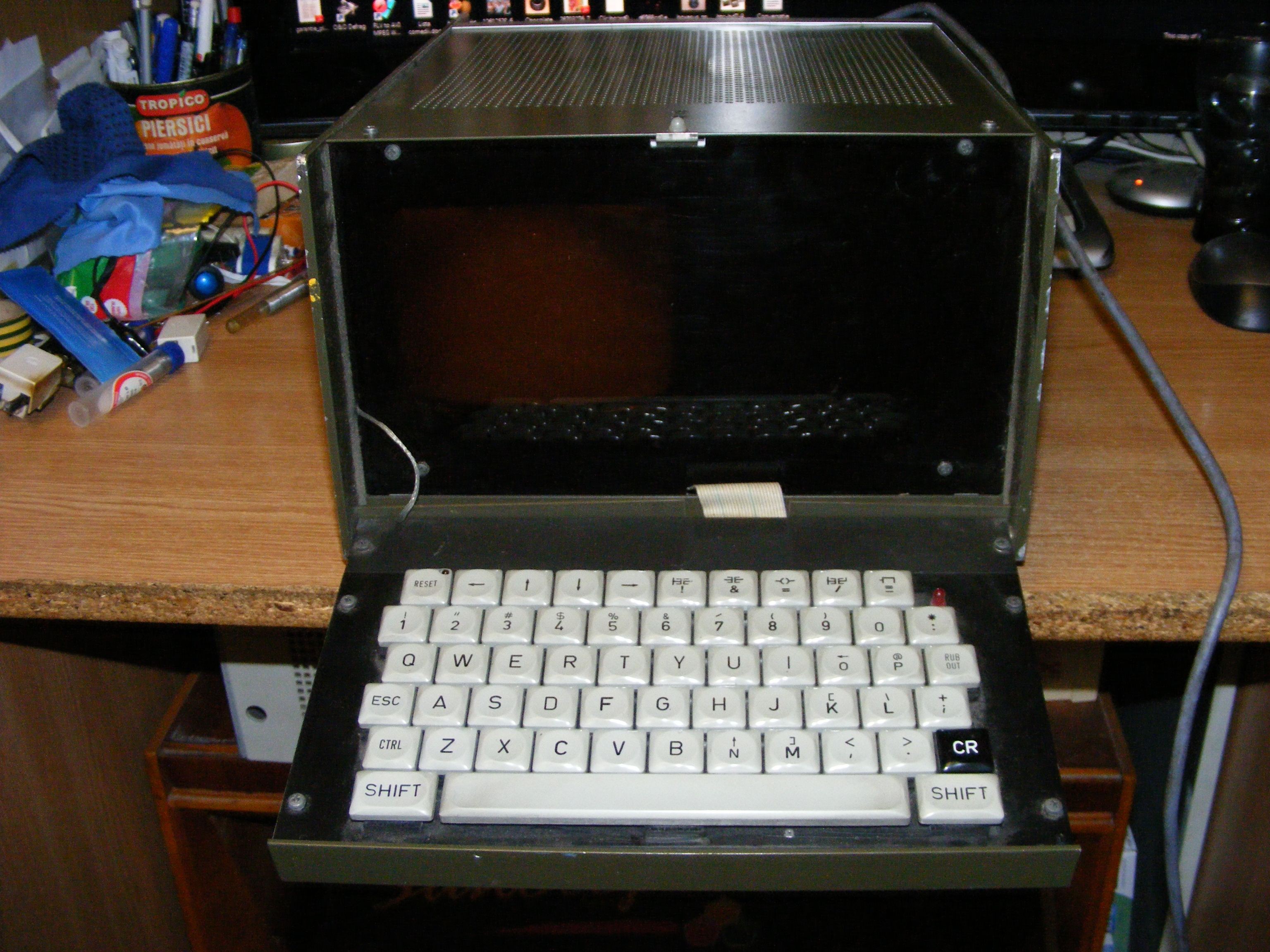
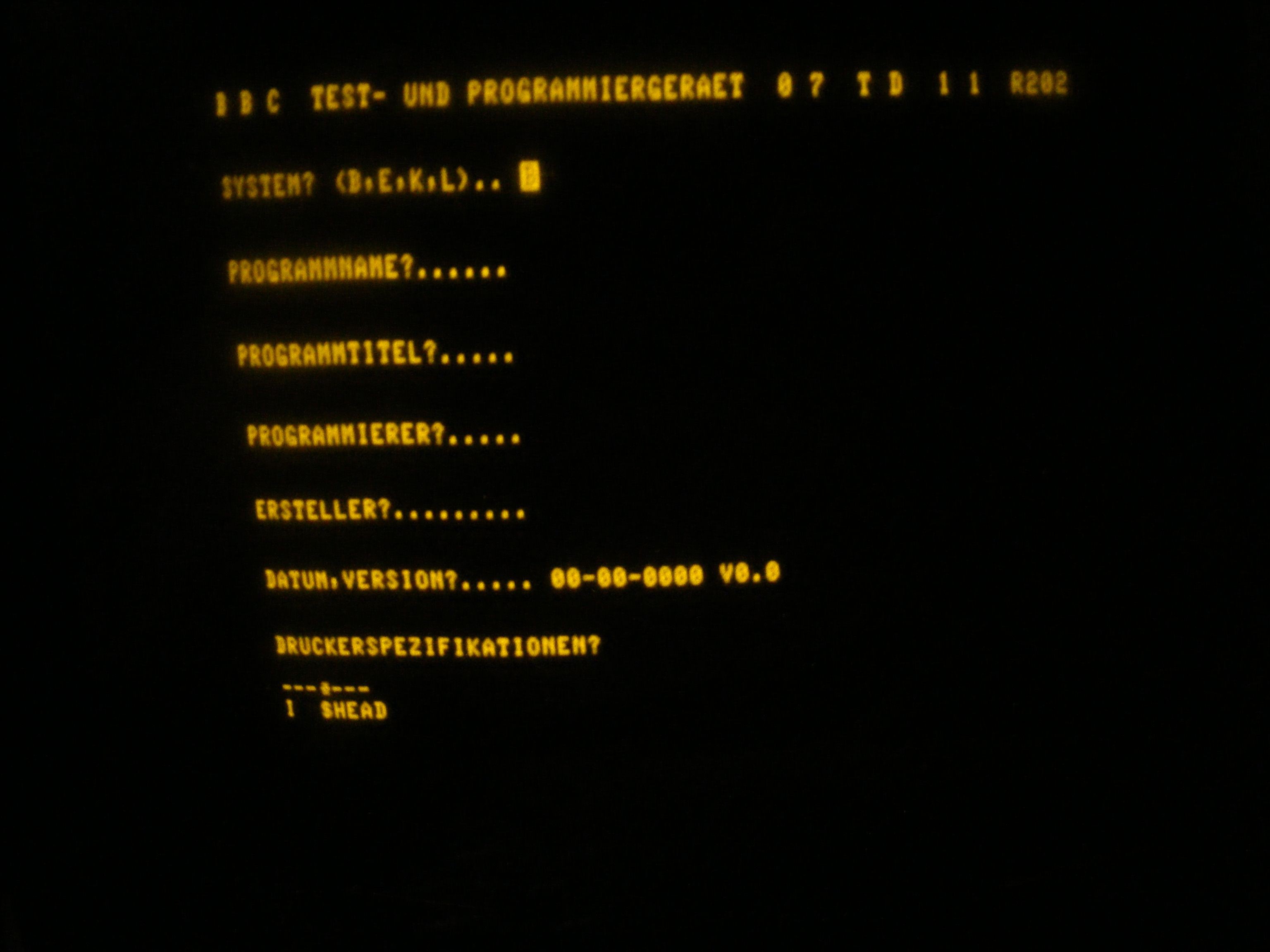
Around a year ago, a friend sent me this little monster: an old missile guiding system programmer made in 1982 in Western Germany. It has some console program, a monochrome monitor and a Z80-based main board.
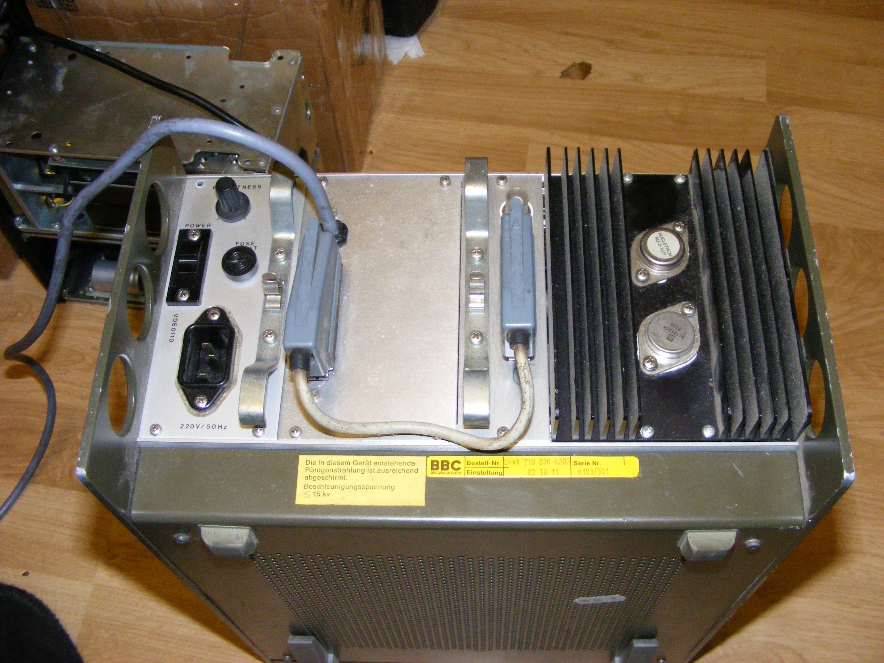
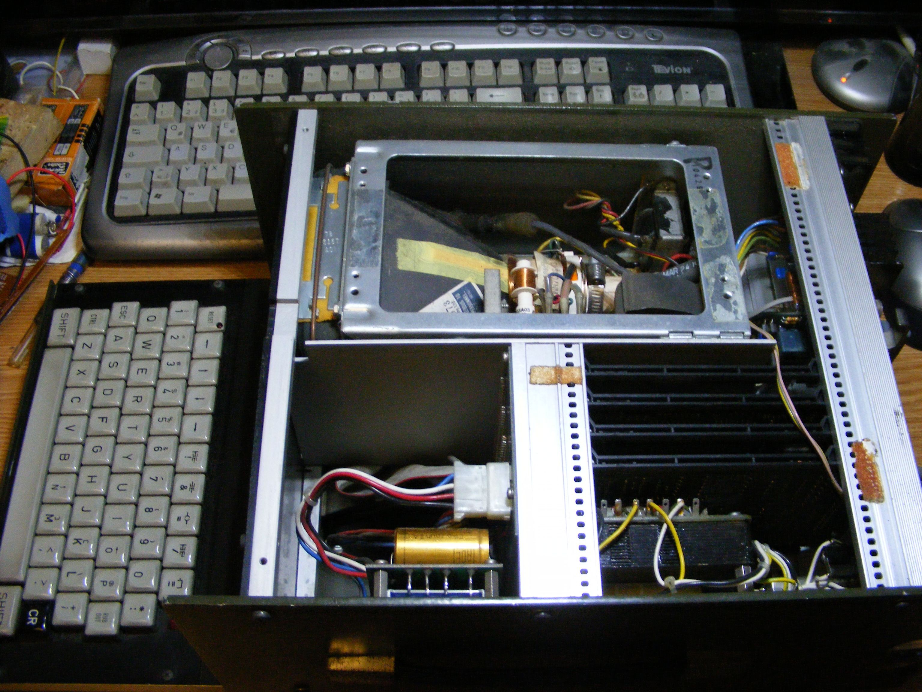
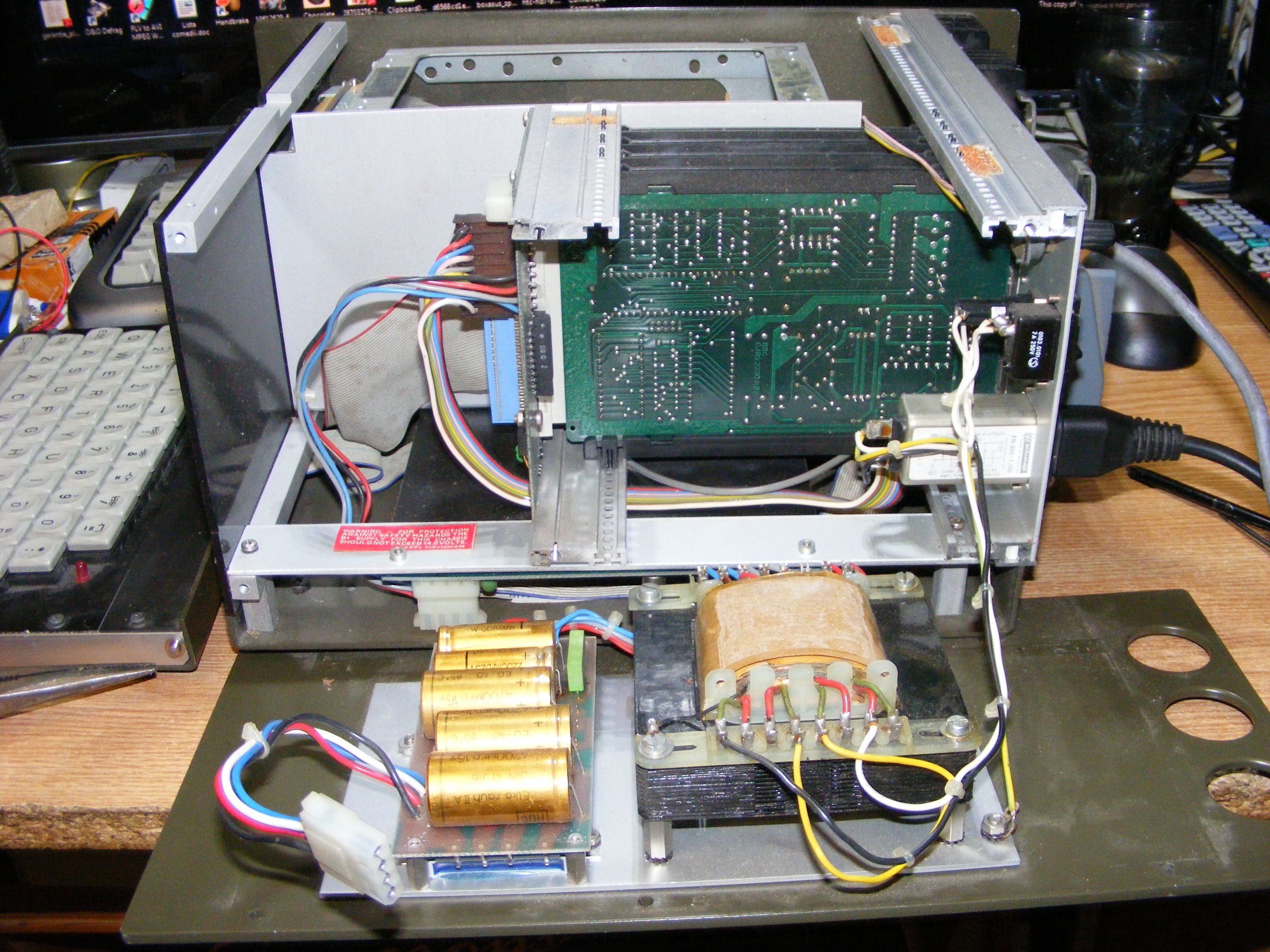
Under the bottom cover there's a motherboard with a lot of EEPROMS and a Z80CPU.
These lateral boards are the interface with the rocket guidance. I have seen soviet missile tech from that era but it was entirely subminiature vacuum-tube based but they also had programming ports. This equipment was manufactured in Western Germany in 1982.
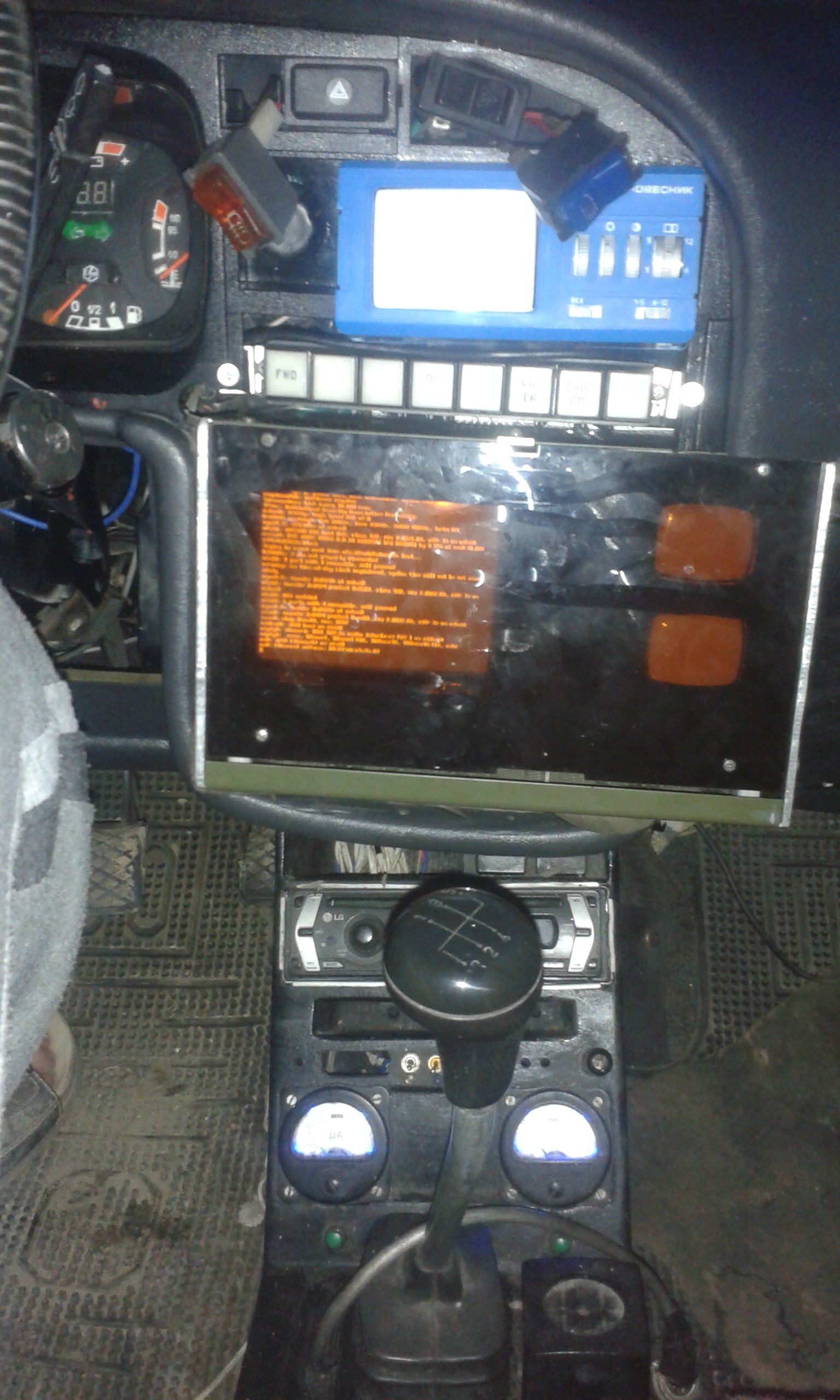
This is the first screen of the guidance programming:
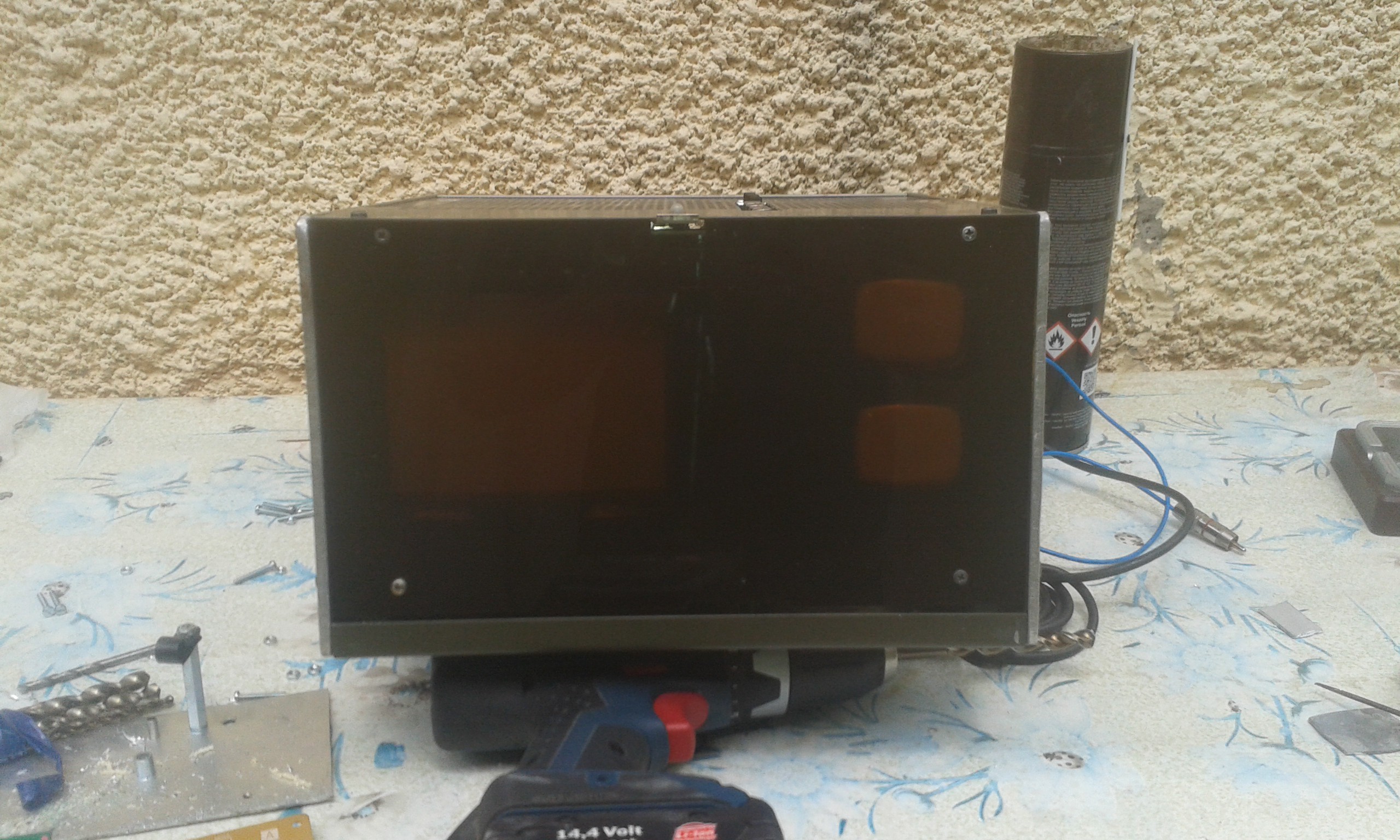
So I took everything out and inserted a 5" color CRT tube from some Japanese TV branded as "Crown". And of course the TV electronics.
I kept the old monitor plus boards in some box. Maybe I will add an extra-CRT for retro satellite navigation as @Benchoff suggested.
Following the concept desigh drawings, two additional CRTs (DS5-100W) were added:
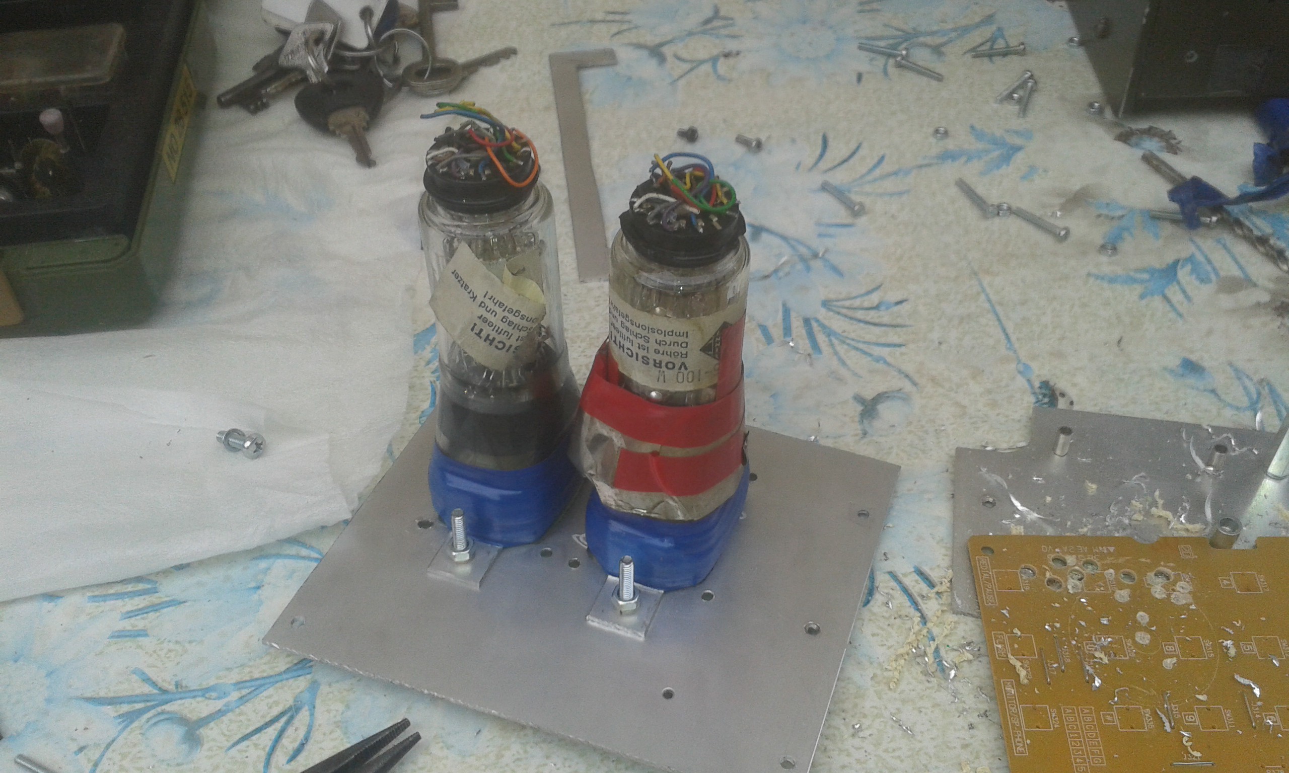
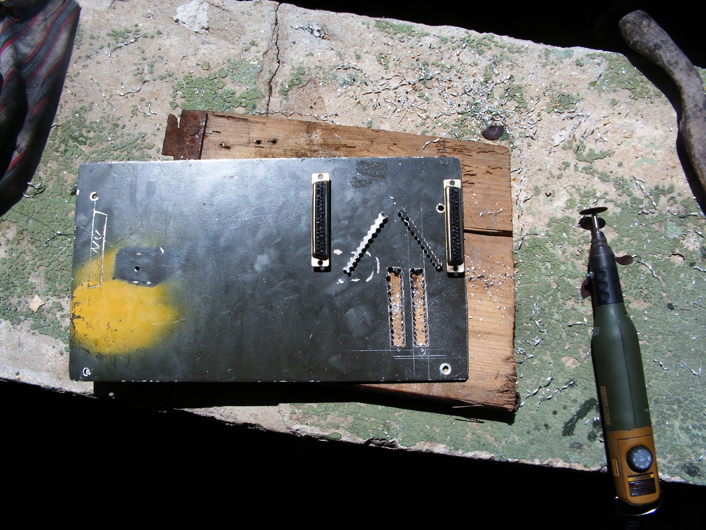
That aluminum sheet was cut by hand using my small dremel tool.
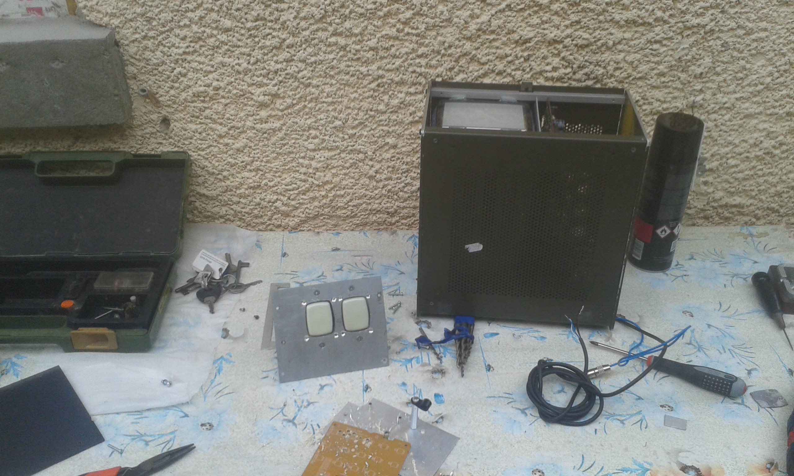
The mask needs an update:
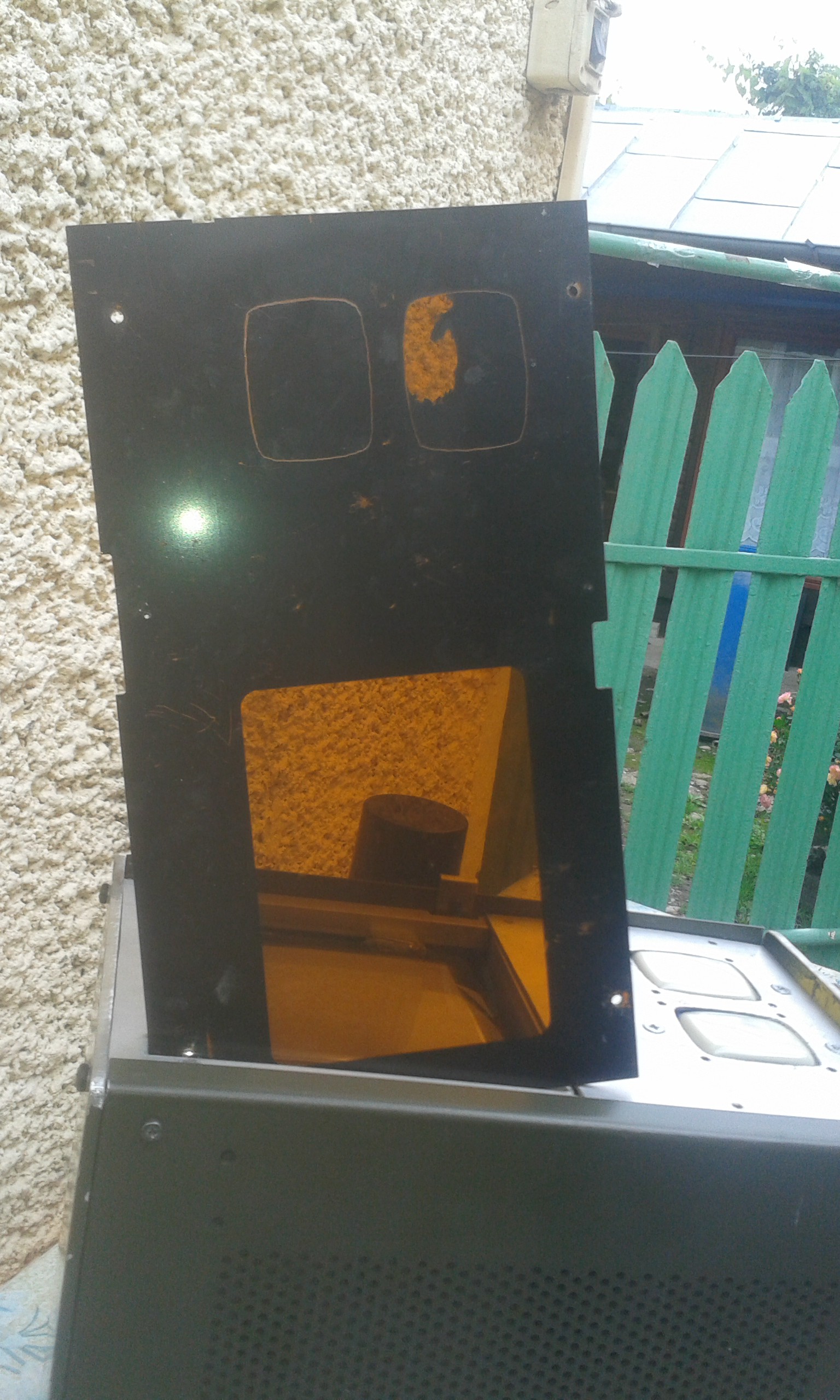
The paint removal was performed with a razor and tons of patience.
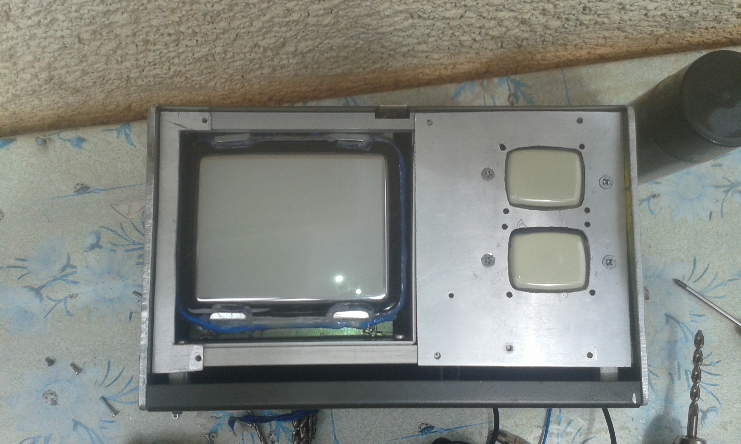
And this is how it looks like.
Of course I will need a new plexiglass mask. This one has a strange property - it removes most of the blue color and some percentage of red color, resulting a nice sepia effect which I am not sure I want to keep. So please advise.
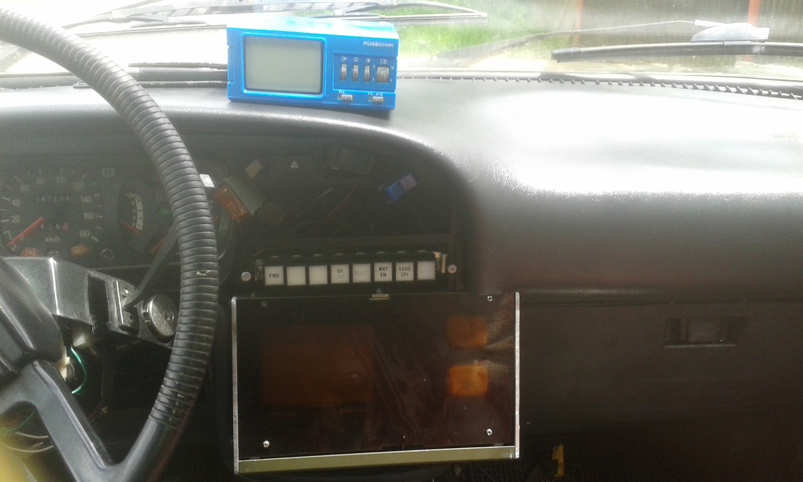
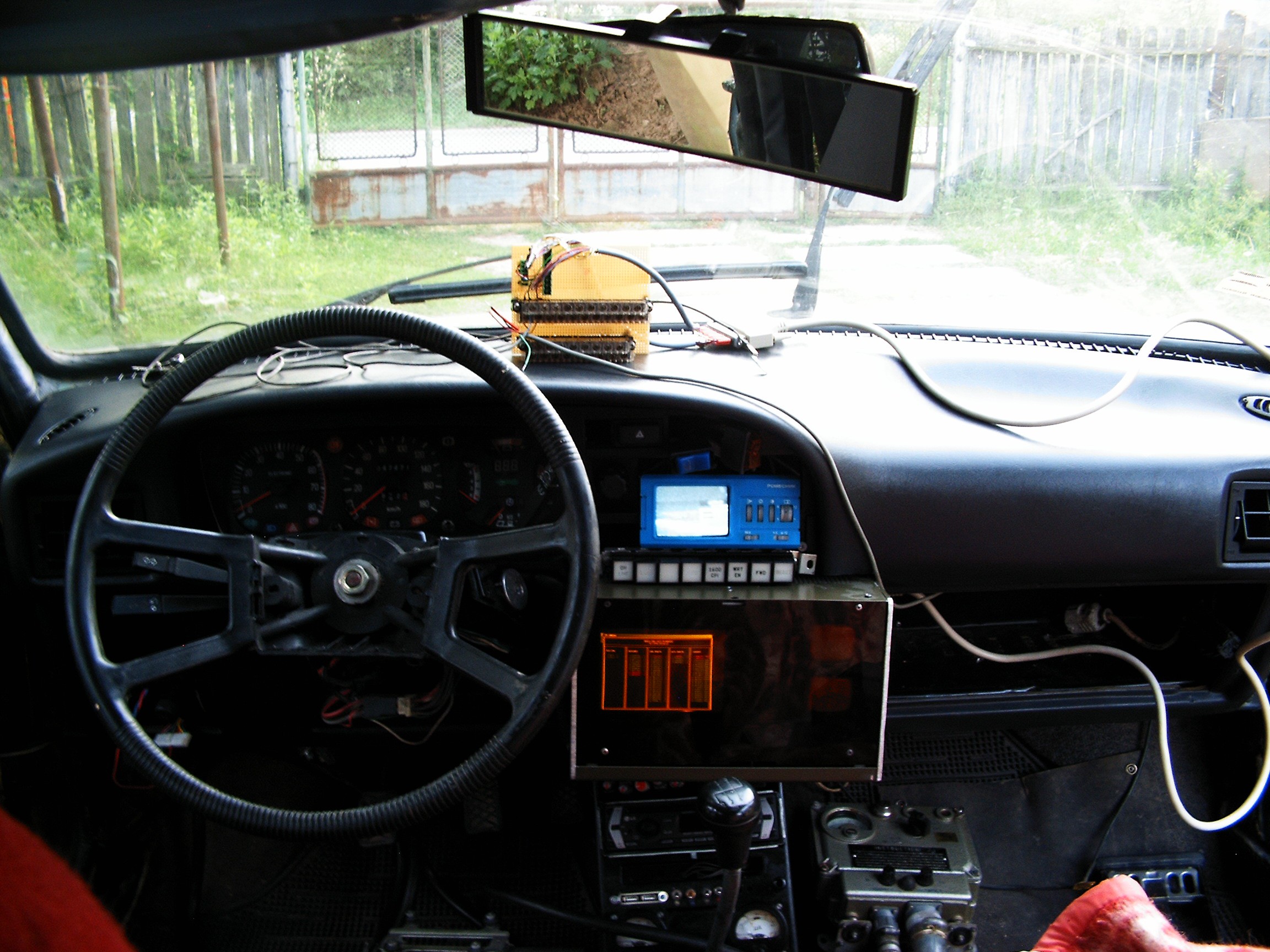
Placed in the car, the tiny terminal looks amazing.
I had to remove the keyboard, it was uncomfortable while shifting the gears. The keypad above is enough.
Due to the late arrival of the first round reward, I was unable to order the parts to build the electronics for the two CRTs. For now they are just for decoration, no oscilloscopes at this time.
RasPI 1-A booting FreeBSD 11.0-CURRENT, video connected to AV-IN.
The first key in the left (labeled as FWD) starts the system. The other key functions are as following:
1. Vehicle cabin ventilator start/stop;
2. Rear window defroster start/stop;
3. fog lights start/stop;
4. 220Volts start/stop;
5. CB Radio on/off;
6. Radiation detector;
7. Terminal screens cycling - switch between diagnosis programs, dials, gauges, graphs.
Keys will be re-labeled. And of course - work in progress - it would be nice for each button key to be illuminated. Still not sure about the color. White or green? Please advise.
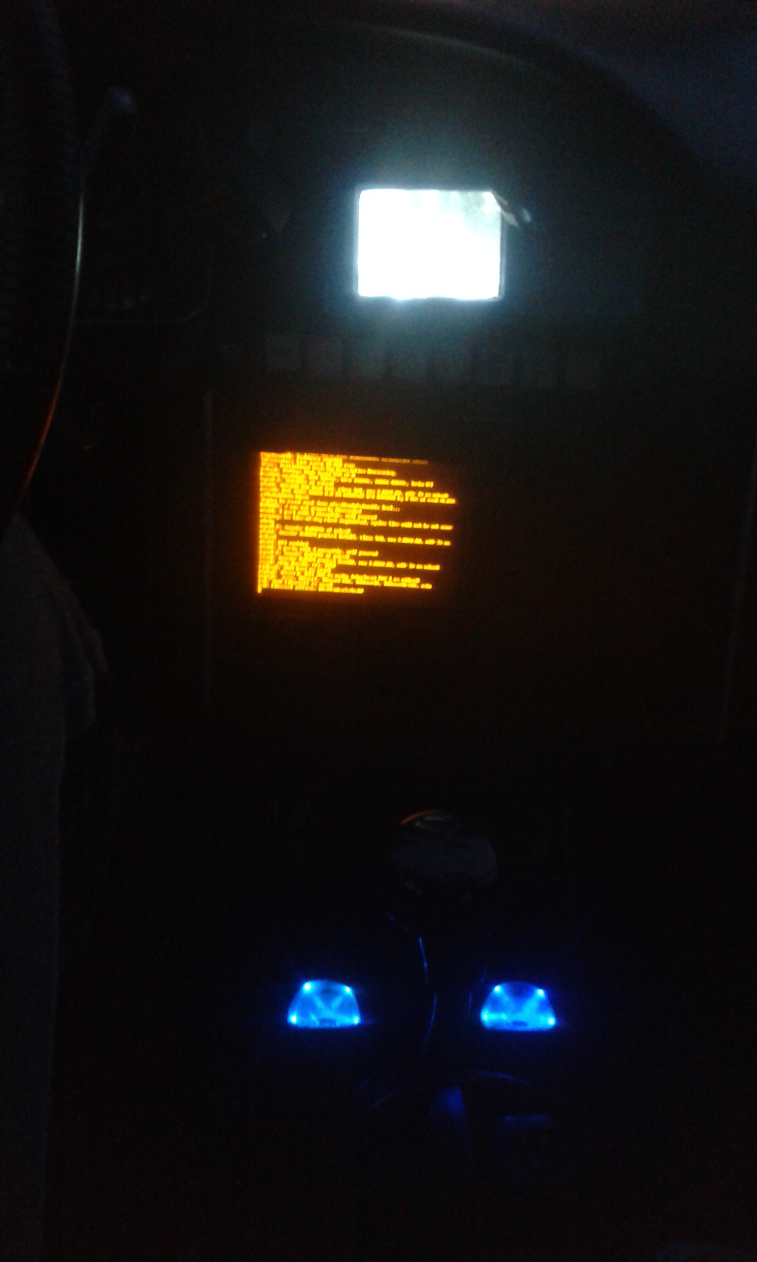
At night time it looks SF-like.
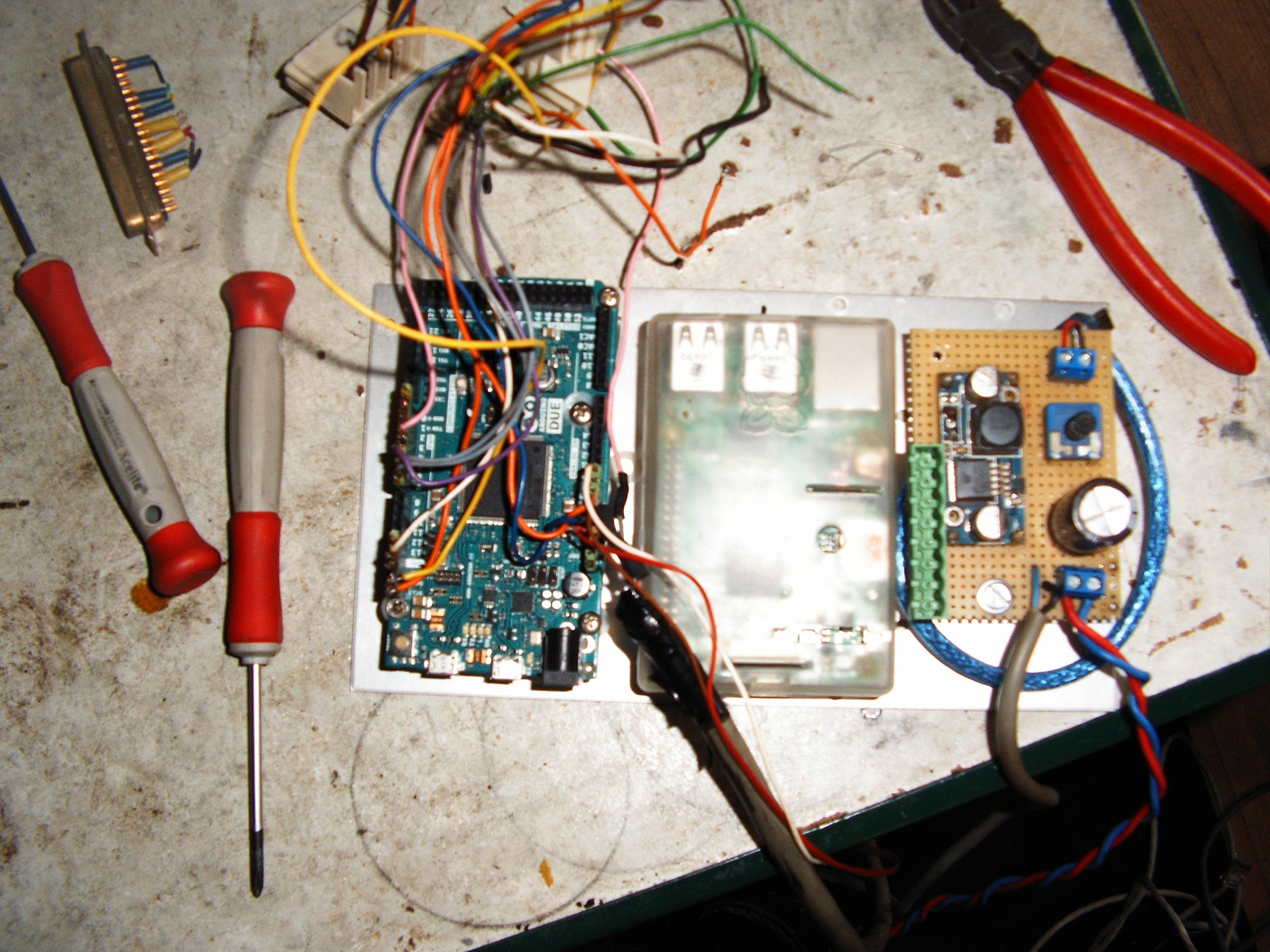
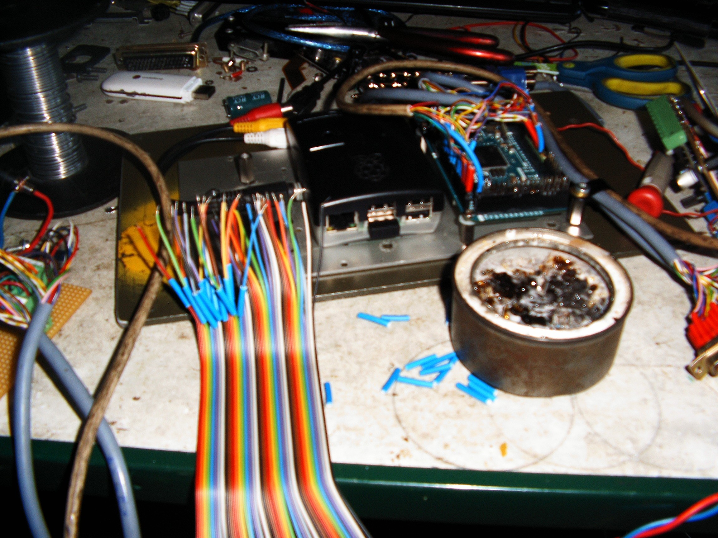
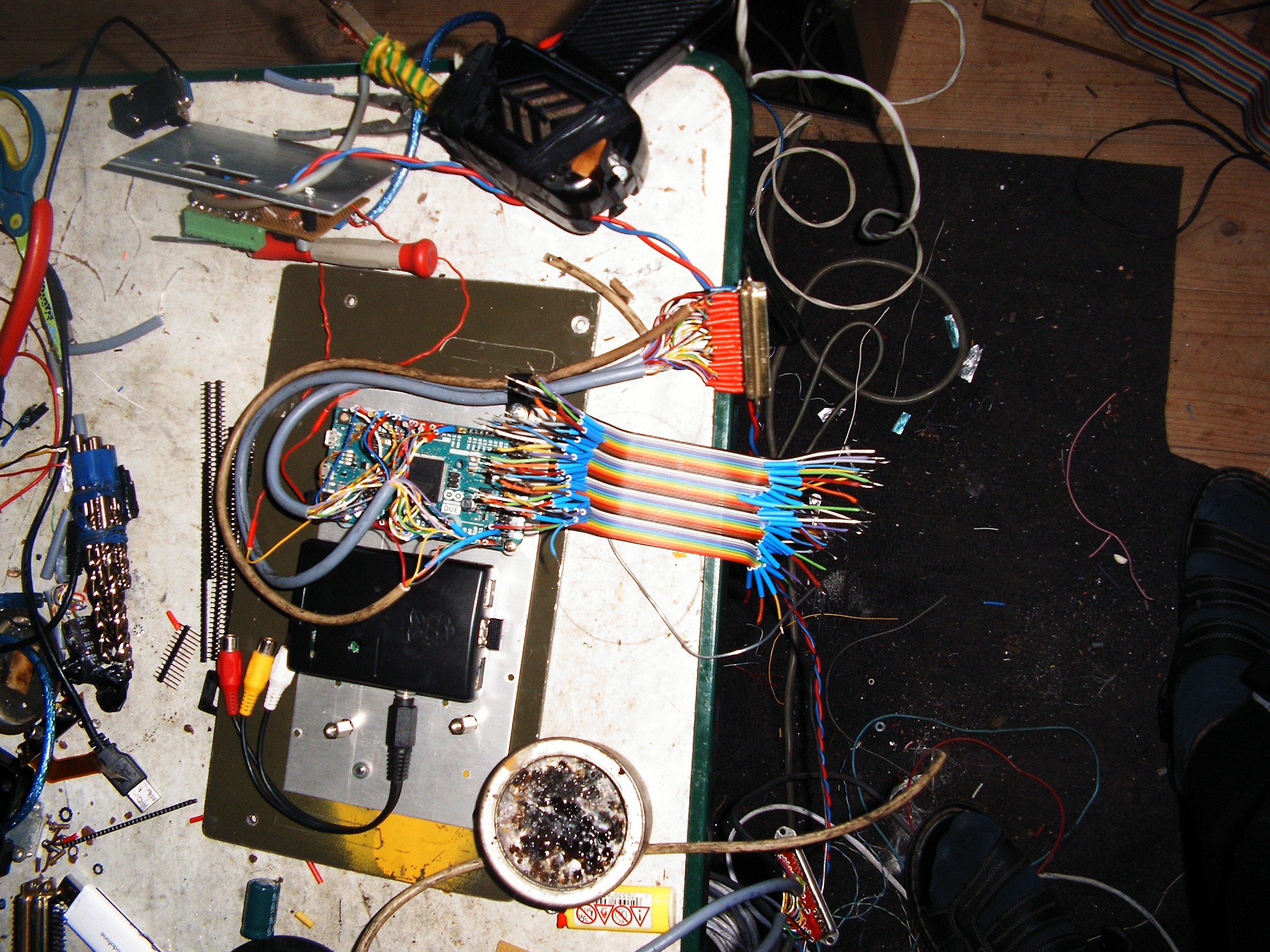
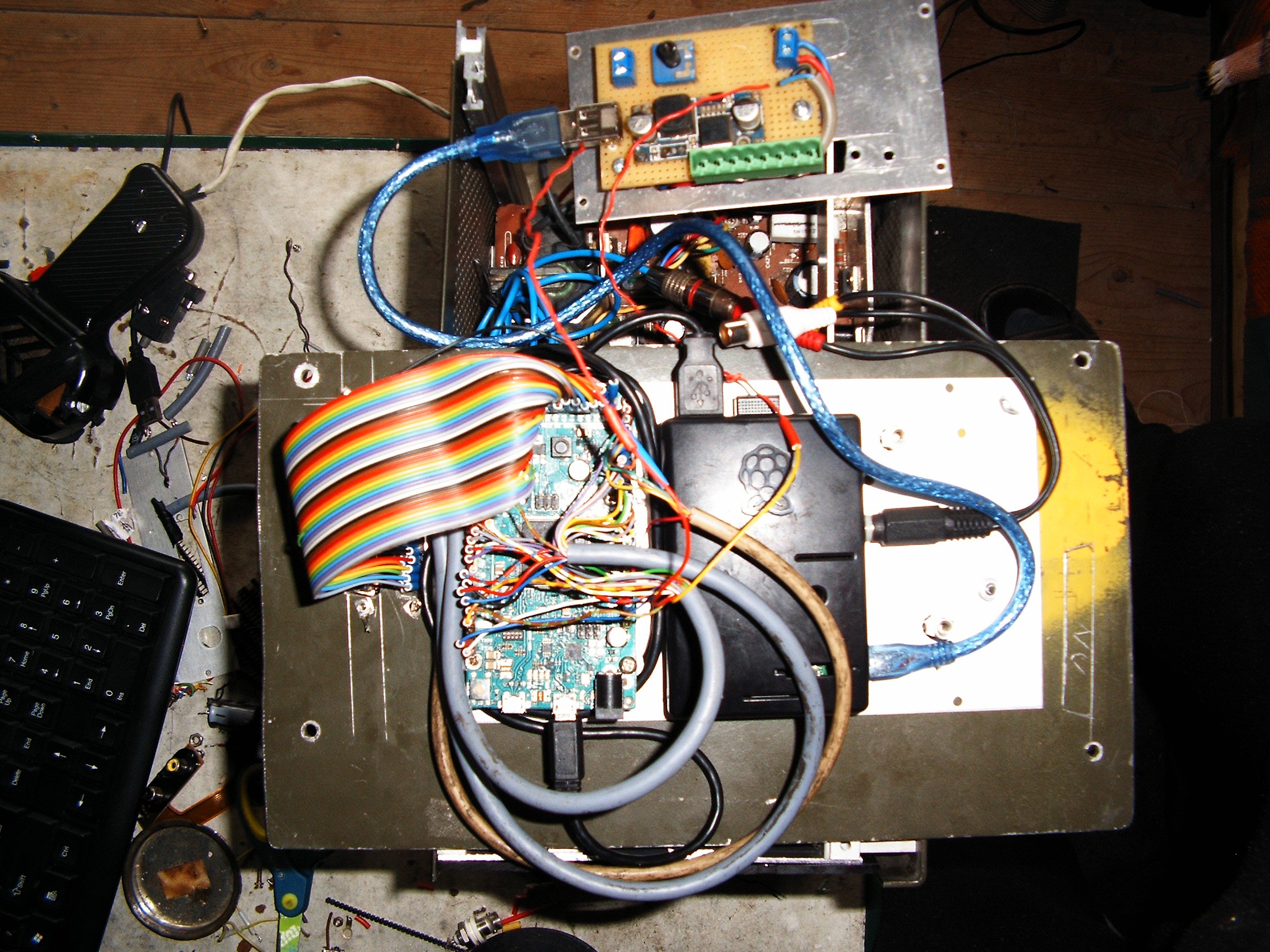
We have my big love - Arduino Due, a RasPI 2 and a 12V to 5V power regulator. Green connector is 12V to power both the color monitor and the small blue TV.
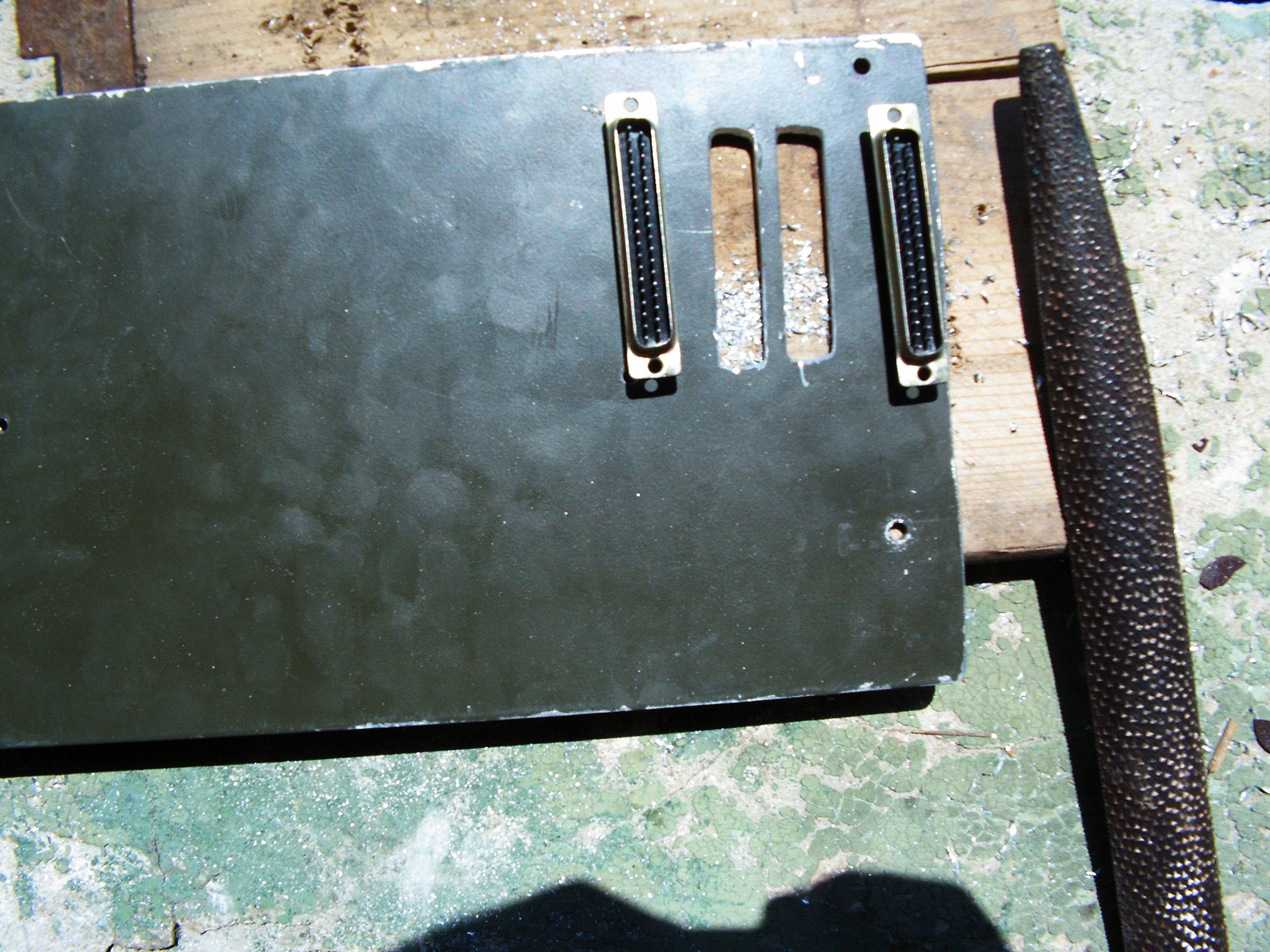
Somehow I must interface the Arduino with the outer world. I don't want to take out the terminal computer each time I want to install a new sensor. Two DB37 connectors would be perfect:
- one DB37M for analog inputs and the standard digital i/o pins (those common with the others Arduinos) - this one will have its connections vibration-protected with red extra-coatings;
- one DB37F for the extra-ports specific to Arduino Due only. This one will have its connections vibration-protected with blue extra-coatings.
And of course a big pile of papers where I will draw some tables and chose which i/o pin goes to which DB37 pin.
Whenever I want to connect new stuff, I just play in the Junction Box. No more connectors? No problem, I build another junction box.
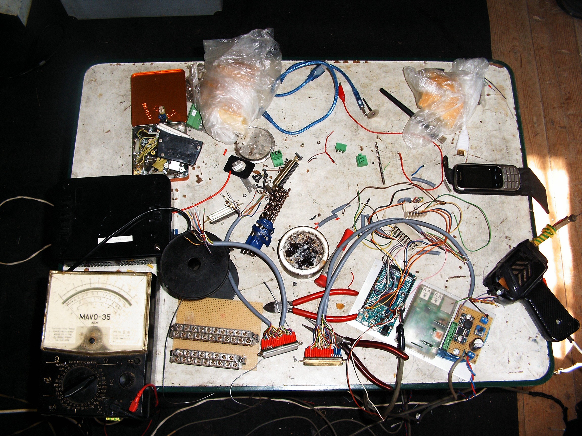
Left side - my old analog meter. Above it - black box - 12V/5A
power supply.The yellow PCB with those two connectors - the future
junction box where all the sensors will be connected.
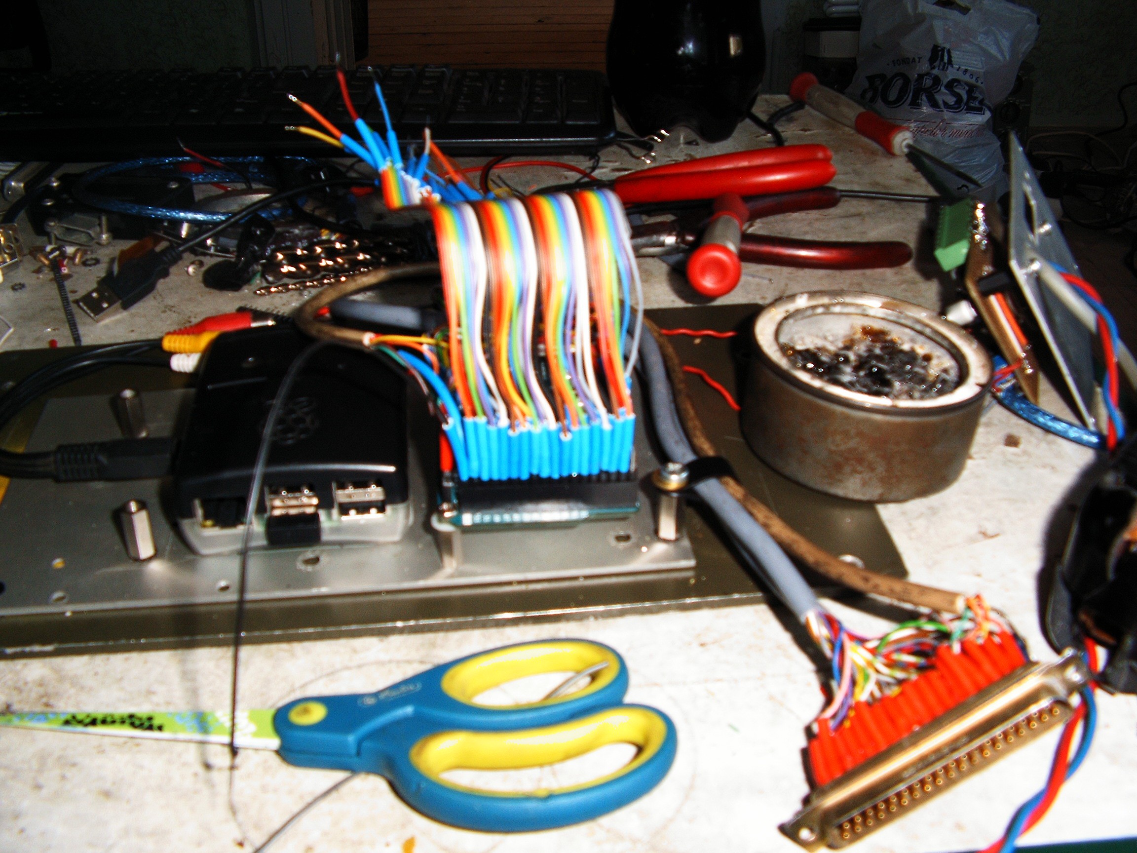
They say "they don't build them like they used to". Building retro equipment also needs special ingredients, such as old-school building style, old-school hacking and old-school optimism. Those DB37 connectors had special care for every single wire - soldering protection against vibrations and cable breaking with normal cable coating.
If you dismantle any old computing device from the 60s.....80s, you will find the same arrangements. Each connection is treated carefully. It takes a lot of time to finish but it lasts for many life times. That is why all those huge monsters costed millions of dollars. Half of that price was the high quality manufacturing. Show me a modern equipment today that follows those old rules - except army issued devices.
Every single wire has the protection inserted.
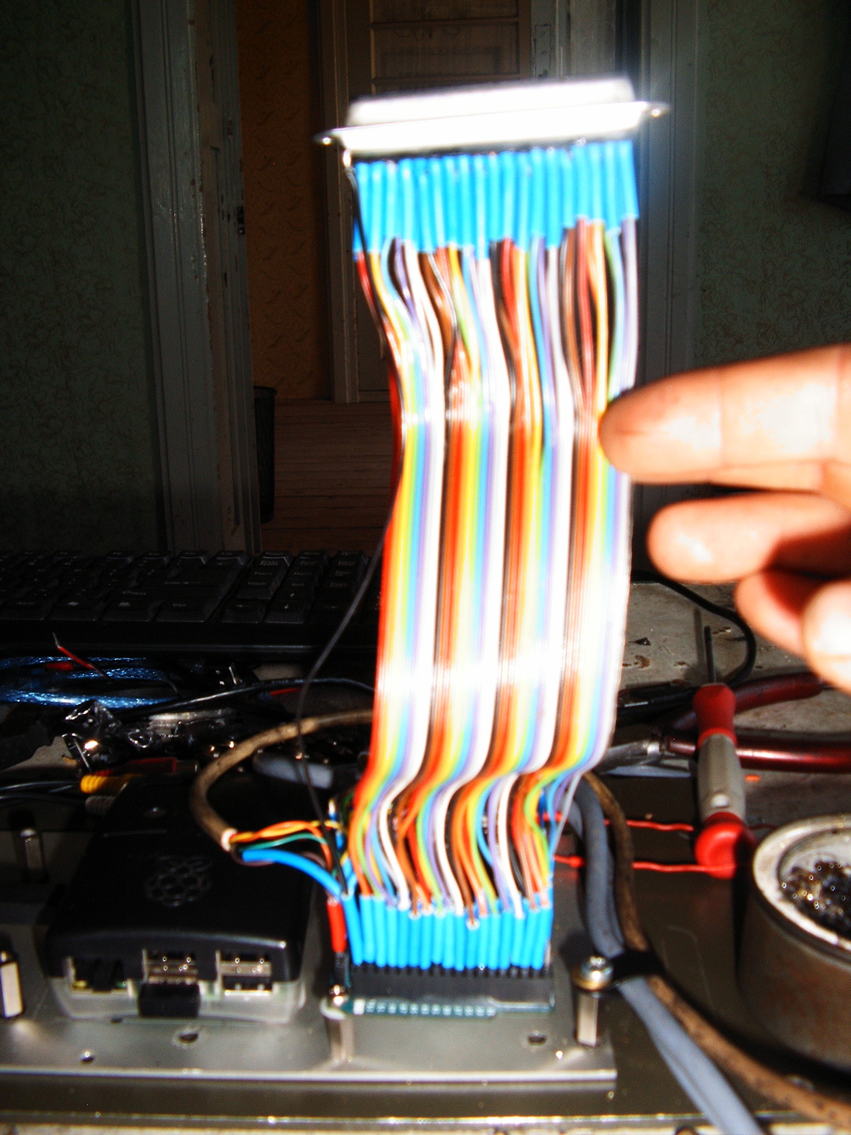
One hour later...
...Arduino ports 22....54 (sleepy, not remembering properly) are covered.
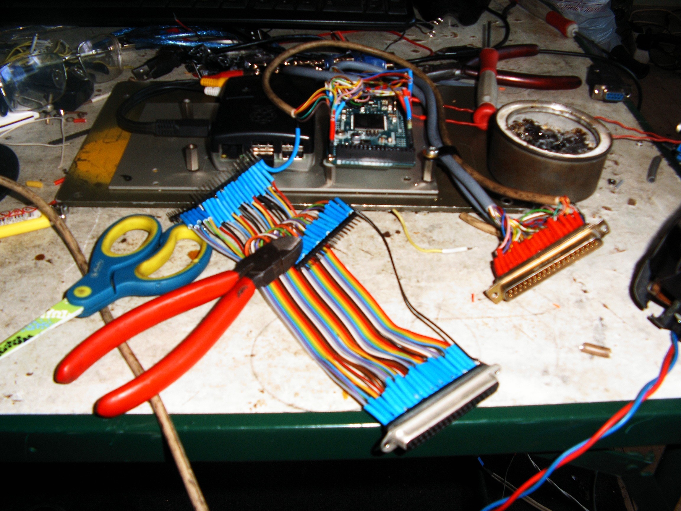
And this is the arduino to DB37F adapter.
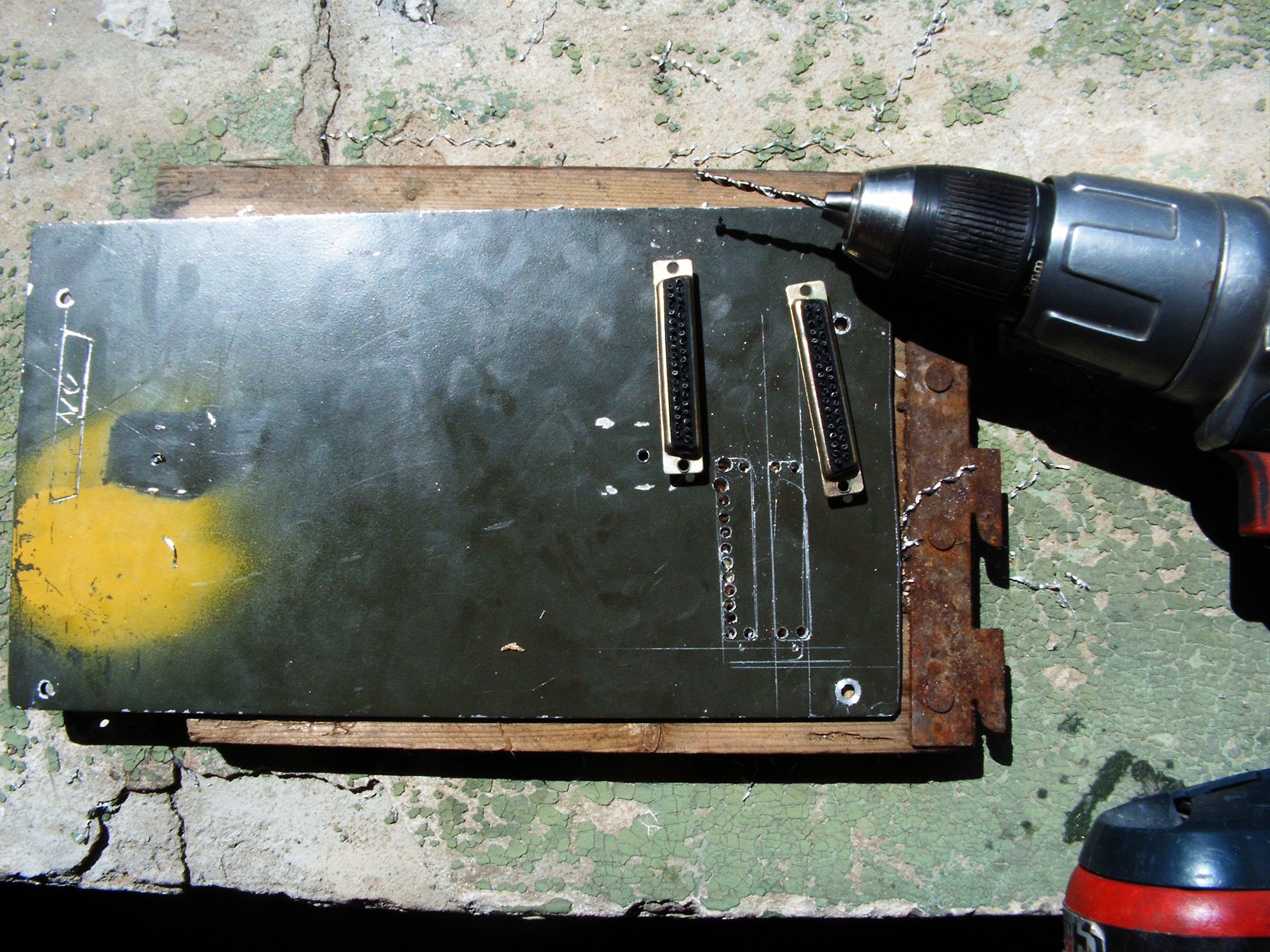
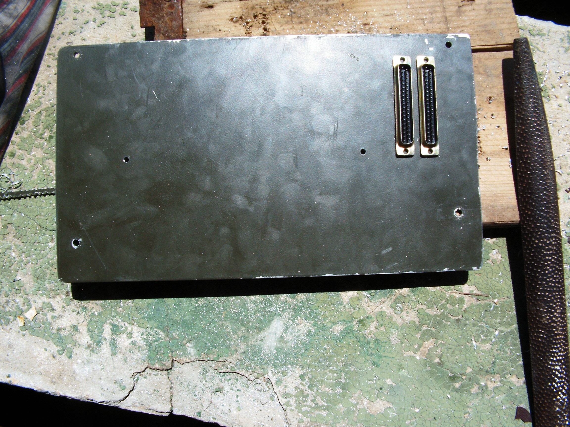
These two DB37 connectors are the Arduino's interface with the outside world. So let's drill some holes in the terminal casing.
Connectors are in their place. System ready for assembly. Need to cut the DB37 holes, then everything will go straight inside the car.
this is 5 millimeter thick aluminum sheet. My magic potions do not work in this case, just the patience.
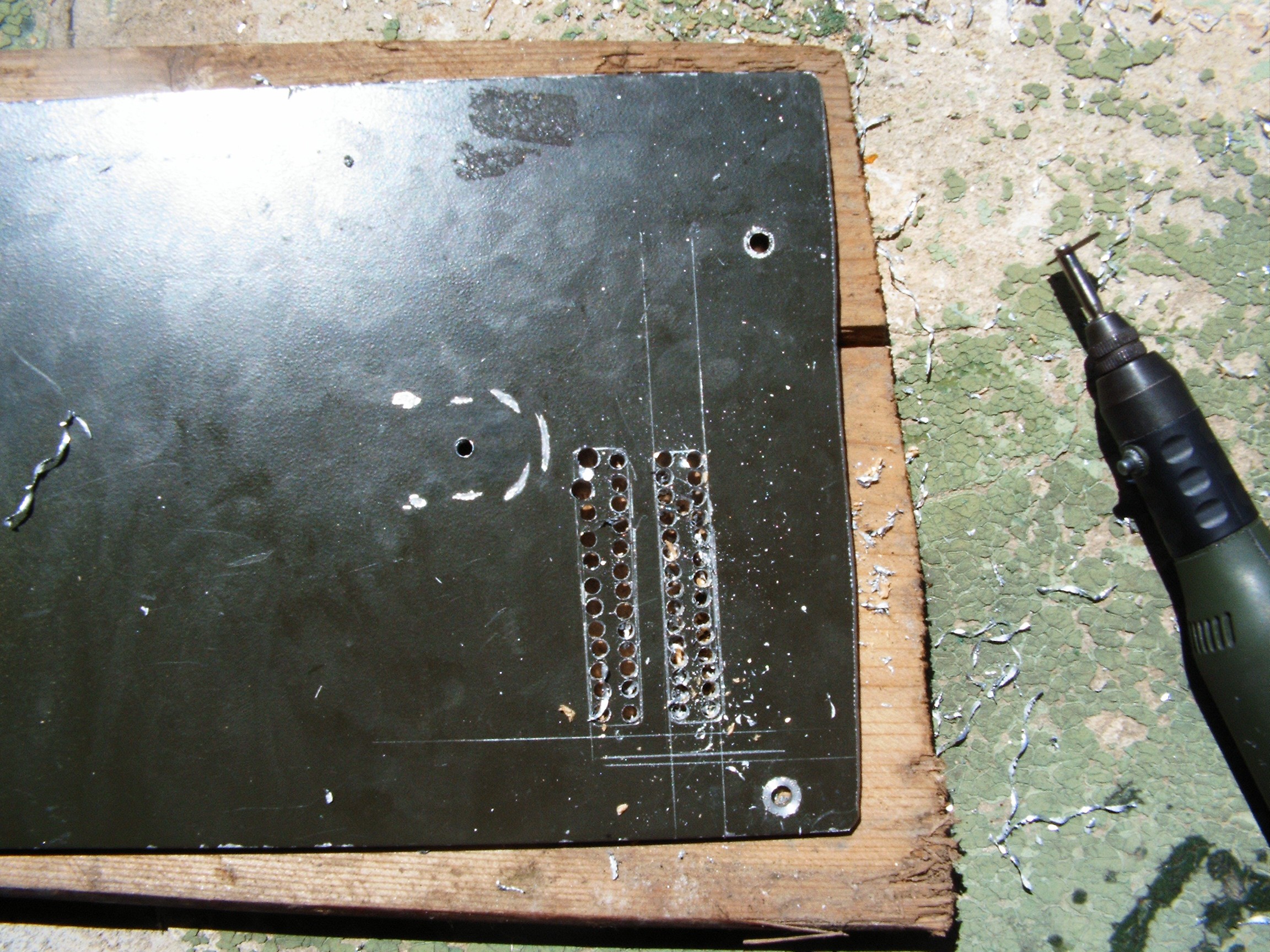
and many many ceramic disks.
Everything assembled while recharging the batteries for camera.
The thick white cable connects one of the DB37s from the terminal to the Junction Board on the console. For now there are two sensors connected: gasoline flow sensor and ambient light sensor. Everything else will be connected there through optocouplers or resistive dividers. Attention: arduino due accepts maximum 3.3V inputs.
For now the old gauges are connected. I still have to install all the warning lights.
Unfortunately I am unable to follow @Benchoff's suggestion - satellite navigation. NavIT should work but it does not compile under FreeBSD. And I am awayting for user name confirmation on their forum for almost a month - nobody bothered to answer.
Next log: rebuilding gauges and dials.
In the mean time, surprise!!!
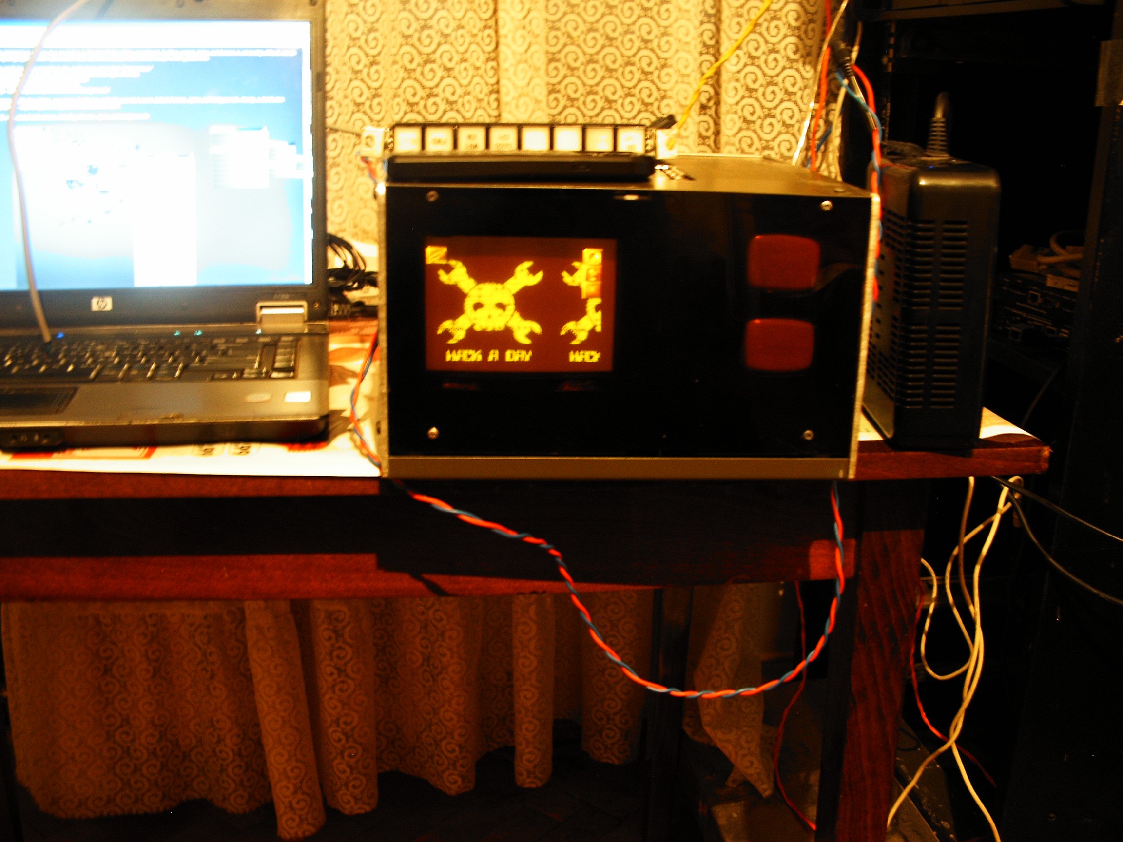
WindowMaker with HaD logo as background picture. The only image viewer I could find faster.
Next time when I open the terminal cover, I wish to display the HaD logo also on those two tiny oscilloscope CRTs.
Software is now work in progress. I only have a diagnosis table showing all the monitored parameters. Automobile diagram is desired, but I am still limited by FreeBSD capabilities and I'm not good at Linux.
[END OF TRANSMISSION]
______________________________________
kernel panic: improbability coefficient below zero
Discussions
Become a Hackaday.io Member
Create an account to leave a comment. Already have an account? Log In.
Obviously there isn't anything greater than an old missile programming terminal to use for this (even if it's made by decadent capitalists and therefore inferior, even if just morally)...
But just a little thoughtlet... If you needed multiple displays, and you're going with monochrome, might there be some potential to split the display 3 ways? As in separate R, G, B channels, one per monitor? So you could drive 3 monitors from one screen.
Main prob would be getting the signal out, the Pi offers composite and HDMI by default, as I understand. I think I've heard of somebody implementing VGA out though. Some inner functionality of the Broadcom chip not normally exploited on the Pi. They used a few resistors for a homemade DAC I think, was a HAD article.
So if you could do that, get a VGA signal out, you could perhaps split it 3 ways. Dunno if it would support 15KHz refresh, even if you tinkered with display registers. If there are any!
Anyway... just a thought! Besides that, there are a few AVR microcontroller-based terminal projects out there, perhaps one of those would do to drive extra screens? In text, part-bitmap, or even vector (yeah!) mode. Cos of course you need a few CRTs in there. Besides all the neon you're surely gonna use for indicators!
Or if not neon, you ever hear of those 7-segment / 14-segment displays that used tungsten filaments? Like old incandescent light bulbs, but arranged as segments. Called Numitron, maybe? They might be good. Certainly using just the small, simple, bulbs as indicators, since there must still be thousands of those lying around the world.
Are you sure? yes | no
Don't know man... not getting enough likes and attention to motivate such a deep work....
Are you sure? yes | no