0%
0%
Patrick
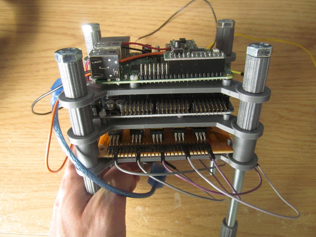
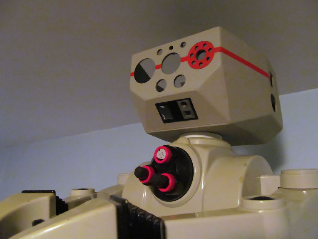
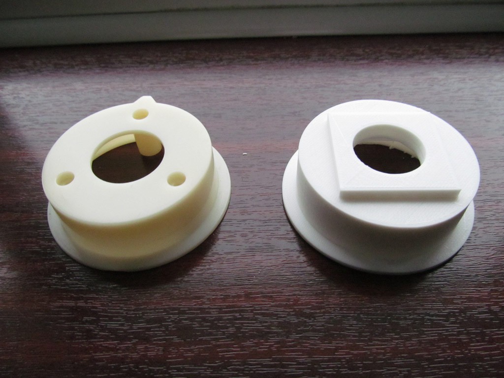
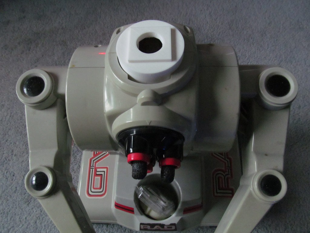
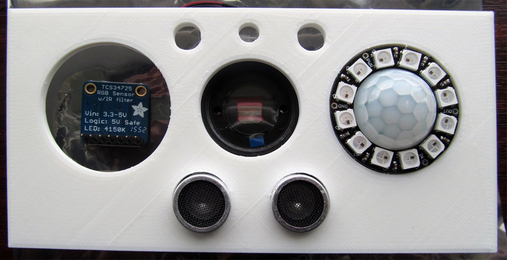
RAD v1.0 robot + Raspberry Pi + gadgets = ???
Become a Hackaday.io member
Already have an account? Log in.
Just one more thing
To make the experience fit your profile, pick a username and tell us what interests you.
Pick an awesome username
hackaday.io/
Your profile's URL: hackaday.io/username. Max 25 alphanumeric characters.
Pick a few interests
Projects that share your interests
People that share your interests

 Matthew H
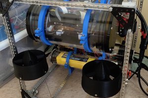
 Tim Wilkinson
 Stephen Chasey
 UCTRONICS
I see a bug here... your robot does not look like a less-than-intelligent anthropomorphic pink sea star. That's a major issue!