 Yann Guidon / YGDES
This is the "neovintage" version of #Yet Another (Discrete) Clock using original old parts as much as possible "for research purpose".
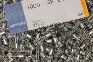
I (@Yann Guidon / YGDES) receive help from two contributors who have more experience with Germanium than me: @Alexander Shabarshin and @jaromir.sukuba. This is invaluable to decypher russian parts and cyrillic data sheets or circuits, thank you guys ! Alexander writes some of the logs, and he also started his own germanium clock project using circuits we develop here.
Expect power consumption to be higher than the MOSFET version, but fortunately, the invention of the transfer resistor is saving us the insane amounts needed to power the heating elements of vacuum tubes. Relays don't need high voltages either ;-)
Some design constraints
- old/vintage parts wherever possible and whenever available
- 4.5V power supply from alkaline batteries (so power consumption should be kept low and supply varies between 4V and 5V))
- PNP Germanium transistors is the major type, though NPN is really required at some places
- Low frequency Crystal oscillator as discrete clock source (I got down to 2500 cycles/s !)
Structure
The clock is made of a similar design as the #Yet Another (Discrete) Clock but the technology is a bit different so one single module will not fit all. We mostly need
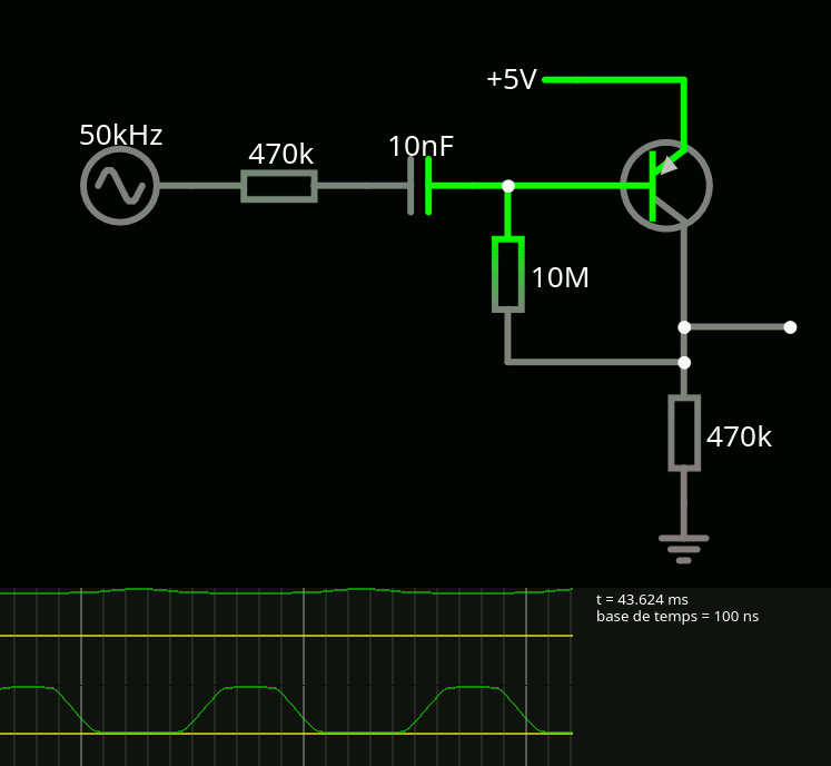
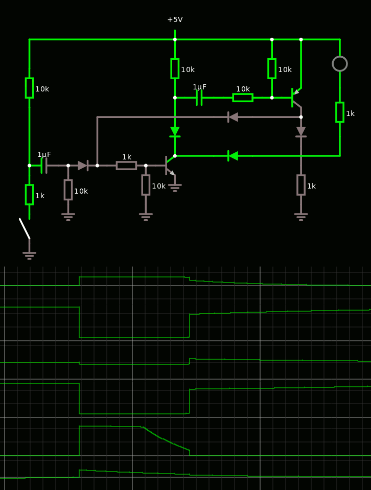
- Divide-by-two cell for the frequency divider (similar to
![]() )
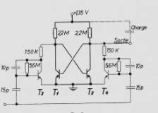
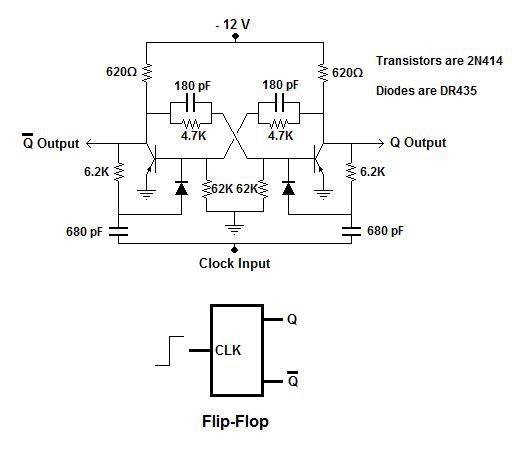
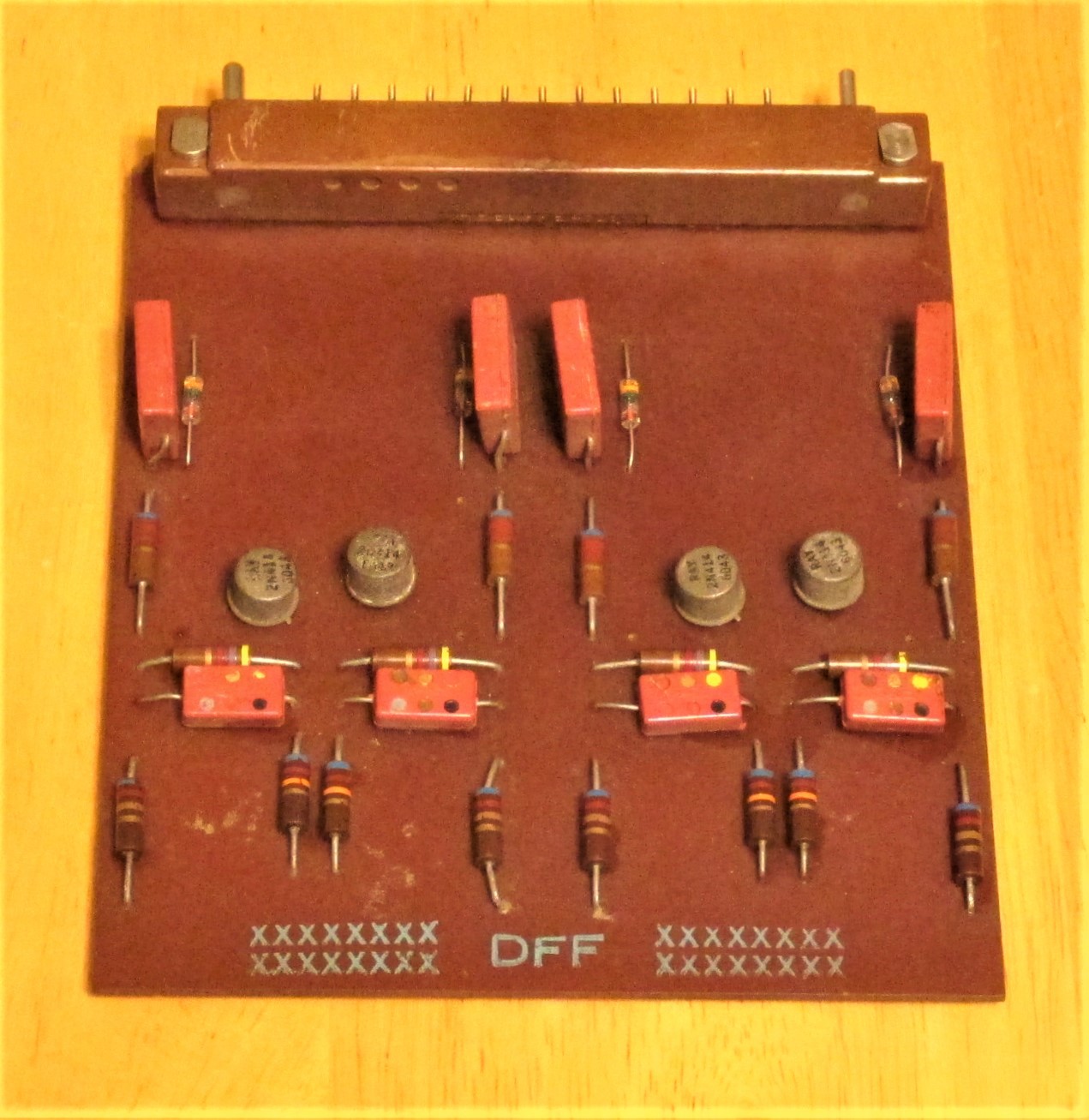
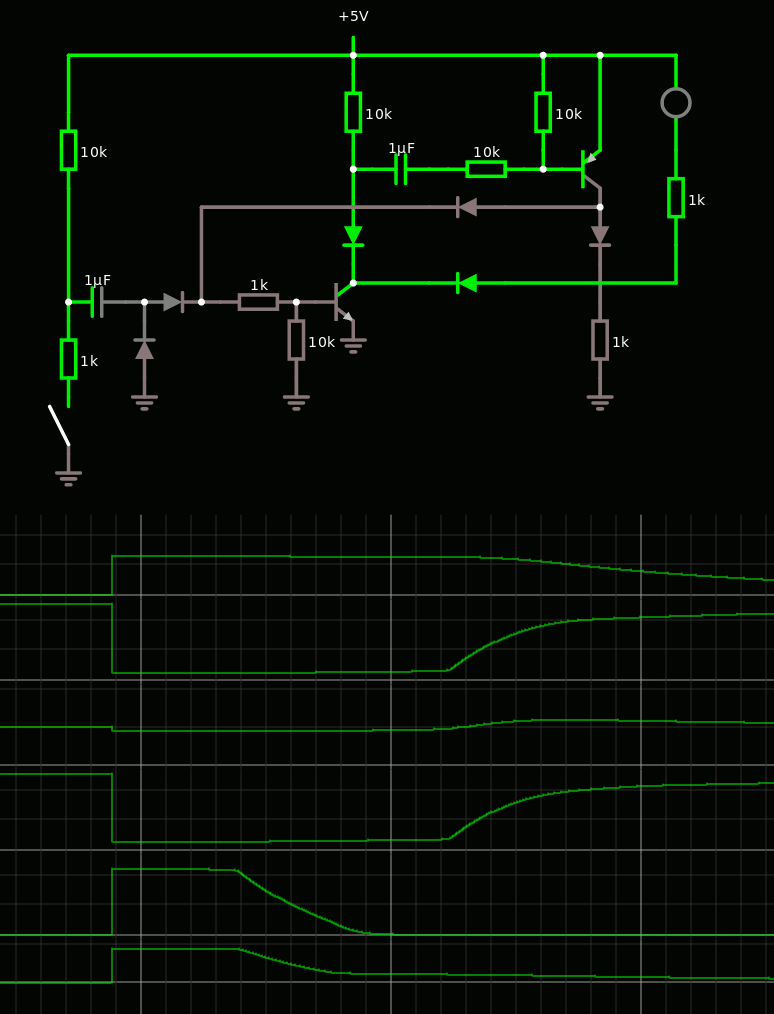
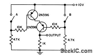
) - Flip-flop cell for the Johnson counters (2, 3 and 5 stages). No schematic defined/found yet but it might be adapted from the 4-T of this 50 years old circuit:
![]()

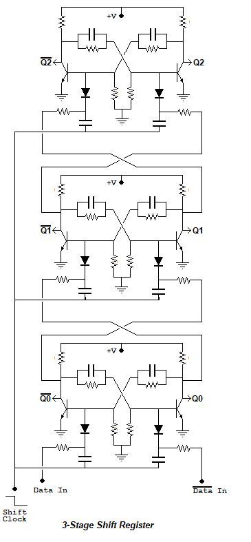
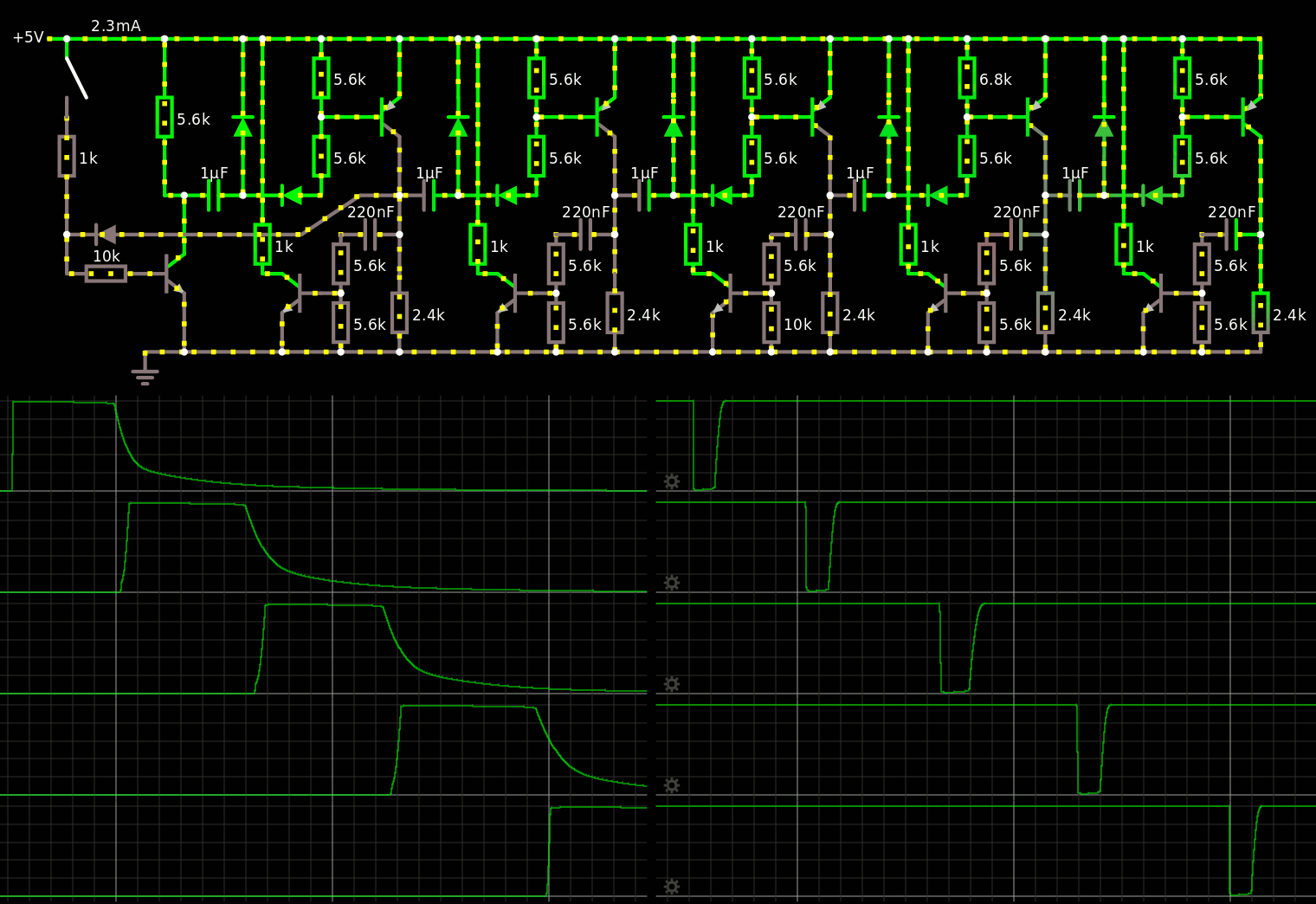
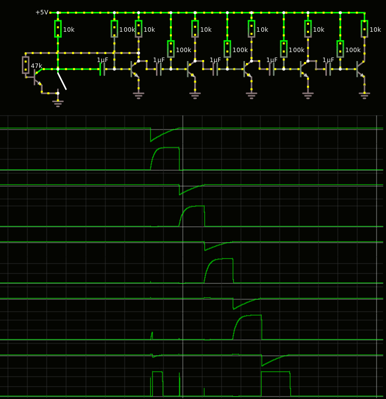
The Johnson counters directly drive the LEDs:
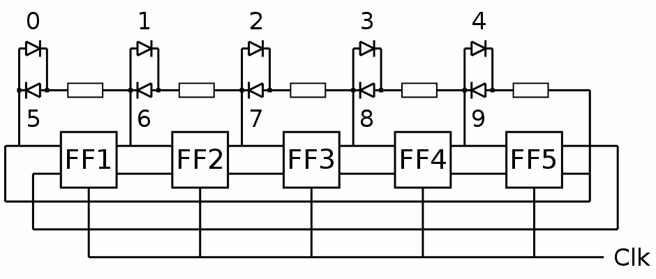
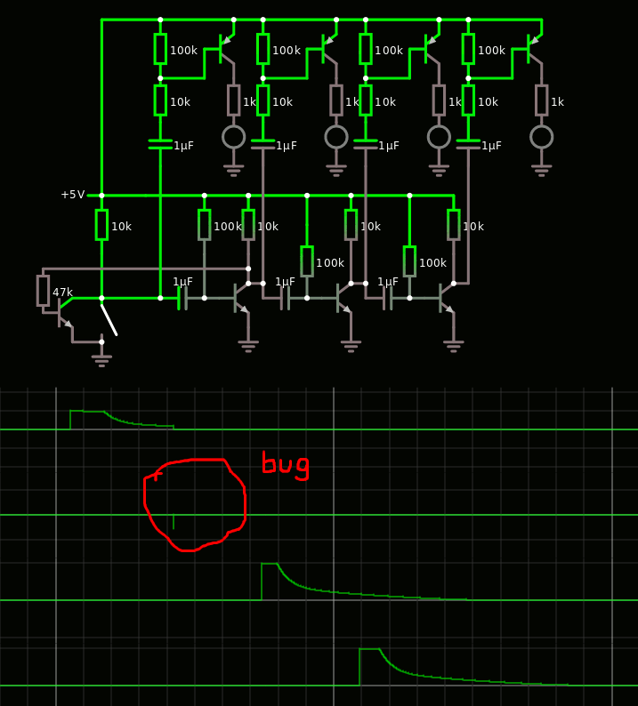
This diagram must be corrected because it works well for MOSFETs but Ge BJTs behave differently, the previous sentence means "there is no 7-segments decoder".
Clock:
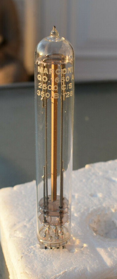
The chosen clock source is a 18KHz quartz resonator in a glass tube. Others, slower, are considered, depending on availability. Total: 39 FlipFlops (the initial estimate).
Logs:
1. 1st approach
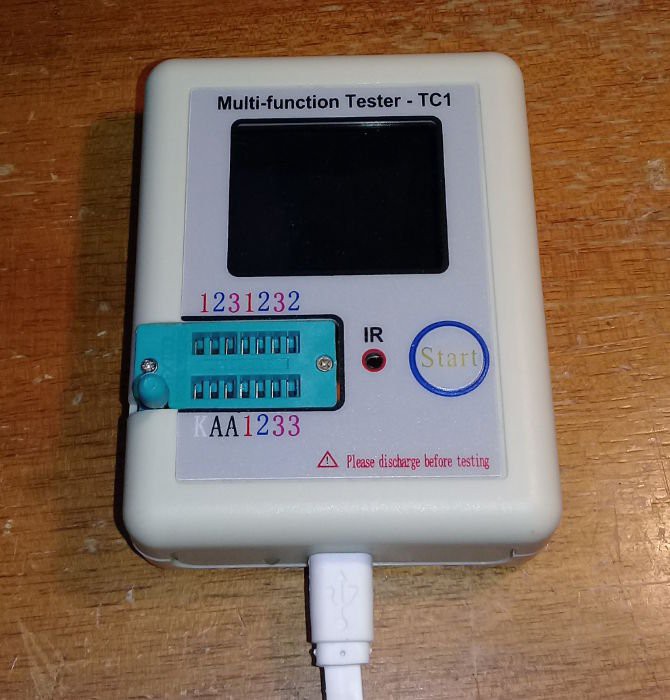
2. Testing Germanium transistors
3. Crystal oscillator
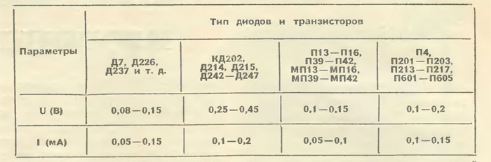
4. Germanium diodes
5. 2nd approach
6. Testing Germanium transistors (2nd part)
7. Crystal Oscillator (Germanium Edition)
8. Triggering Germanium
9. Vintage transistor book
10. Got Quartz !
11. Reverse-engineering vintage quartz resonators
12. It just works
13. More ingredients to cook germanium
14. PCB received
15. New inventory
16. Easier frequency division
17. Another interesting BJT DFF circuit
18. More bistables
19. Even more bistables !
20. Even more bistables: plot twist !
21. More bistables...
22. I don't know why it works
23. D-FF without metastability
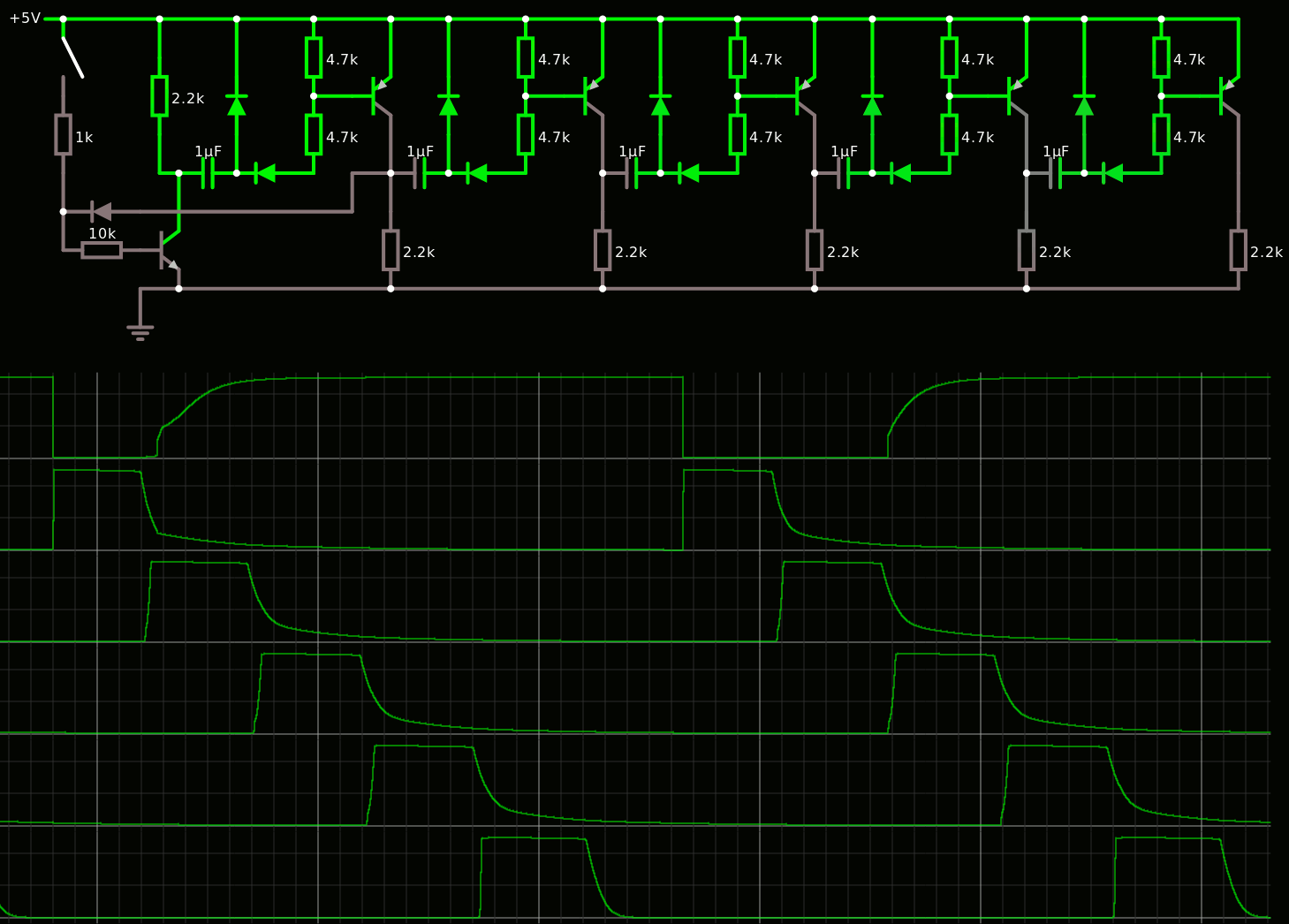
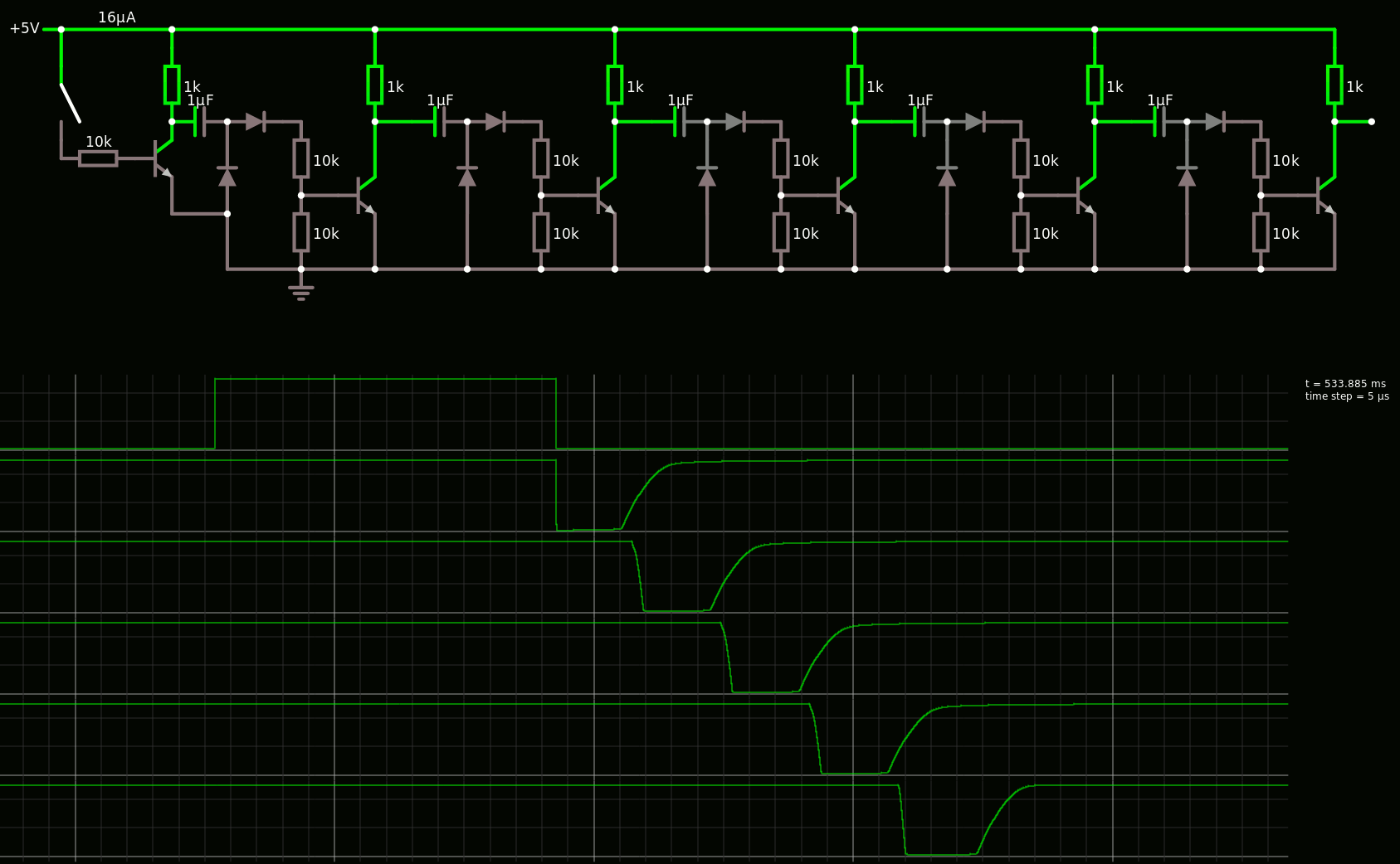
24. First shift register
25. Germanium is not for ever...
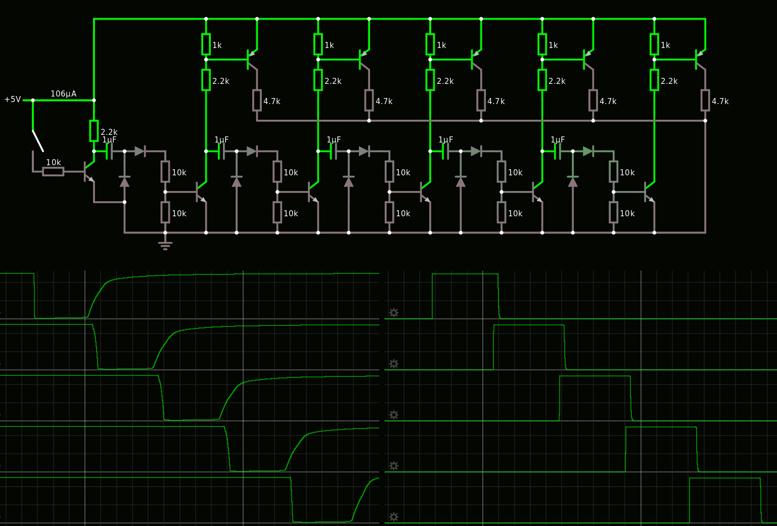
26. Towards a smaller shift register
27. Pulser-sequencer
28. Reduction by mirroring
29. Germanium lemonade
30. More inspiration
31. More Germanium lemonade, OC70 edition
32. Working bistable at last !
33. Funny clock preamp
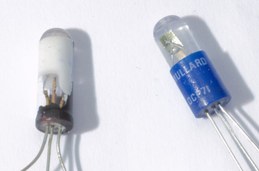
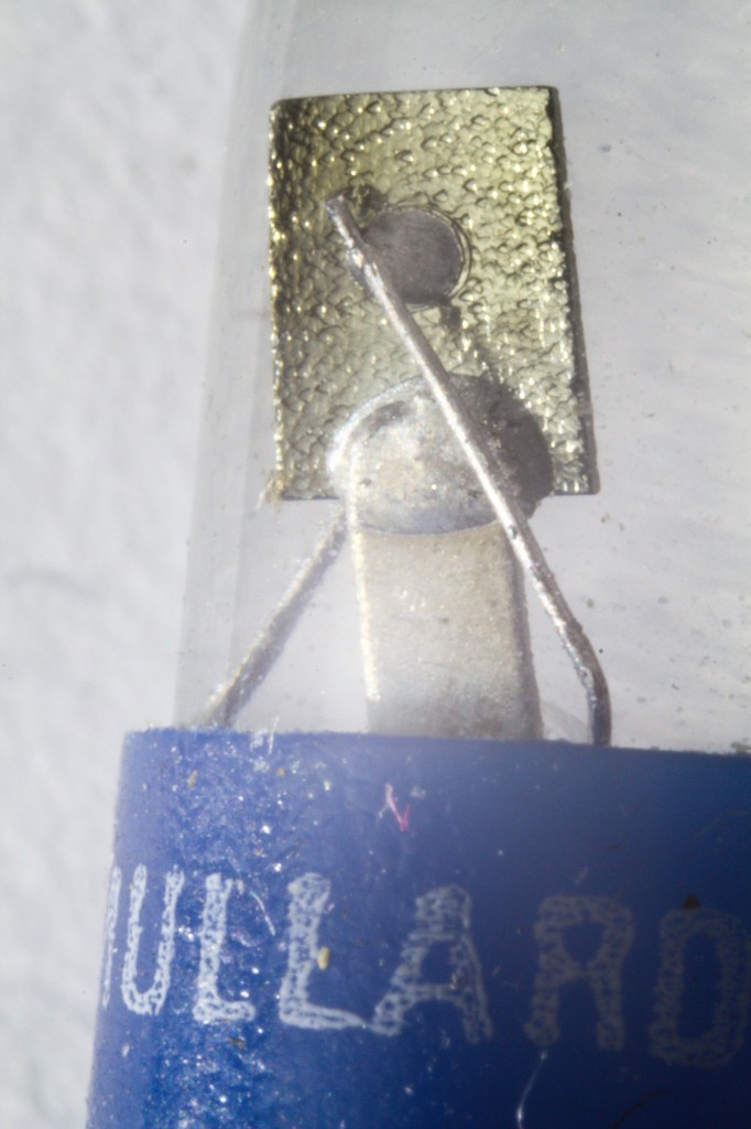
34. Inside OC70
35. Clock preamp 3T
.
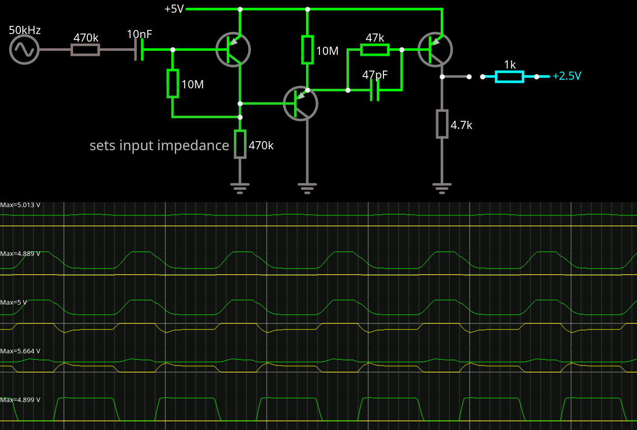
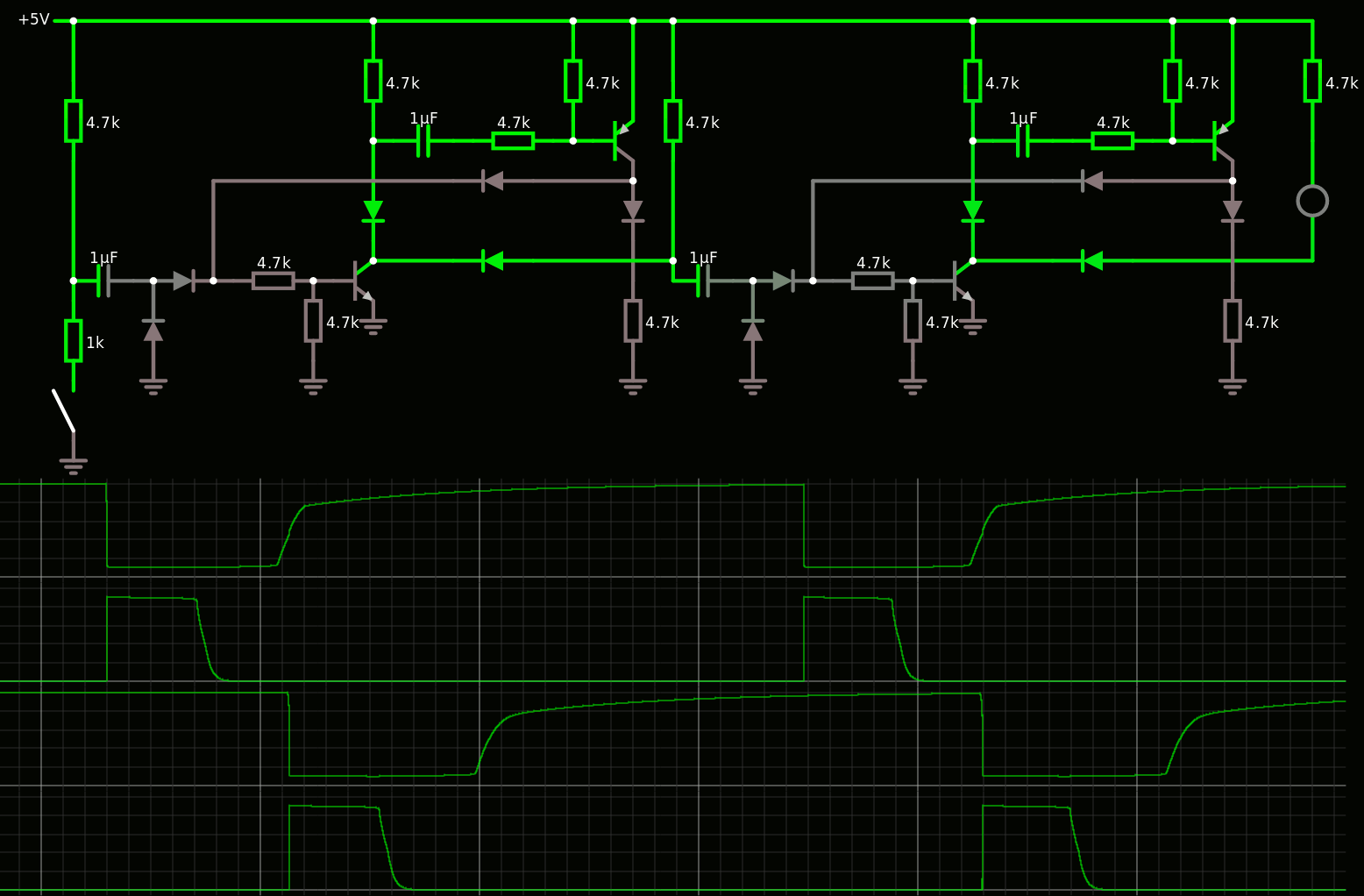

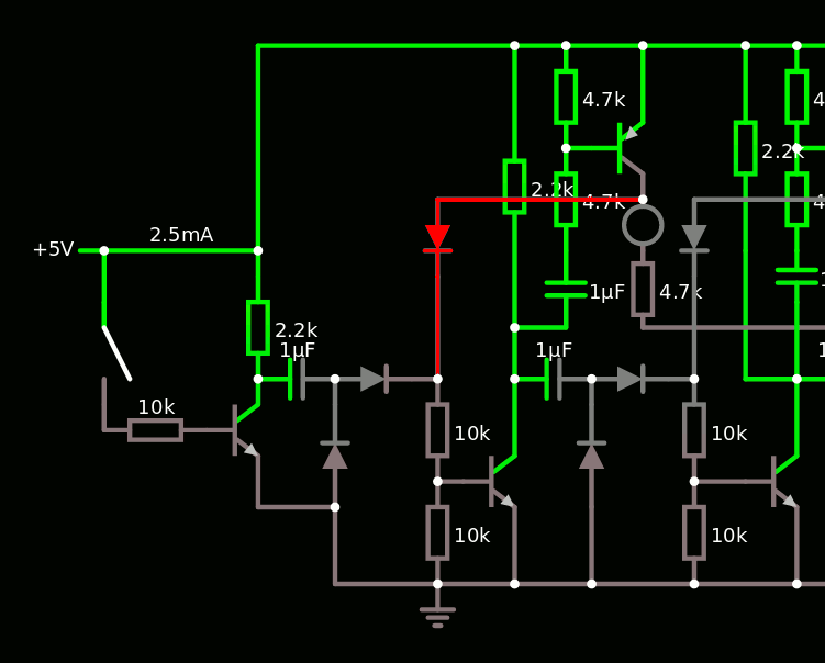
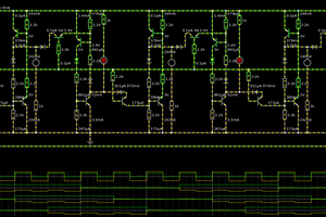
 Sometime it wants to find crazy negative voltages at the collectors of the PNPs. I'll have to test it on the bench but it looks promising.


 Ted Yapo
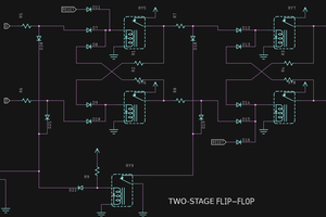
Well, let me add some ideas :)
While i studied "yet another discrete clock" project (very neat D-type flip-flops and Johnson counters), i must admit that binary logic is best in that it is very reliable and tolerates components drift but at cost of complexity.
Is actually binary a must? Why not to have "analog" appliance, at least it will be an unusual approach.
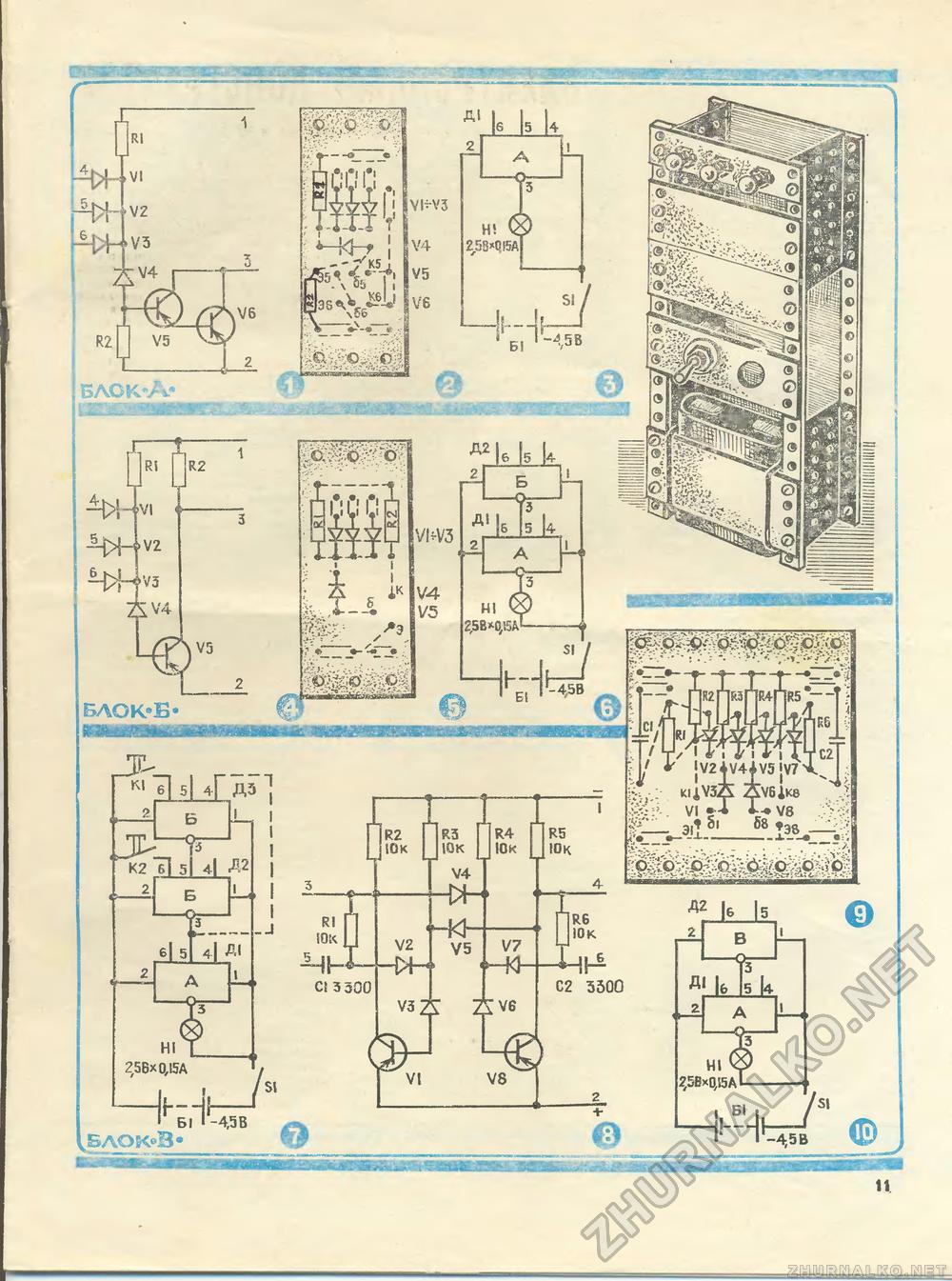
This is schematic of divider (from book described supposedly tested designs of amateur builders):
There are oscillator and two stages of divide by 10. It says that each stage can divide by max 7 with ferrite cores, and by max 13 with now obsolete Al-Si-Fe cores (huge 36 mm diameter, low mu, low frequency, high flux. I believe modern iron powder might go just as fine). First coil is 0,33 Henry and next 3,3 Henry. Of course main disadvantages are complicated adjusting tank freq. and need for thermal stability of LC tanks (i believe 2,5% or better in whole temperature range ). Pobably need for careful temp compensation?
Then, simple ring counter that drives LEDs, no binary D flip flops. More ring stages but much simplier each stage. Schematic from somewhere:
I am so sorry to show schematics that i did not try myself, so please forgive if these have some flaws. :)