 David Spinden
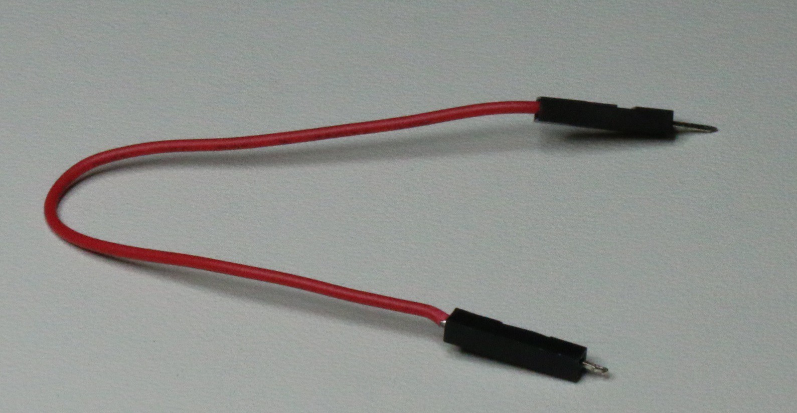
ViaConnects plug directly into plated vias that are sized for 0.1” headers. It’s like a “Dupont” jumper wire, but for boards that don't have headers. It works by conductive fingers making contact inside the barrel of a via.
Project Goals:
*Removable, temporary [goal met]
*Eliminates the need to solder [goal met]
*Connection to standard .1" spaced vias [goal met]
*Causes little or no damage to the via [goal met, multiple mates did not show
any difference in the via copper pillar under a 20X scope]
*Easily producible [very achievable as contacts used are already in production]
*20MHz frequency at min. [goal met with passing a 20MHz sine wave through the
pin]
*100mA min. current capability [goal met. Additionally, the datasheet states 2
Amps!]
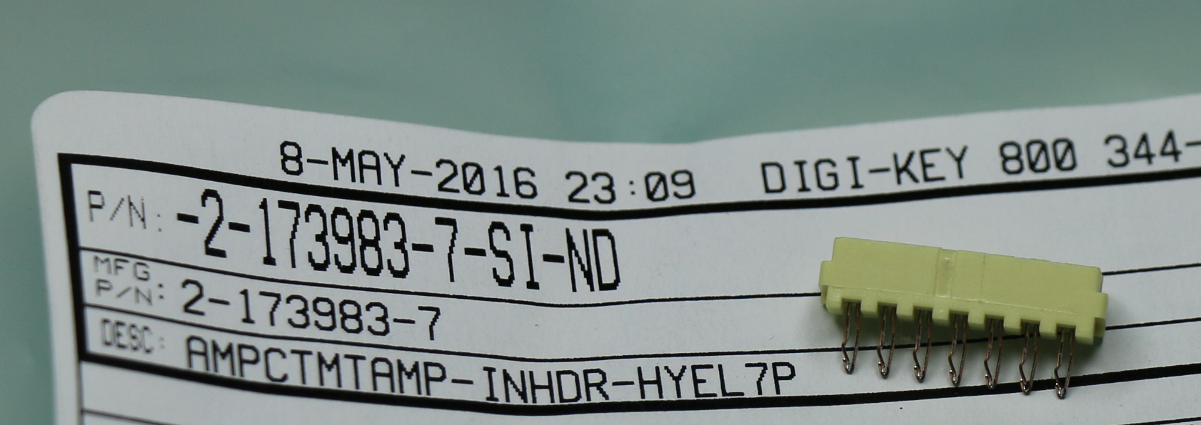
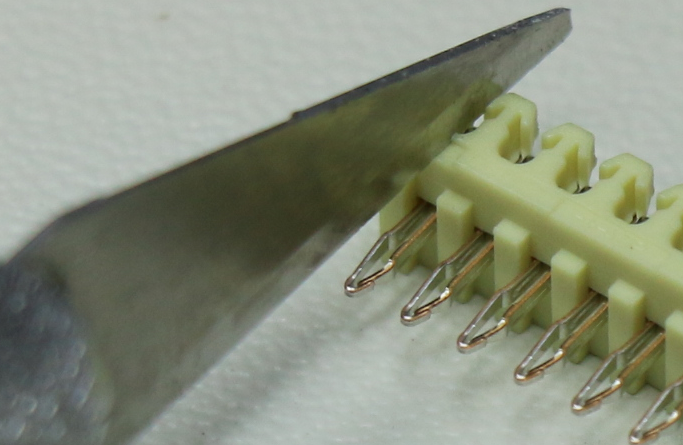
The original CAD files are located here: https://github.com/SpinInven/ViaConnect. The instructions to build a working prototype are below. The contact used is detailed here with a 3D model: http://www.te.com/usa-en/product-2-173983-7.html.
In the movie "Hudsucker Proxy," the lead character Norville Barnes draws a circle on paper and says “You know, for kids.” Like Barnes’ hula hoop, sometimes something that should be obvious just needs to get the right attention. The ViaConnect is a great tool for any electronics toolbox. It fills a true gap; I don't know of anything else that accomplishes the same goal.
I hope you find it useful and use it for your next hack!


 , I assume it is against soem rule or another.


 Matthew McCardle
 Sean Hodgins
 SUF
SUF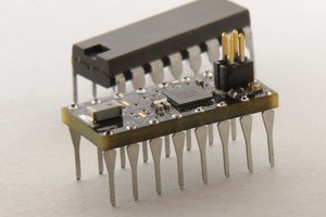
 Philip
So much better than a header because you can see exactly where your pin is connected to instead of trying to line up rows of black voids with the silk print below from a funny angle in dim lighting. Please make millions.