 amelia.you
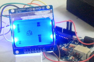
Hooking up a Nextion LCD to an Arduino UNO
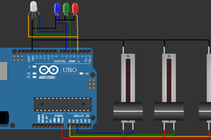
- Connect +5V to 5V on the Arduino
- Connect TX to pin 2 on the Arduino
- Connect RX to pin 3 on the Arduino
- Connect GND to GND on the Arduino
This is a Nextion LCD Touchscreen Tutorial for Arduino.
Already have an account? Log in.
To make the experience fit your profile, pick a username and tell us what interests you.
For this first part of the tutorial we are going to be using a firmware that demonstrates a couple of buttons, a progress bar and a text field.
Press the check boxes and note how the boxes give feedback when they are being pressed. They still do not change to Selected because we haven't sent the command to do so yet.

Initial view of example screen
The .HMI file is included in the firmware folder.
Relevant data to note when looking at the .hmi example file.
The Pressed image configured to 1 is why the check boxes show the round grey circle when they are being pressed even though we haven't configured anything in the Arduino yet.
Upload the "ReceiveMessages.ino" sketch from nextion/examples and open the Serial Monitor. Try pressing and releasing the two checkboxes. The responses should appear in the monitor. Note that the messages only appear after releasing the buttons. The exact behaviour is configured in the relevant Touch Event tab in the editor.

Button press (release) messages
Using the listen() function any message coming from the Nextion is stored in a String.
void loop() {
String message = myNextion.listen(); //check for message
if (message != "") { // if a message is received...
Serial.println(message); //...print it out
}
}
We can modify the loop() to detect when a button is pressed (or in this case - released). Update the loop() with the following code:
void loop() {
String message = myNextion.listen(); //check for message
if (message != "") { // if a message is received...
Serial.println(message); //...print it out
}
if (message == "65 0 2 0 ffff ffff ffff") {
Serial.println("Pressed Checkbox 1!");
}
}
The "65 0 2 0 ffff ffff ffff" was copy/pasted from the Serial Monitor. What does the message mean? Here is the official Nextion Instruction Set and a breakdown of the message:
This can be read as: "Button 1 on Page 0 was released". But it's easy to just copy the message and compare was done in the code above.
Making the button turn on
The next step is to update the icon when the button is pressed. In the code below instead of printing to the serial monitor we are sending two commands:
We send these commands to the Nextion using the sendCommand() function:
void loop() {
String message = myNextion.listen(); //check for message
if (message == "65 0 2 0 ffff ffff ffff") { //if button "b0" is Released
myNextion.sendCommand("b0.picc=2"); //set "b0" image to 2
myNextion.sendCommand("ref b0"); //refresh
}
}
Now, if everything went well when the first button is pressed and released the green checkbox is turned on! It won't turn off because we haven't told it to. What would be the commands to turn the button Off?
"b0.picc=0" and then "ref b0". This switches the image behind the first button back to 0.
Toggle ButtonToggling buttons on and off are a common occurrence in controls so we decided to add a function called buttonToggle(). Upload the "ToggleButton.ino" example and test the buttons. They should now switch between Checked and Unchecked.
buttonToggle(button state boolean variable, component name, default picture ID, selected picture ID)
To use the buttonToggle function a boolean variable is created for each button:
boolean button1State;
boolean button2State;
In the loop() we listen for a message, test for the correct button press and execute the function:
void loop() {
String message = myNextion.listen(); //check for message
if (message == "65 0 2 0 ffff ffff ffff") {
myNextion.buttonToggle(button1State, "b0", 0, 2);
}
if (message == "65 0 3 0 ffff ffff ffff") {
myNextion.buttonToggle(button2State, "b1", 0, 2);
}
}
Update Text
Upload the "UpdateText.ino" example to your Arduino. The text field in the Sensors card should be flashing between "Hello" and "1234".
setComponentText(component name, String)
In the loop() are two examples of how to send text to a text area.
void loop() {
myNextion.setComponentText("t0", "Hello");
delay(1000);
int value = 1234;
myNextion.setComponentText("t0", String(value));
delay(1000);
}
Updating a Progress Bar
In the Nextion Editor there is a component called a Progress bar. There are several aspects that I don't like about the implementation. First, it requires that one isolates the graphics for an empty and full progress bar and then add them to the Pictures in the Editor. Secondly, every time the progress bar receives a new value it erases the progress bar entirely and then repaints it. This causes a noticeable flicker even if it repaints with the same value. Hopefully, this will be fixed in the future.
Using the following technique, creating the graphics is a lot simpler. There is no flicker. And the technique can be used in a variety of creative ways.
The Graphics and Image Cropping (why it's so cool)
The three screens below are the ONLY graphical assets that were used in this project. Each screen is only between 17 and 19 kilobytes. Even the temperature progress bar states are included here. The first screen has all the graphics in their default or OFF states. The second displays both the buttons in their Pressed state. And in the third the buttons are shown in their Selected State and the progress bar is completely filled. How can this be? What if I want one button ON and the other OFF? How do I set the progress bar to 50%?
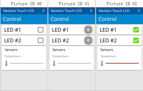
The trick is to use a technique called image cropping. Certain components, such as buttons, can allow a specified area of another screen to show through. So, for button 1 to show the green selected icon just allow the image from Picture ID #2 to be displayed only around the area of the button. To make the temperature sensor show 50% red, allow half the progress bar of Picture ID #2 to display.
The direct command to display a portion of a picture is "picq" which exposes a section of a picture at coordinates x,y with a certain width and height.
"picq x,y,w,h,picid"
x: x coordinate starting point;
y: y coordinate starting point;
w: Region width;
h: Region height;
picid: Picture ID;
This can be done manually using the sendCommand() function or by using the updateProgressBar() function.
updateProgressBar(x , y, width, height, value, empty picture ID, full picture ID)
The value to be displayed should be scaled between 0 and 100. This can be done easily with the map() function.
In order to "wipe" the progress bar we will need to its x,y position and it's width and height. A quick and easy method is to use Add Component-->Progress bar to create a temporary component. Move and stretch the component over your progress bar and write down the values x,y,w,h. Then Delete Component-->Delete Selected Component to erase the component.
The values I have for the progress bar are: 56, 321, 195, 8
Upload the "UpdateProgressBar.ino" sketch to the Arduino. This sketch monitors analog port 0 and displays the values on the progress bar and the text area. To test I connected a potentiometer to 5V and GND with the wiper connected to pin A0.
void loop() {
int sensor = analogRead(A0);
if (abs(sensor - old_sensor_value) > 20) {
old_sensor_value = sensor;
int scaled_value = map(sensor, 0, 1023, 0, 100); // always map value from 0 to 100
myNextion.updateProgressBar(x,y,width,height,scaled_value,0,2); // update the progress bar
myNextion.setComponentText("t0", String(sensor)); // update text using original sensor value
}
delay(100);
}
Upload the "AllTogether.ino" sketch. The buttons should toggle, the progress bar should update and the text field should display the value of A0.

If you're going to copy someone else's work, you should at least give them credit for it. http://openhardware.gridshield.net/home/nextion-lcd-getting-started-for-arduino
 huy
huy
 Open Technology
 Misfittech
Видео на Ютубе оставляет желать лучшего !!! А описание кода заслуживает внимания !!!