 danjovic
The firmware for Guri deeply relies on interruptions to work. Today I've started to test this mechanism. Basically an input generated by the RPM sensor (points/hall sensor) is used to trigger the external interrupt which clears the Timer 1 and program two output compare values being one to turn on a power transistor and charge the coil and another for turning off the transistor thus interrupting the coil current and generating a spark.
There are at least two conditions that should be cared of:
1. The engine speed is decreasing so fast that we reach the next revolution pulse before the time to the coil to turn off. As a failsafe for this condition the ext int code turns the coil off.
2. The engine stops but timer 1 is running and both compare outputs are programmed to generate interrupts. To deal with that situation the timer 1 overflow shuts the coil off, then stops the timer from counting and disable the compare interrupts. Both Timer1 and compare interrupts will be turned on again only in the next pulse from engine revolution sensor.
It is worth to mention that the when the first pulse from engine revolution sensor, either after powerup or after an overflow of timer 1 will be dismissed as with timer 1 stopped its value will be zero which is out of the valid RPM range for enabling the charging of the coil.
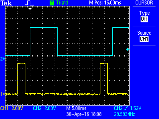
The capture below depicts the simulated engine revolution sensor in blue and the coil charging pulse in yellow. Assuming (for instance) that the coil needs 3ms to charge and the spark must occur 2ms before the TDC, the firmware measures the time taken from the previous turn and subtracts the amount of timer1 counts equivalent to 2ms and program compare output B. From this time it subtracts the amount of time equivalent to 3ms and program the compare output A.
Such timings can be seen in more detail on the capture below
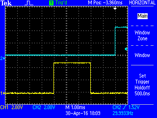
The rising edge of the blue trace represent the moment that the engine reaches the TDC.
2ms before that is where the yellow trace drops down to disable the power transistor and generate the spark.
3ms before the spark time (5ms before TDC) the yellow trace goes up to enable the power transitor to charge the coil.
The events have been described bacwards because this is how the firmware calculate the times: Bacwards from the estimated time of the next TDC.
Discussions
Become a Hackaday.io Member
Create an account to leave a comment. Already have an account? Log In.