 Karl S
As was almost suggested by a comment recently, I have added a PDF version of the schematics to GitHub.
And due to the same comment (thanks!), I have added a capacitor to the battery voltage sensing, which should solve any issue with the voltage divider impedance vs. the ADC source impedance.
In working on the PCB layout, I also decided that my universal SMD capacitor / resistor footprints (accepting anything from 0603 to 1210) were too big to be workable when it came to decoupling capacitors for the MCU. I also decided that it is unlikely for anyone to want to use sizes quite that big, so dropped the sizes a bit – now capacitors 1 uF and under are 0603 to 0805, and 10 uF capacitors are 0603 to 1206. Still got a lot of fun routing around the MCU to go though.
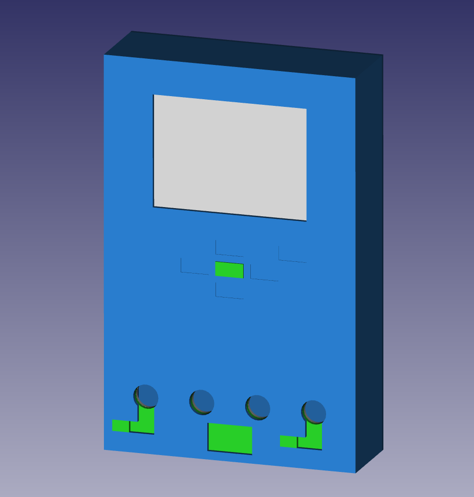 And the other noteworthy news is that I've updated the External Design CAD model – you can see a render on the right, although the colours won't end up like they are there.
I intend to make the case from FR4, as was suggested by a comment on my first external design project log (thanks!) and I learnt about from this Hackaday article. It won't all be soldered, epoxy will see significant use as well.
The green down the bottom is the USB port cover – slide it right to cover the terminals, and then up to uncover the USB port. This is necessary because I want USB for charging, and I'm not putting an isolated switching power supply in there.
Discussions
Become a Hackaday.io Member
Create an account to leave a comment. Already have an account? Log In.