Around two weeks ago I ordered all remaining pcb's and a lot of parts. They arrived just in time for some happy soldering in the days after Christmas. Each pcb was (sometimes partially) built and then it's main functions were tested, revealing soldering errors but also a few design errors. This is the state today (click it for bigger version):
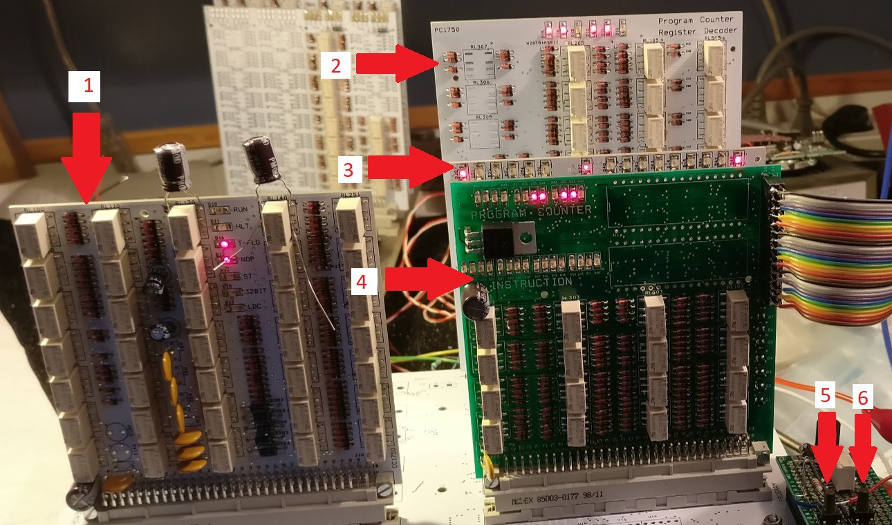
1) clock and control pcb
2) program counter pcb (6 bits)
3) instruction decoder pcb (only it's LED's are visible)
4) program memory and instruction register pcb
5) RUN button
6) STOP button
The pcb's are connected to the main pcb with DIN41612 connectors.
I started with the program memory and instruction decoder. (All pcb's in this project were intended to have a white color, but apparently I forgot to select the color when I uploaded the gerbers of this pcb). The flash memory itself is not yet assembled. There is a connector (where the ribbon cable connects) that is intended to connect to a flash memory programmer. It is now connected to 16 pushbuttons, to control the contents of the instruction register manually. The instruction register worked (but several of the 2K2 resistors in the hold circuits had to be lowered in value, apparently the current was not enough to keep the relays attracted).
Next was the clock and control pcb. The clock circuit did not work as expected and had to be modified. Two 100uF elco's (visible on top of the pcb) set the clock to approx. 5 instructions per second, slow enough to have a sense of what is going on during testing. Asymmetry in the clock signal will have to be solved (and higher speed will be set at a later time). One of the board's input signals was not connected, a wire was needed to correct this. Another problem: The single-step button should start executing one instruction and then stop. Unfortunately, the stop function works too well, so much that pressing the single step a second time does not run a next instruction...
The program counter pcb also has decoders for reading and writing to the registers. Only the program counter section was mounted for now. After re-soldering a resistor, I started the clock and watched the PC counting... 0, 1, 2, 4, 8, 16 .... Oh what's wrong ? Did I build a shift register instead of a counter ? After following the signals on several wires, it occurred to me. The PC has a master and a slave section, they each have a CLR signal. If one of the registers is not cleared, the bits stay 1 and you get this behaviour. This is not visible on the LED's if the leds are connected to the slave section and the non-cleared part is the master section. Well, the CLR of the master could be interrupted by relay RL341, and that was not placed because it was considered part of the decoder section. After placing RL341, it was happy counting !
Now the instruction decoder. It has led's that show the addressing mode ( Memory, Zero page, Immediate, register, test-and-branch) and the instruction ( LD, ADD, AND, OR, XOR ) and a few other output signals. This was simply tested by letting the clock run and manually put something in the instruction register. Many instructions could be tested this way. It revealed an error in the decoding for the DMPY instruction, were inputs to a diode gate had to be connected to IR_Y0 instead of IR_Y0_N. This diode gate was on the pcb with the instruction register, leading to a small modification there. For a LD instruction, also the OR led was on, could be corrected with an extra diode. The led for the PC was connected to a wrong point, not changed yet.
Some changes were made in the schematics and pcb design files before they were ordered, so the file section is no longer uptodate. One of the changes was another change in the instruction set... New instructions to subtract two registers without storing the result, providing compare instructions. Logic instructions (and, or, xor) were removed from the register mode and added to the zero-page mode. Documentation will be updated soon.
A good 2018 to all of you !
Discussions
Become a Hackaday.io Member
Create an account to leave a comment. Already have an account? Log In.
Cool! Glad to see turbo start of the assembly process.
Are you sure? yes | no
great looking design! looking forward to more updates and design details!
Are you sure? yes | no