 kirrent
In a sufficiently narrow conductor confinement of electrons leads to a certain number of allowed quantum channels. Much in the same manner as in conventional waveguides. Of course, unlike in a waveguide, electrons are subject to scattering events so if you want to see the effects of the quantisation a narrow conductor which is a lot shorter than the mean free path of the electrons. These extremely short conductors can be realised through the use of an STM probe, GaAs/AlGaAs heterostructures, or during conductance breaking events.
The conductance breaking events are the jankiest method but also the most possible to realise cheaply at home. It's pretty easy to set up a circuit where you can see the effect using a scope and a couple of gold wires. If you want something a bit more reliable and reproducible you can use a relay.
Still, no matter what you do the entire process is still pretty janky, so this first part of this project is to see how reliable the measurement can be made using only components that you might have on your own benches. This isn't as trivial as you might imagine. Sometimes there won't be any events, sometimes you might get heaps of noise because the electron transport isn't completely ballistic for some reason, sometimes there'll be multiple nanowires at the same time, and sometimes you'll only get the first level which for later purposes isn't enough.
Still, given a reliable and reasonably precise setup I want to see if I can use it to measure resistors. Given that you can measure multiples of the conductance quantum G0, which is nice and constant reference (indepedent of temperature, mechanical stress, and other factors that can affect resistors):
then you can account for an other pesky resistance in the circuit and even start to account for small non-linearities in whatever ADC you're using if the results are good enough.
 Inne
Inne
 Jonathan Newman
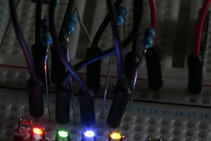
 ftregan
 Jeremy Gilbert