 SHAOS
SHAOSI built and tested both versions of educational TTL:
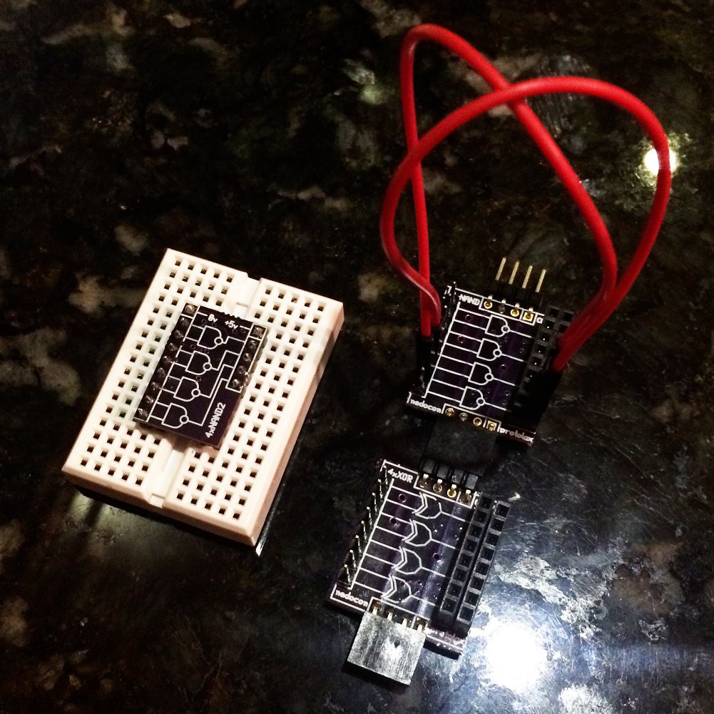
Unfortunately "no-breadboard" one has some outputs routed in wrong order :(
How breadboard one works is clear (I hope), but "no-breadboard" one needs some clarifications I believe - so as you can see inputs are male pin-header and outputs are female header receptacles - you should use special jumper wires where one end is female and another end - male. This way you never connect multiple outputs to the same input - it's simply not possible. So "no-breadboard" version is kind of breadboard by itself. Also on the top of every board you can see 4-pin header that is connected to bottom receptacle of other board - they bring ground (2 middle wires) and power (right wire) to every board. I imagine some kind of backplane on the top (top-plane?) where many columns of boards attached for power and ground.
I need some input from Hackaday community - which approach is better and should be elaborated deeper? Breadboard one or "No-breadboard" one?
P.S. I attached PCB source code for "breadboard" version and Gerbers for "no-breadboard" - as I said before it has ERRORS, SO USE IT ON YOUR OWN RISK!!! Link to OSHPark project for 1st breadboard version: https://oshpark.com/shared_projects/SWuqir41
Discussions
Become a Hackaday.io Member
Create an account to leave a comment. Already have an account? Log In.