 MobileWill
An OLED development board with 5-way navigation button in a small form factor for those that don't want to mess with designing their own hardware. Easy to use with the Arduino IDE or you can use Atmel Studio or your favorite environment that supports the Arduino Leonardo.
Hardware:
The design is based on my existing tool, the OLED Backpack for the USB Tester (a USB power measurement device). Most of the SUPEROLED8 is the same, minus the current sensing hardware and connections that attach to the USB Tester. In the second iteration I swapped the single button for a 5-way navigation button with a 2k resistor network to share a single analog pin. This saves four GPIOs for other uses. The unused GPIOs are broken out at the bottom and just below the micro USB connector. The UART is above the 5-way and I2C at the top left of the OLED display. Add-on hardware can be connected to the bottom to add more features, like sensors or various power options, for example. The PCB form factor is based on the Dangerous Prototypes Sick of Beige standard PCB sizes.
Firmware:
The demo code is a small 5x5 pixel filled square that you can move around with the joystick. The 5-way button is sampled via a single ADC and depending on the value, it is mapped to a button press. I’ve yet to work intensively on the firmware, but that is one of my current goals.


 JP Gleyzes
 minifig404
 Stefan Lochbrunner
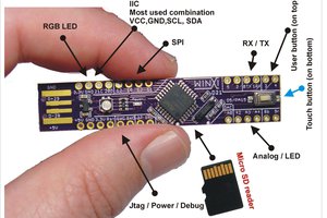
 bobricius
Cool! I just finished adding the first version of OLED support in Visuino :-) .
If you send me one, I can see to add support for the board in Visuino ;-) .