 Chuck Glasser
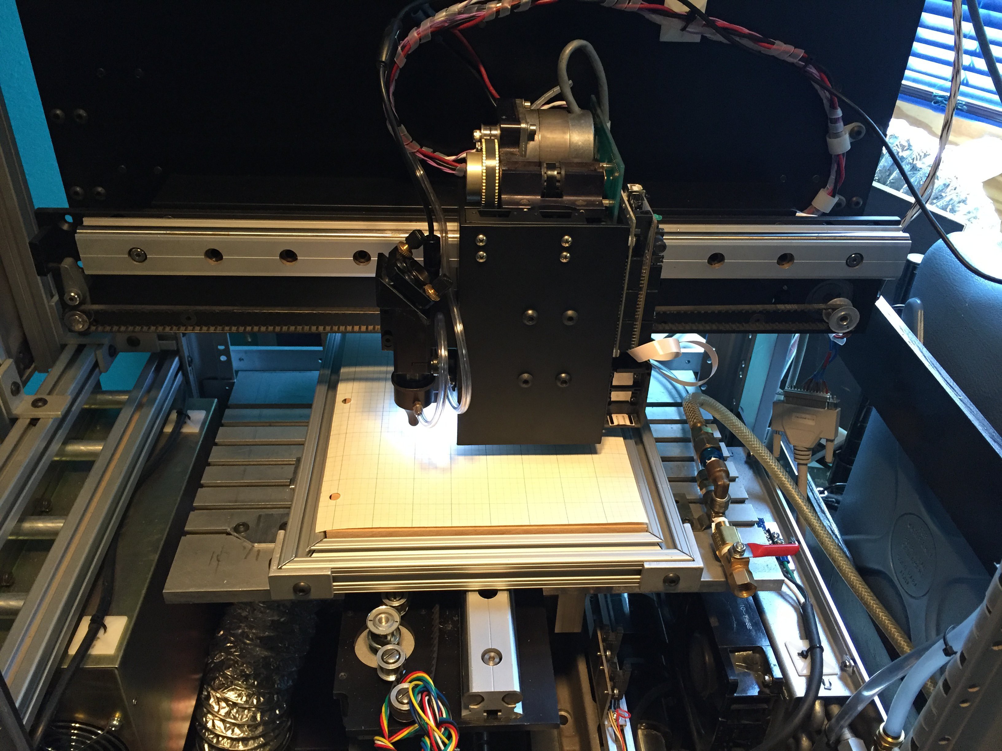
The original tool head was encroaching on the working space of the Long Bed below.
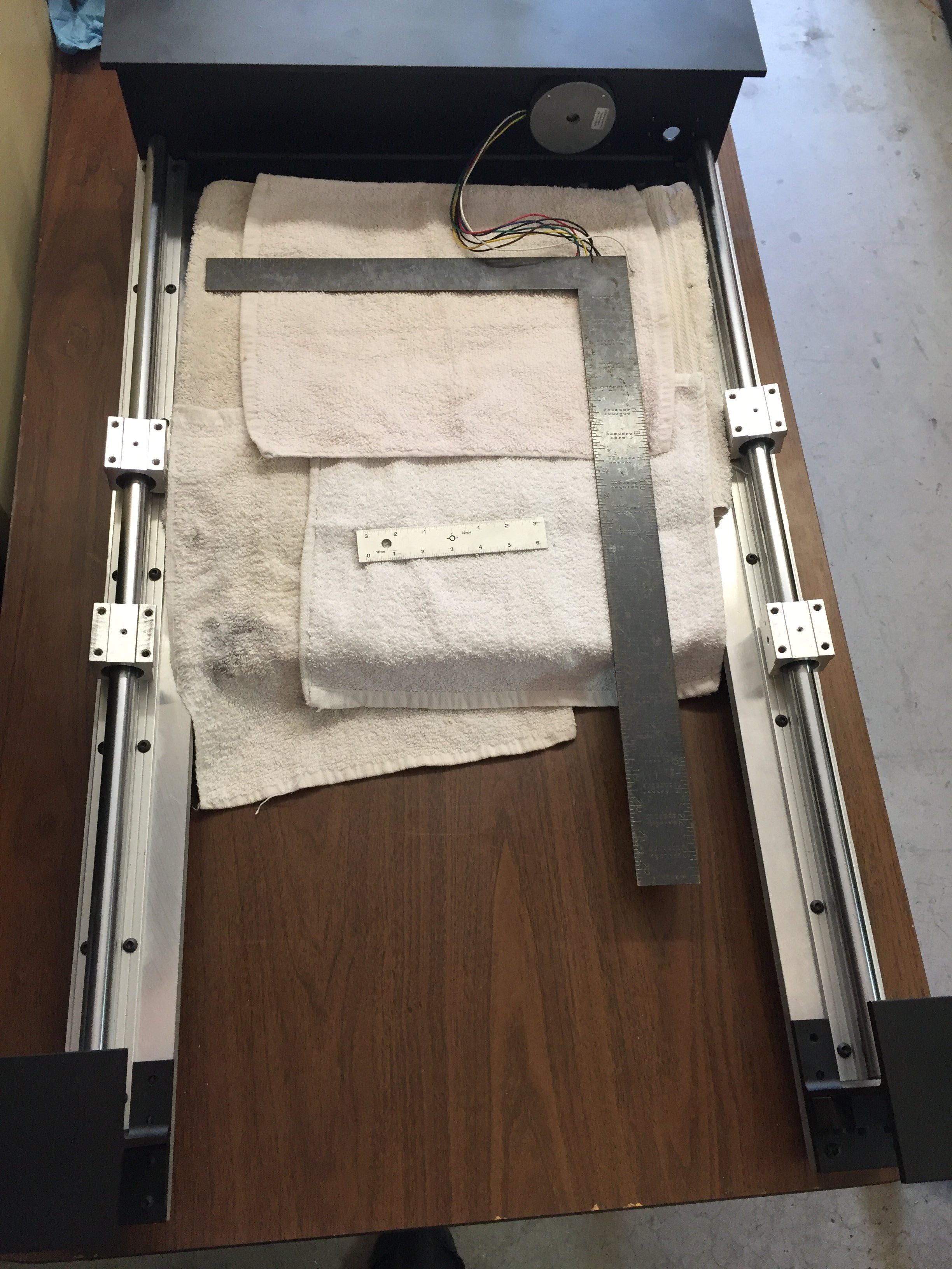
There is one problem with Powder Coating. Once you start, you want to powder coat everything! It's really important to keep towels over any flat surface. It would be unfortunate to have it marred by a careless twitch of a tool. The long bed is 1/2" MIC 6 aluminum plate and is very flat and smooth. The profile and the holes were all machined on a Flow Waterjet cutter. You can see the water jet in the background of my profile picture. Love that machine!!!
It really is astounding what less than $30 dollars will buy. In this case a very nice USB microscope.
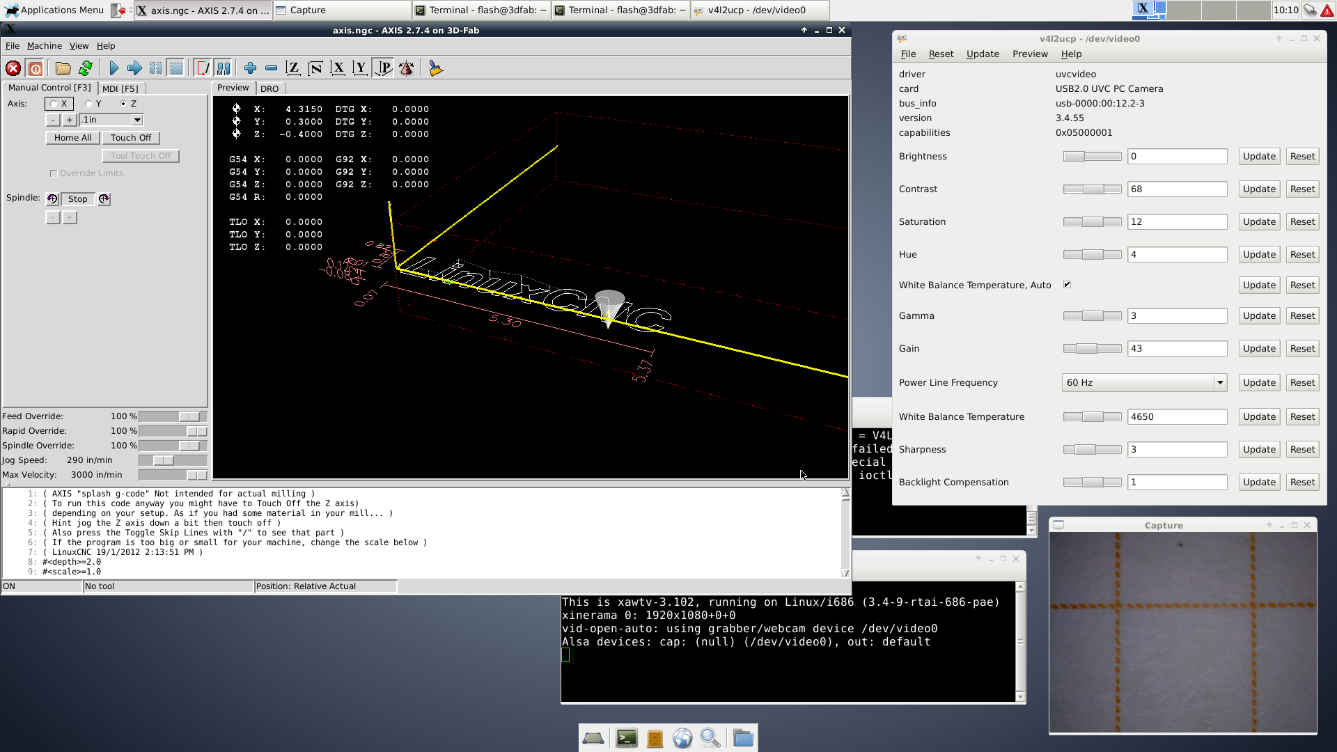
In the lower right corner is what the microscope sees. If it were moved closer and refocused, one (1) orange dash would fill the screen.
In the upper left corner is the linuxcnc user interface. Note the numerical readout indicating the tool head location. To align the system the camera is used to measure the distance between the spots produced by the laser and inkjet. This then provides an offset from the home positions of the tool head that may then be entered into the G-Code programs do the heavy lifting of actually cutting and printing of the LTCC ceramic tape.
Discussions
Become a Hackaday.io Member
Create an account to leave a comment. Already have an account? Log In.