 Andrew Starr
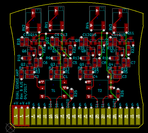
I wasn't able to find a ganged trimpot, unfortunately, so I'll need to adjust the positive- and negative-pulse amplifiers separately.
A project log for Ferrite Core Memory Module
A sub-project of the ED-64 Computer to document the development of a 64-byte ferrite core memory module
I wasn't able to find a ganged trimpot, unfortunately, so I'll need to adjust the positive- and negative-pulse amplifiers separately.
Discussions
Become a Hackaday.io Member
Create an account to leave a comment. Already have an account? Log In.
Thanks. Start with gains wound down to minimum, then with code on the arduino continually 'flipping' the cores on an address (doesn't matter which), go through each of the 8 bits, adjusting the relevant polarity up until the flip-flops 'SET' inputs are triggered. Then do the same with an adjacent address, adjusting the opposite polarities. Then run a complete memory test, adjust any bits that are still too low for memory locations that fail. Repeat until success :) I imagine it'll be a bit messier than this, but this is the basic jist of it.
Are you sure? yes | no
but I don't see a trimpot in your schematic at https://hackaday.io/project/11179/log/58252
Are you sure? yes | no
That screenshot is an LTSpice simulation schematic, not the kiCAD one
Are you sure? yes | no
yes, but i have no clue where the trimpot has been put on the schematic....
Are you sure? yes | no
'Gain is adjustable via R18/R9'
Are you sure? yes | no
This looks nice !
What's your procedure for the tuning ?
Are you sure? yes | no