 Trey German
Connectivity is a beautiful thing. It allows us to use our time more efficiently and interact with people on the other side of the planet. Without a doubt connectivity makes our world a better place, but more and more we are seeing examples of connectivity frustrating users instead of assisting them.
The most recent example of this was Revolv. This company developed a killer smart home hub and sold thousands of units to very excited customers only to have a questionable business decision brick the devices a few years later. Phillips almost made a similar mistake when they announced their Hue LED lightbulbs would only be allowed to interoperate with other Phillips products. Ultimately, until consumers are allowed to have full ownership of the firmware running on their devices, we will continue to see problems like this.
But it doesn't have to be this way. Polymorphic hardware is a concept for a solution to these problems we see from the IoT.
Polymorphism is traditionally a software concept that is used to describe code that can do different things depending on the objects and data passed to it. We can apply this to hardware by allowing end users to reprogram their device's firmware which will unlock a realm of new possibilities.
Let's look at one example:
Motion tracking wearables are all the rage these days. People love getting feedback from these devices and some folks even have multiple specialized devices for different movement applications. The funny thing is, most of these wearables share the same hardware solution: a microcontroller, Bluetooth, and a 9 axis sensor suite. If we apply the concept of polymorphism to these motion trackers, the user can now have a single device they could use to count steps, record and analyze a golf swing, and track a tennis match.
Because all polymorphic hardware will be reprogrammable by the end user these devices can never be bricked. If an app's cloud service ceases to exist, the user can simply reprogram the device and use it with another app which will prevent problems like those we've seen with Revolv and Phillips.
In the coming months, I will be developing hardware and software for this motion tracking example:
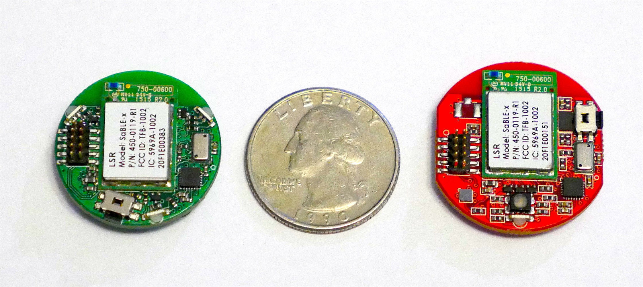
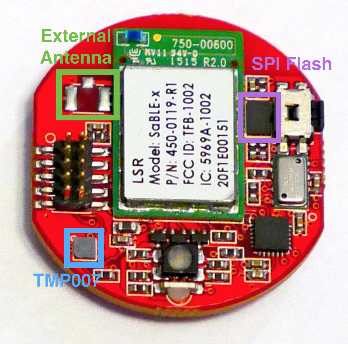
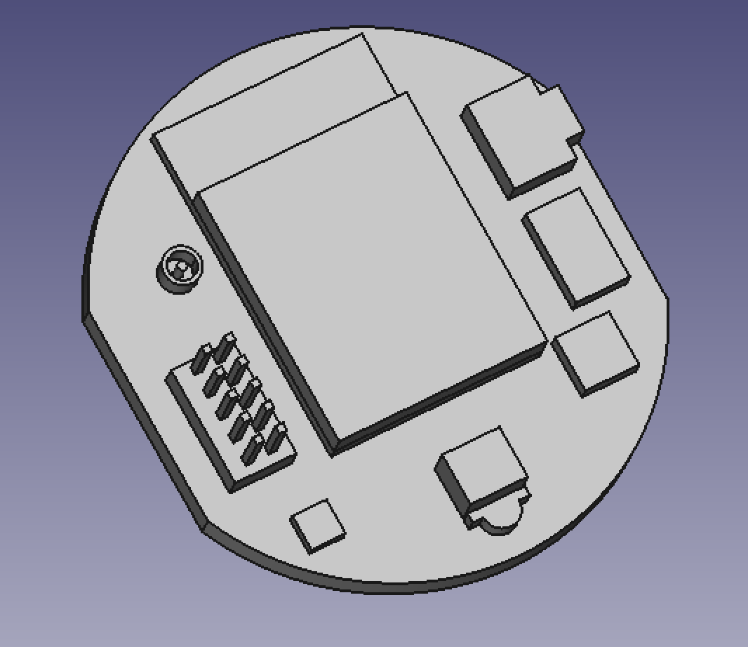
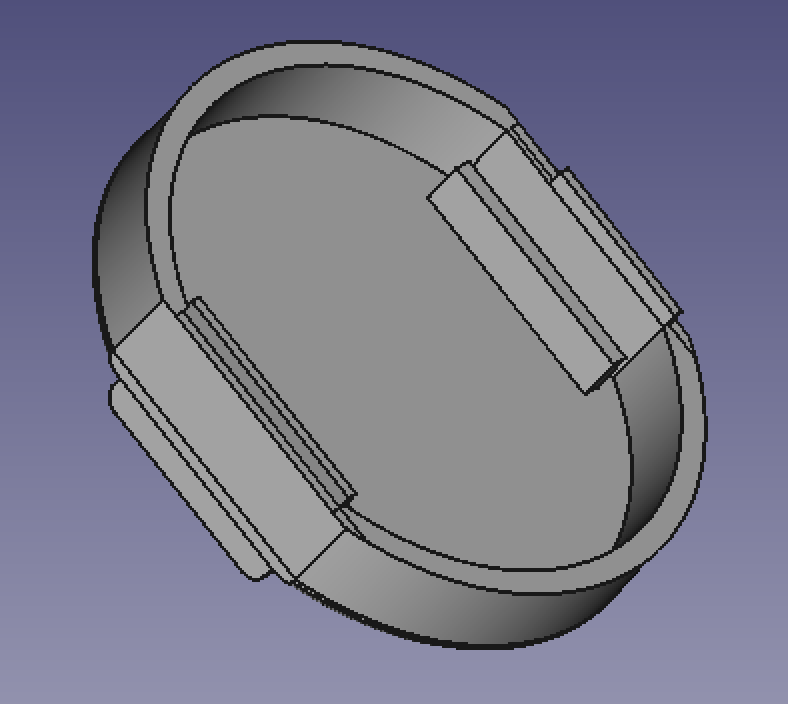
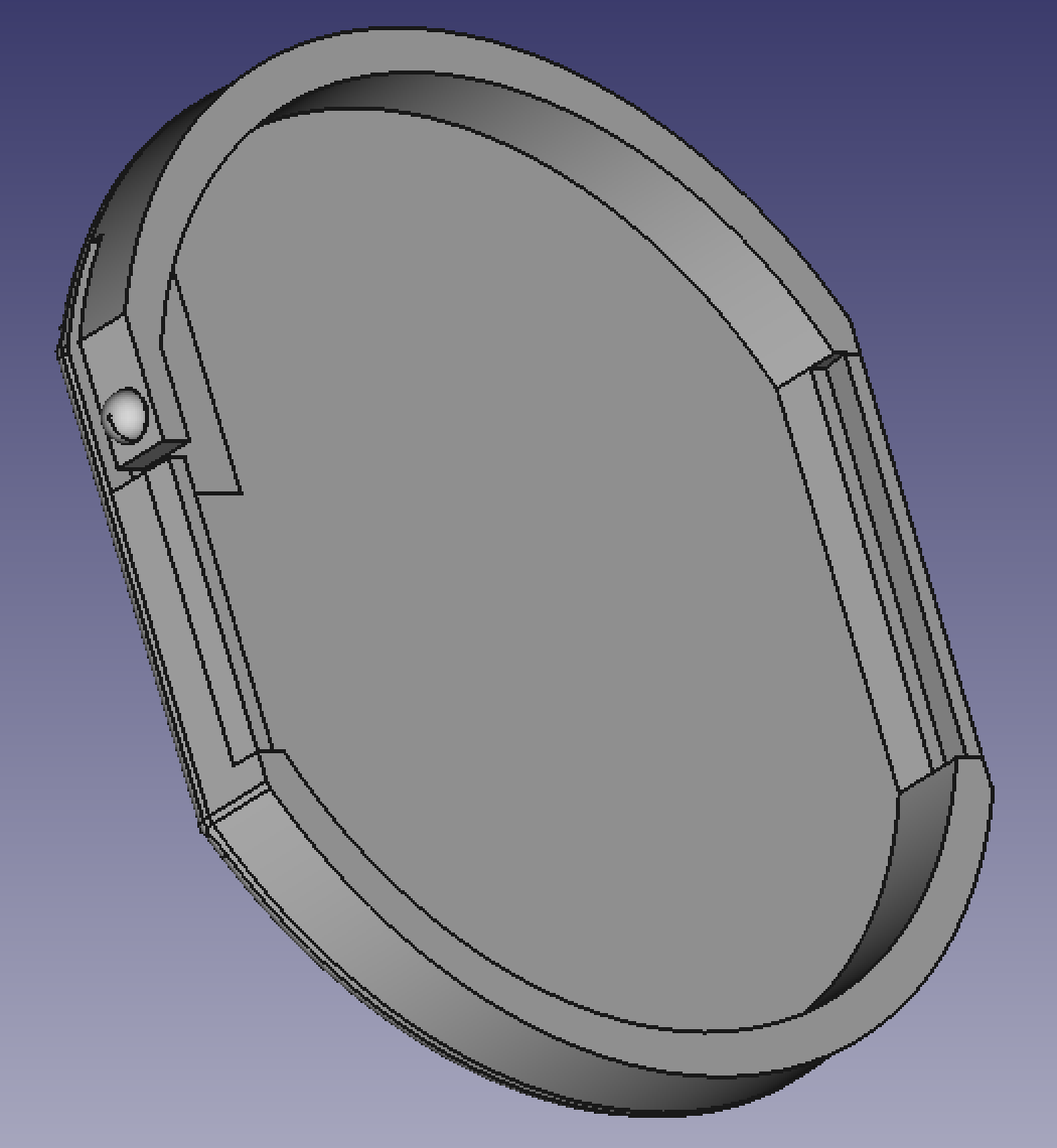
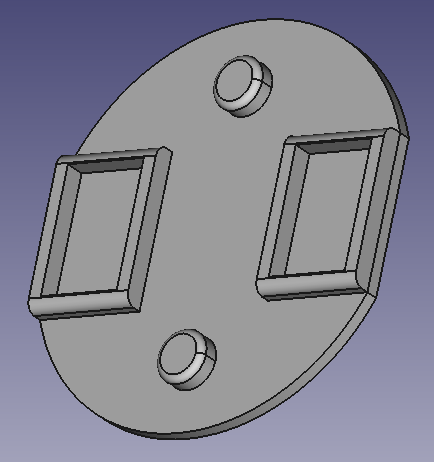
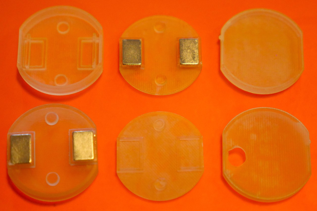
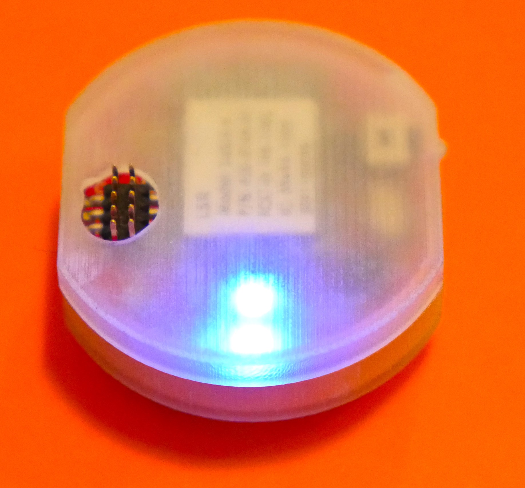
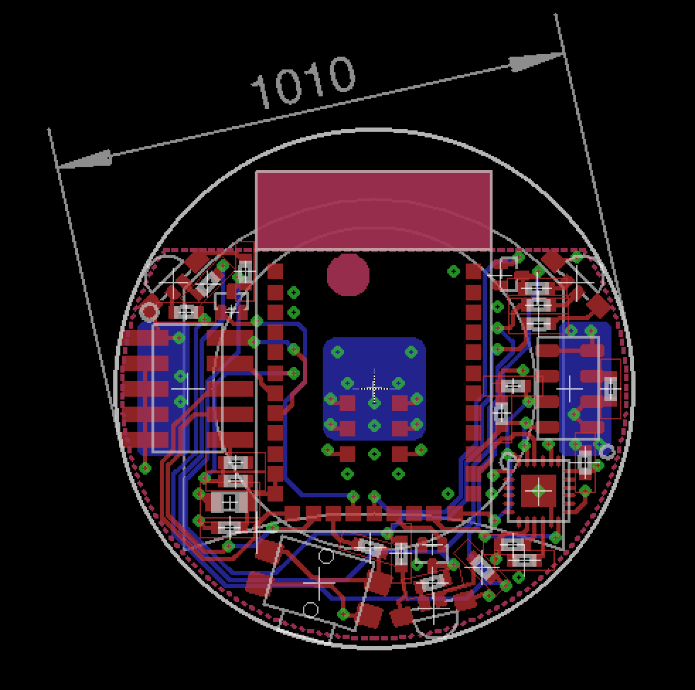
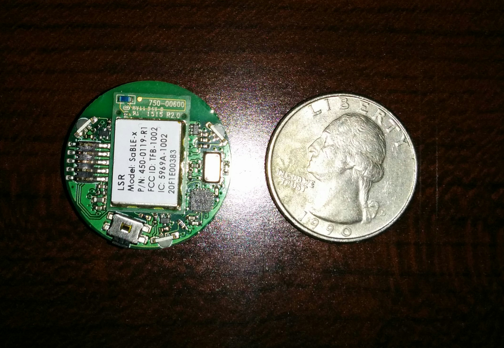
Hardware will be based on the TI CC2650 Bluetooth microcontroller. The board will be roughly the size of a quarter and will include a 9 axis + barometer sensor suite as well as a coin cell battery. Hardware will be licensed CC-BY-NC-SA.
Software for this project consists of two different pieces: embedded firmware and app SDK. The embedded firmware will be based off the TI SensorTag and will be modified to work with the custom hardware as well as add motion tracking features. The app SDK will use Apache Cordova to enable users to write apps with HTML5/JS. With the exception of the TI Bluetooth stack, all software will be licensed CC-BY.


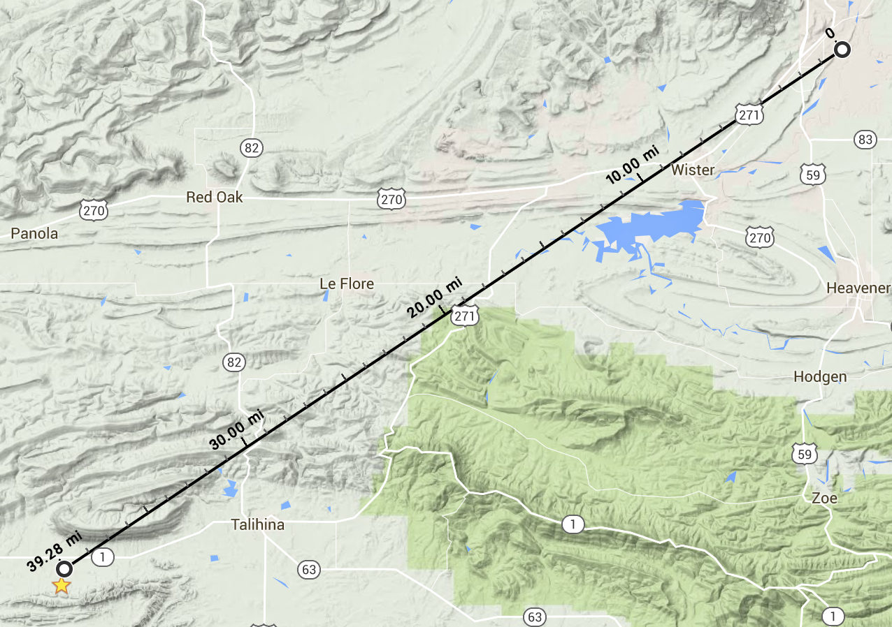


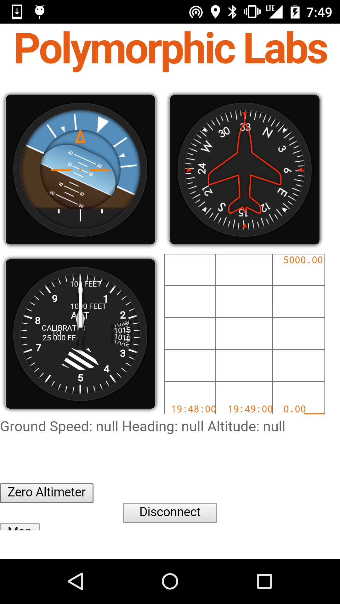 The final piece I wanted to add to the app was a map. This would prevent me from constantly having to switch between my paragliding app and Google Maps. While I could use the standard javascript Maps API, I found a better solution for Cordova apps:
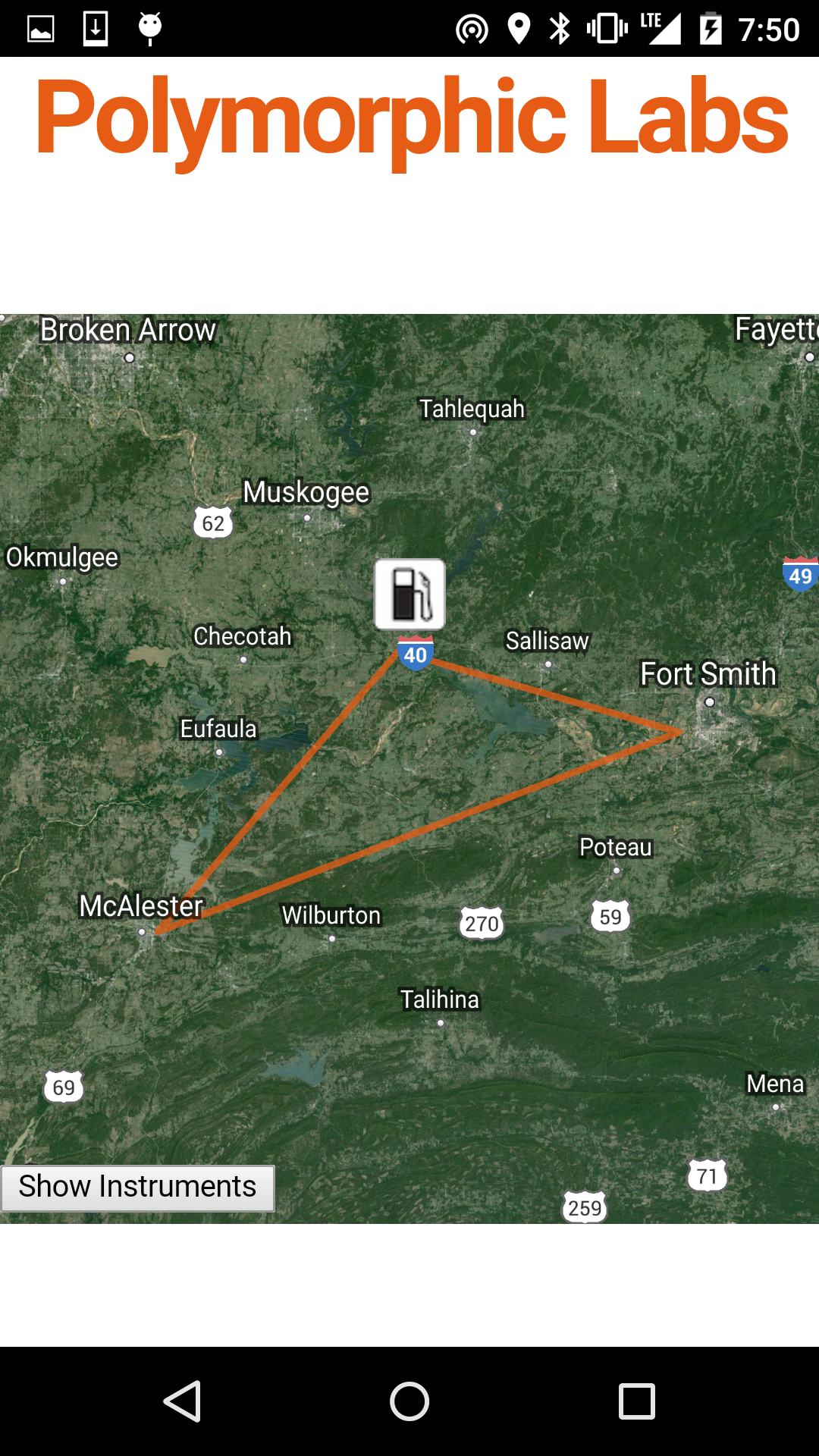
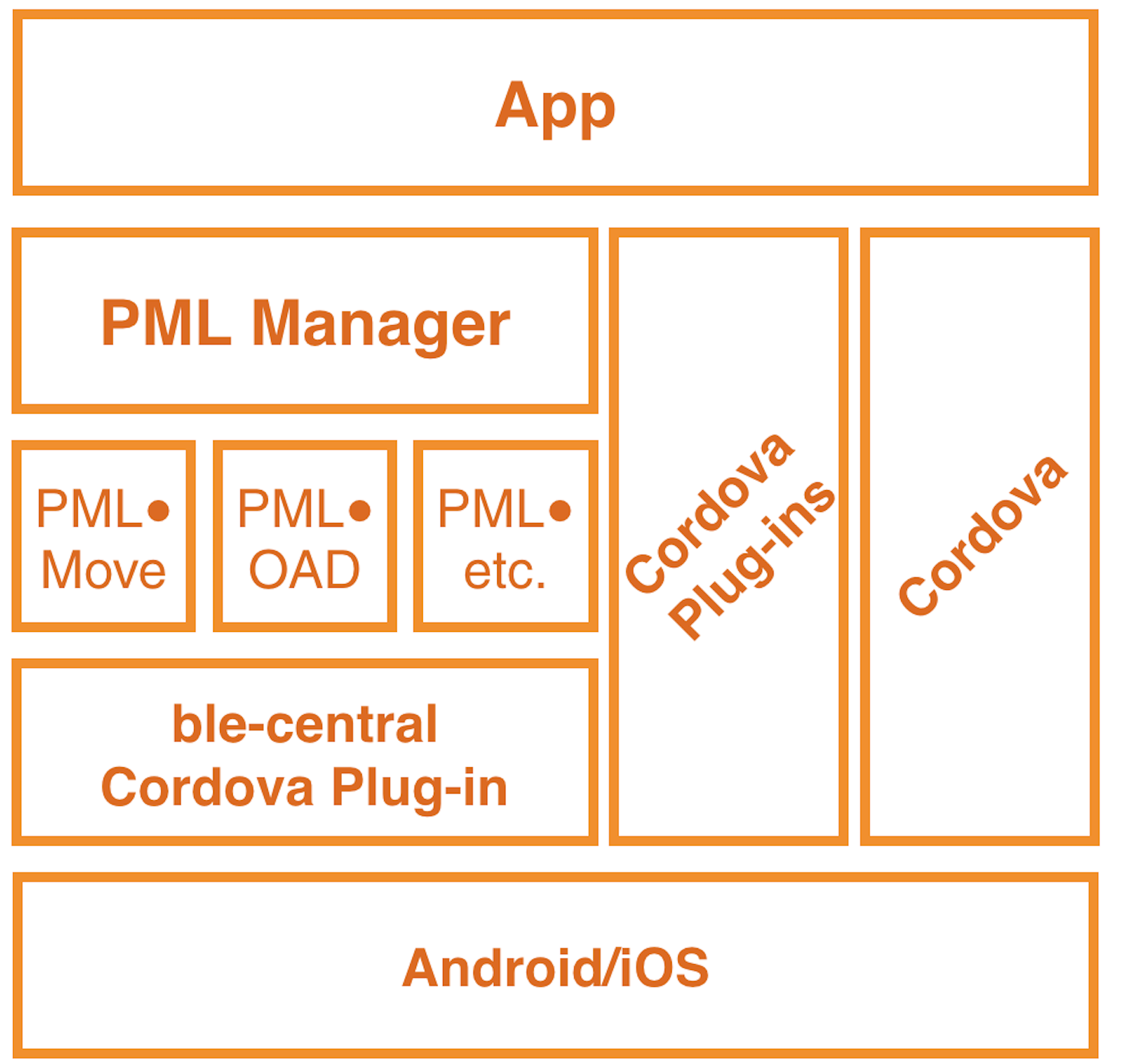 Just like any other piece of software, the SDK will be made up of a stack of other pieces of software:

 Pavel Zhovner
 Arya
Arya
 qquuiinn
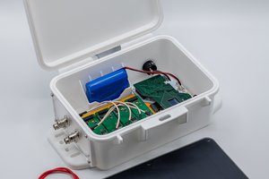
 Shah Selbe
Hi,
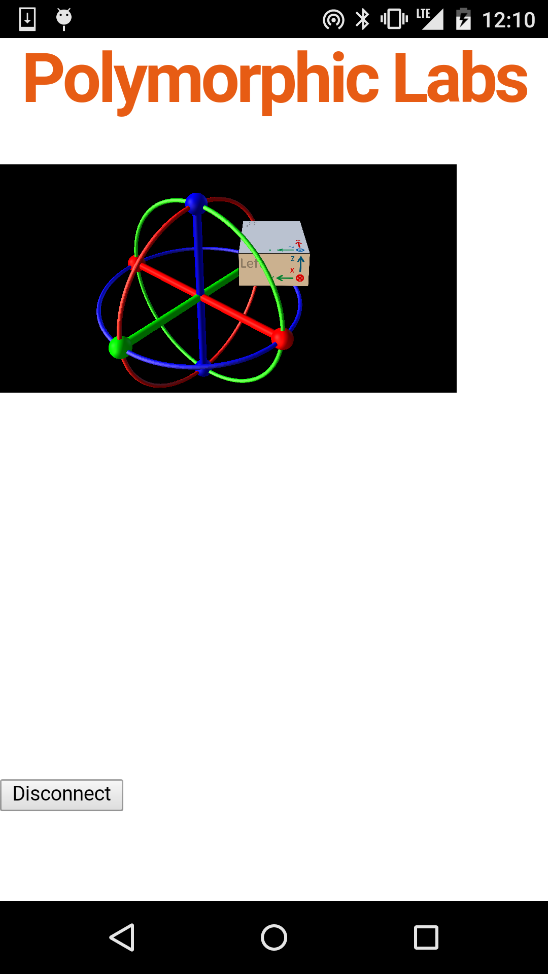
i am trying to implement my custom board, SABLE-X using MPU9250 TI Drivers and movement sensor services, with AHRS madgwick/mahony functions.
My sample frequency is 10Hz and deltat is 0.1.
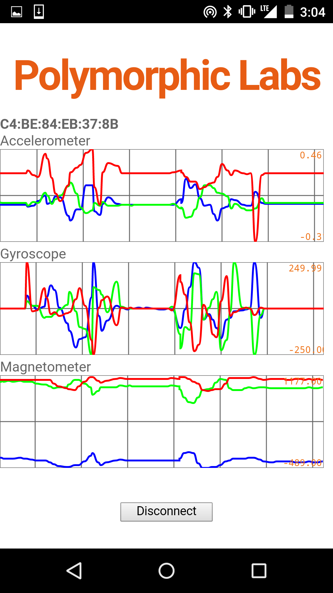
The yaw, roll and pitch are not looking good at the moment. I could not find on your github the received BLE values MAG/ACC/GYRO. I would like to check them against mine.
The sensortag app uses also the madgwick function and the sample rate is 10Hz there too.
So here is i build the 8 Bit values to 16 bit and send to madgwick function:
p, li { white-space: pre-wrap; }
int16_t value_save_msb = data[1];
int16_t value_save_lsb = data[0];
GyroX=((float)((int16_t)((value_save_lsb & 0xff) | (((int16_t)value_save_msb << 8) & 0xff00)))/ (float) 32768) * 250 * 1;
value_save_msb = data[3];
value_save_lsb = data[2];
GyroY=((float)((int16_t)((value_save_lsb & 0xff) | (((int16_t)value_save_msb << 8) & 0xff00)))/ (float) 32768) * 250 * 1;
value_save_msb = data[5];
value_save_lsb = data[4];
GyroZ=((float)((int16_t)((value_save_lsb & 0xff) | (((int16_t)value_save_msb << 8) & 0xff00)))/ (float) 32768) * 250 * 1;
value_save_msb = data[7];
value_save_lsb = data[6];
AccX=(((float)((int16_t)((value_save_lsb & 0xff) | (((int16_t)value_save_msb << 8) & 0xff00)))/ (float) 32768) * 2) * 1;
value_save_msb = data[9];
value_save_lsb = data[8];
AccY=(((float)((int16_t)((value_save_lsb & 0xff) | (((int16_t)value_save_msb << 8) & 0xff00)))/ (float) 32768) * 2) * 1;
value_save_msb = data[11];
value_save_lsb = data[10];
AccZ=(((float)((int16_t)((value_save_lsb & 0xff) | (((int16_t)value_save_msb << 8) & 0xff00)))/ (float) 32768) * 2) * 1;
value_save_msb = data[13];
value_save_lsb = data[12];
MagX=(((float)((int16_t)((value_save_lsb & 0xff) | (((int16_t)value_save_msb << 8) & 0xff00))) *(float)(49120/32768)));
value_save_msb = data[15];
value_save_lsb = data[14];
MagY=(((float)((int16_t)((value_save_lsb & 0xff) | (((int16_t)value_save_msb << 8) & 0xff00))) *(float)(49120/32768)));
value_save_msb = data[17];
value_save_lsb = data[16];
MagZ=(((float)((int16_t)((value_save_lsb & 0xff) | (((int16_t)value_save_msb << 8) & 0xff00))) *(float)(49120/32768)));
MadgwickAHRSupdate(GyroX*M_PI/180, GyroY*M_PI/180, GyroZ*M_PI/180, AccX, AccY, AccZ, MagX, MagY, MagZ);
double R11 = 2.*q0*q0 -1 +2.*q1*q1;
double R21 = 2.*(q1*q2 - q0*q3);
double R31 = 2.*(q1*q3 + q0*q2);
double R32 = 2.*(q2*q3 - q0*q1);
double R33 = 2.*q0*q0 -1 +2.*q3*q3;
double phi = qAtan2(R32, R33 );
double theta = -qAtan(R31 / sqrt(1-R31*R31) );
double psi = qAtan2(R21, R11);
yaw = phi;
pitch = theta;
roll = psi;