Close
0%
0%

RRB - The Radio Rewind Button

Radio killed the Video-recorder Star

Similar projects worth following
The Radio Rewind Button (RRB) is a FM radio with a rewind function to catch up with the last few minutes of the show. Streaming audio services form your internet radio stations also don't have a rewind option, so I might need a line input as well.
This idea started with my wife wishing to catch a piece of talk in the radio where we missed the beginning of the story or one of her favourite songs playing that she would like to hear from the beginning right now. Putting 1+1 (idea + implementation) together, this is the perfect entry for this year's HaD price. Makes her happy and gives me an exciting and challenging project.
Things are coming together: base platform and daughter card are in the house. Vivado SW is installed. Now everything needs to be wired up and then the adventures in Ones-and-Zeros land is going to start.
The KiCad Design for the 'Shield' and an initial Blinky project can be found in the Github repository for this project. See links section.

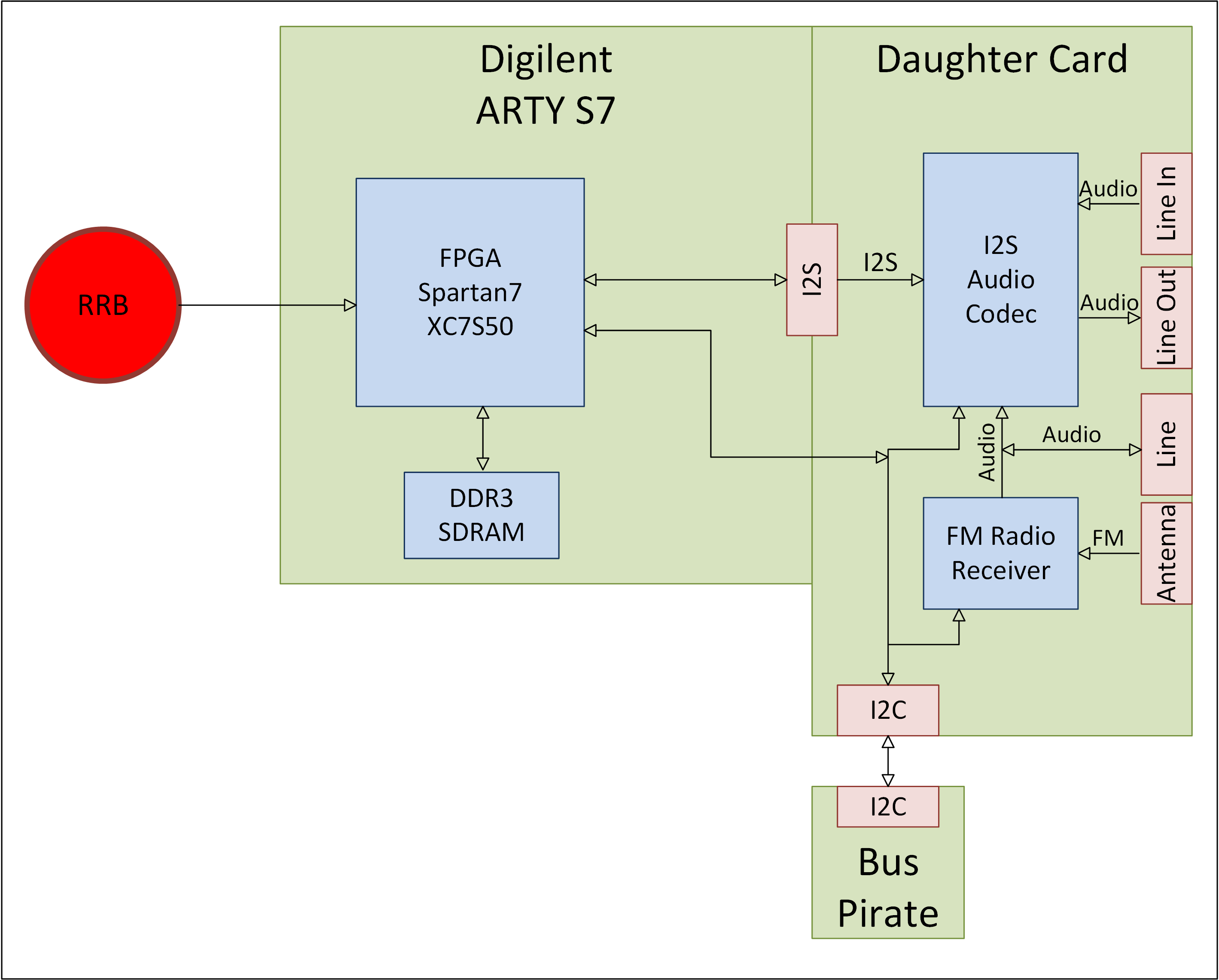
The idea is to have a FM receiver chip with I2S interface to get the audio data into the digital domain as quickly as possible. The FPGA implements a ring buffer inside the SDRAM memory with an I2S to line out back end. A small controller, probably Arduino is going to to control the radio station and a small display with a all necessary information as FM frequency, rewind metric and memory telemetry. Finally the main controller, a BIG red button to rewind your radio and give superior listen experience.

The concept changed somewhat, I decided to run the analog audio rom the FM reciever chip to the audio processor and use its I2S interface as the only digital link. Makes for a much cleaner data flow. 

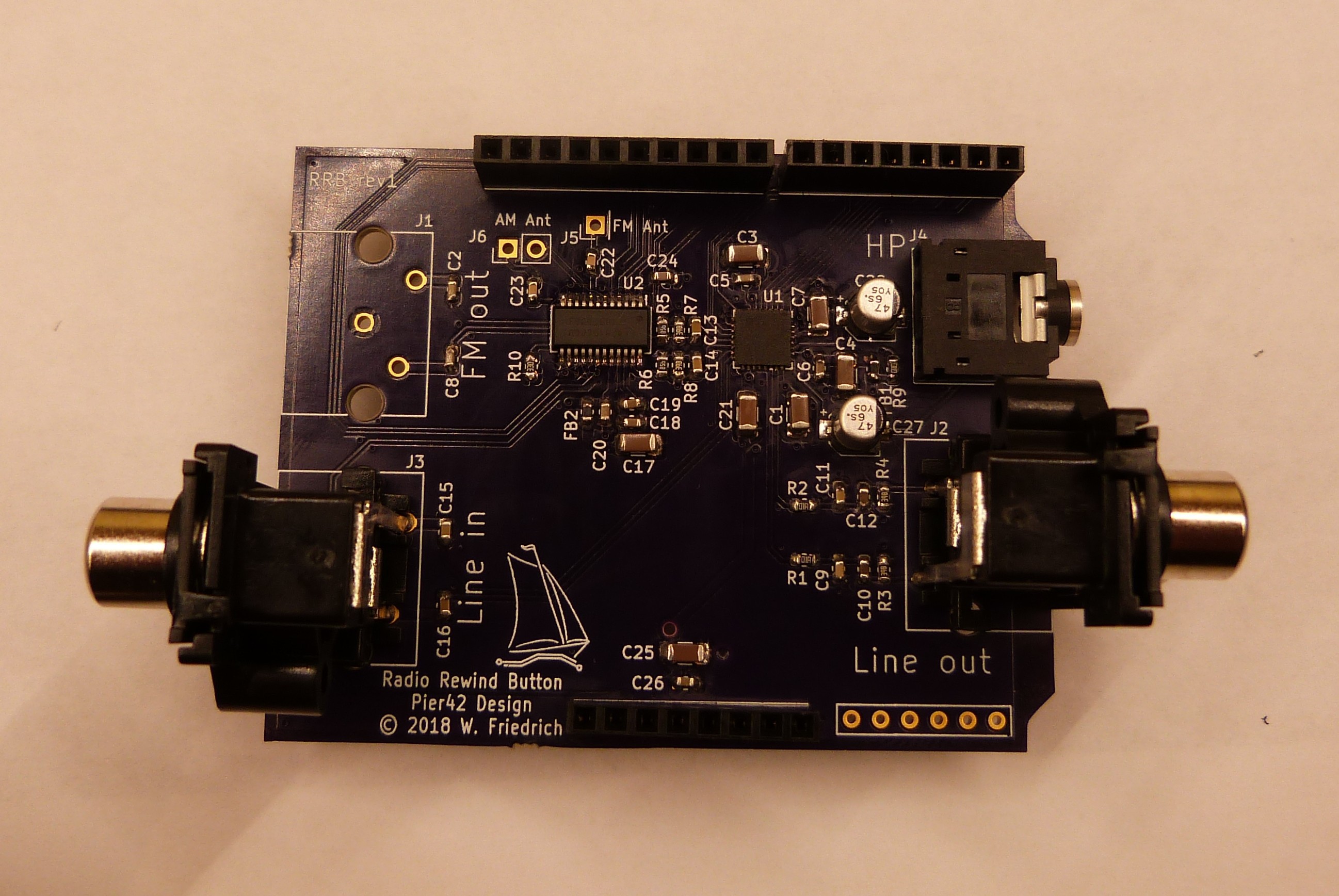
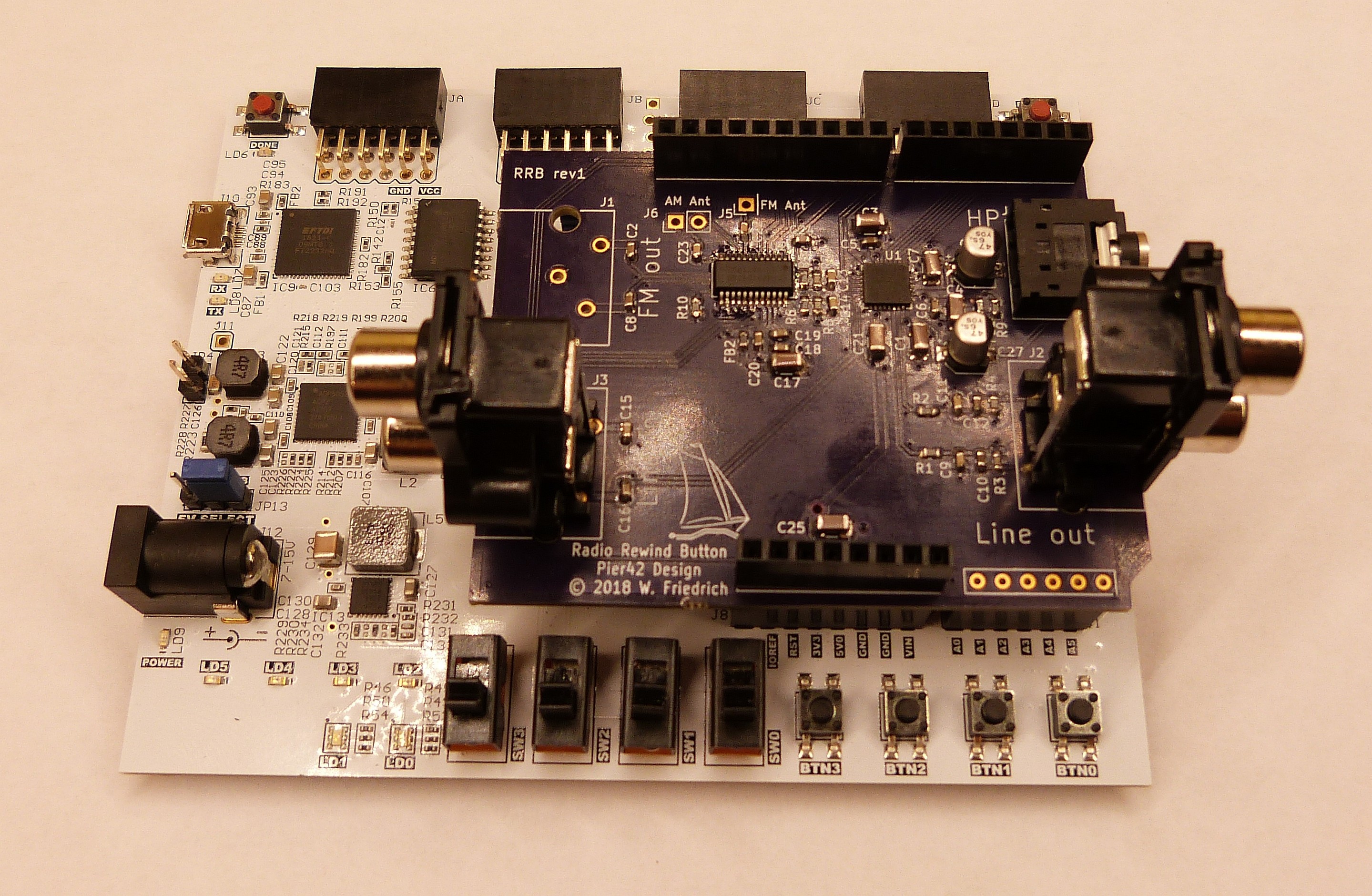
The base platform is going to be a Digilent ARTY S7 board which provides 256MB of SDRAM already, so I don't have to do the risky SDRAM over PMOD interface. The daughter card with all audio circuit will be in a Arduino Shield formfactor for potentially later re-use. 

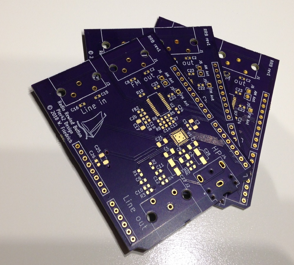
The design and layout is finished, schematic (with fixes) and assembly drawing are in the files section.

And to fill in some gaps: With 256 MB of memory all used in one big ring buffer and assuming 44.1 kSamples/sec, my math adds up to just under 25 minutes of rewind time, which should be plenty.

AD_P42-RRB_rev1.pdf

Assembly drawing Rev1

Adobe Portable Document Format - 44.90 kB - 08/20/2018 at 00:35

Preview
Download

P42-RRB_rev1 w fixes.pdf

Schematic Rev1 with fixes.

Adobe Portable Document Format - 1.07 MB - 08/20/2018 at 00:19

Preview
Download

  • 1 × BIG red button Yes
  • 1 × Digilent ARTY S7 Spartan7 FPGA + SDRAM dev board
  • 1 × Silicon Labs Si4730 BROADCAST AM/FM RADIO RECEIVER with I2S OUTPUT
  • 1 × TI PCM3070 Find a different Stereo Audio Codec
  • 1 × CUI Inc. RCJ-2223 Dual RCA connector red/white stacked

View all 6 components

  • It seems to be audio

    MagicWolfi09/26/2018 at 01:46 0 comments

    Configuration of the FM receiver was very straight forward. Here is the script in Teraterm language, my preferred choice of terminal software.

    ; power up the FM receiver: CTS and GPO2 enabled, external RCLK, analog output
    sendln '[0x22 0x01 0xc0 0x05]'#13
    pause 1
    ; Get version information
    sendln '[0x22 0x10][0x23 r:8]'#13
    pause 1
    ;set FM tune frequency to 8990 = 0x231E
    sendln '[0x22 0x20 0x00 0x23 0x1E]'#13
    pause 1
    ;Use GET_INT_STATUS (command 0x14) or hardware interrupts Until STC bit is set
    sendln '[0x22 0x14][0x23 r:2]'#13
    pause 1
    ;Call FM_TUNE_STATUS With INTACK bit set (command 0x22)
    sendln '[0x22 0x22 0x01]'#13
    pause 1
    

    To be added: scope plot of the line out signal and description of listening to it.

  • PCB ver 1.1

    MagicWolfi09/01/2018 at 03:35 1 comment

    2 little issues are on the board.

    1. The GPO1 signal on the Si4731 FM chip connected to the ARTY board is held low during RESET. To enable I2C configuration for the chip, it needs to be pulled high by the internal pull-up resistor (weak). A quick cut of the trace fixed this.
    2. The PCM3070 datasheet has unclear information about the REF signal. A schematic has it connected to 3.3V, the pin description states on a capacitor connected for noise suppression. Of course I picked the wrong one and connected it to 3.3V. This fix was a little bit tricky because it was connected to 3.3V between the pin and the cap by a via to a bottom layer trace. But drilling out the via barrel and leaving the track around it intact fixed this as well.

    The uploaded schematic shows the 2 fixes already.

    Happy configuring.

  • Configuration through I2C

    MagicWolfi08/20/2018 at 01:16 0 comments

    For ease of configuration I am hooking up a Bus Pirate (or as I prefer to call him Bus Privateer, because they are the good pirates) to the I2C interface and run scripts with all config commands through my terminal program of choice (Teraterm).

    Example (might be good to put this into the instructions section):

    Initial commands:

    Bus Pirate configuration and run macro (1) to scan all device:

    HiZ>m
    1. HiZ
    2. 1-WIRE
    3. UART
    4. I2C
    5. SPI
    6. 2WIRE
    7. 3WIRE
    8. LCD
    9. DIO
    x. exit(without change)
    
    (1)>4
    Set speed:
     1. ~5KHz
     2. ~50KHz
     3. ~100KHz
     4. ~400KHz
    
    (1)>4
    Ready
    I2C>(1)
    Searching I2C address space. Found devices at:
    0x22(0x11 W) 0x23(0x11 R) 0x30(0x18 W) 0x31(0x18 R)
    

     7bit address 0x11 is the Si4731 FM receiver, 0x18 is the audio processor TI PCM3070. Nice.

    Si 4731: Power up and request revision information:

    I2C>[0x22 1 0xc0 5]
    I2C START BIT
    WRITE: 0x22 ACK
    WRITE: 0x01 ACK
    WRITE: 0xC0 ACK
    WRITE: 0x05 ACK
    I2C STOP BIT
    I2C>[0x23 r]
    I2C START BIT
    WRITE: 0x23 ACK
    READ: 0x80
    NACK
    I2C STOP BIT
    I2C>[0x22 0x10][0x23 r:8]
    I2C START BIT
    WRITE: 0x22 ACK
    WRITE: 0x10 ACK
    I2C STOP BIT
    I2C START BIT
    WRITE: 0x23 ACK
    READ: 0x80  ACK 0x1F  ACK 0x36  ACK 0x30  ACK 0x00  ACK 0x00  ACK 0x37  ACK 0x30
    NACK
    I2C STOP BIT

    PCM3070: Write 0x42 into the page select register and read back for testing as this one does not have an ID or revision register

    I2C>[0x30 0x00 0x42]
    I2C START BIT
    WRITE: 0x30 ACK
    WRITE: 0x00 ACK
    WRITE: 0x42 ACK
    I2C STOP BIT
    I2C>[0x30 0x00][0x31 r]
    I2C START BIT
    WRITE: 0x30 ACK
    WRITE: 0x00 ACK
    I2C STOP BIT
    I2C START BIT
    WRITE: 0x31 ACK
    READ: 0x42
    NACK
    I2C STOP BIT

    That was easy. Now I have to read all the programming and configuration guide.

  • PCB something PCB

    MagicWolfi08/10/2018 at 11:56 0 comments

    PCBs are ordered, so are the parts. Boards will be purple and this log will be the collector for assembly and bringing up the hardware. Looking forward soldering the QFN32 0.5mm pitch IC.

    Update 13. Aug: Parts are here from Digikey. Boards are in manufacturing.

    Update 14. Aug: PCBs are shipped from OSH Park. This is getting exciting (happens every time when FR4 is on the way). 

    Update 17. Aug: PCBs came in yesterday, beautiful as always. Thanks @oshpark .

    Now the fun part starts with hand soldering QFN32 0.5mm pitch. :))

    This was a piece of cake and this is how it looks like:


    And plugged into the ARTY-S7 board.


    Also, I have established I2C communication to the PCM3070 audio processor and the Si4731 FM receiver through the trusted bus pirate.

    Next log: bug fix report.

  • New base platform

    MagicWolfi07/23/2018 at 00:30 0 comments

    I just scored a DIGILENT ARTY S7 FPGA board, which is the perfect platform for the RRB project. It has a Spartan7 XC7S50 FPGA and best of all, 256MB DDR3 SDRAM on board already. So I don't have to run a SDRAM interface over PMOD connectors, which was risky from the beginning. And it has Arduino compatible (3.3V) headers. Now I can design a shield with all my crazy audio hardware. All block diagrams will be updated in the near future. Good times.

    This is the new system concept.

  • More components

    MagicWolfi04/20/2018 at 13:28 0 comments

    Just found out that the NXP UDA1380 is end of life:-(. Looks like I am back to component hunting again. Looking for a Audio line in to I2S and I2S to line out codec.

    As a replacement, the TI PCM3002 looks very promising. Simple IO but good audio characteristics. I will do some more datasheet reading, but so far it does everything I need. Analog in and out and a digital audio interface, everything controlled through a weird 3-wire interface.PCM3002 Block DiagramAnother option would be the TI PCM3070 audio codec chip, which has 3 audio input pairs. This would change the architecture quite a bit, running the FM radio audio stream analog into the PCM3070 and only have a single I2S interface for all digital audio data. Also the control interface is I2C which would help in my quest to save signal pins between the ElbertV2 and my RRB daughter card.
    PCM3070 Block DiagramDecisions, decisions.

  • Memory size and let's do the time warp again...

    MagicWolfi04/17/2018 at 01:26 0 comments

    Assuming CD quality, I have 44100 samples/sec in 16 bit. For stereo this is 176400 Bytes/sec or 10584000 Bytes/minute. The smallest SDRAM with availability and second source is 64Mbit x 8 = 67108864 Bytes. So I will have about 6 Minutes and 20 seconds (in NA units this is 6 1/3 minutes ;-) time warp rewind time. This should be more than enough to listen to the missed news and not many songs are longer than 6 minutes, unless your really like November Rain or Pink Floyd and have a radio station that plays the songs to the very end and not only half </rant>.

  • Components

    MagicWolfi04/06/2018 at 00:53 0 comments

    Heart of the prototype will be a Numato Elbert V2 FPGA board. It has a Xilinx Spartan3 XC3S50A FPGA, which is somewhat unfortunate for me as a lifelong Altera guy but they all speak VHDL.


    It should be large enough to handle a SDRAM core and 3 I2S interfaces. The board has 39 dedicated IOs and I am sure the 6 LEDs and 8 DIP switches can be re-purposed if necessary. The buttons might come in handy for a user interface, except the big red button of course, which will be there no matter what.  32 IOs are located on 4 PMOD connectors. the daughter card will connect through them and will mainly hold the SDRAM interface (~30GPIOs for a 64M x 8bit device). 64Mx8 is the smallest I could find with an 8bit data bus to save pins and available quantities. Also on the daughter card will be the FM radio and the line in and out interfaces. Separate control interfaces will go to an Arduino controller, could be as simple as an I2C interface. The prototype might connect to a PC for user IO, but the end goal is a small display showing the radio station and other useful data. The big red button was part of a Sparkfun dumpster dive shipment, waiting patiently for its opportunity to shine.

View all 8 project logs

Enjoy this project?

Share

Discussions

krisedwards wrote 08/09/2018 at 11:22 point

You could also use RDS to implement commercial skipping.

  Are you sure? yes | no

MagicWolfi wrote 08/09/2018 at 14:00 point

Interesting idea, I hate commercials. I wasn't aware that RDS has a commercials code ID. And regular radio would need to play a little slower to build up a buffer for the skipping. Yay, feature creep.

  Are you sure? yes | no

krisedwards wrote 08/10/2018 at 12:23 point

It doesn't have commercial codes, but you could watch for specific names if your doing talk radio. Just delete audio that doesn't  match the host's name.  If you're doing music radio, you could check titles against a song title db and reject anything that wasn't there..or, since most stations just run generic rds tags during commercial breaks you could reject anything when the rds hasn't changed in 5 min.  Anyway, thanks for the project

  Are you sure? yes | no

Saabman wrote 08/08/2018 at 20:32 point

everyday I get in my car to drive to work I think I want a TiVo for my radio. Watching with great interest. 

  Are you sure? yes | no

MagicWolfi wrote 08/09/2018 at 13:57 point

Thanks. That make 2 potential buyers. There might be a mass market ;)

  Are you sure? yes | no

jeffw wrote 08/20/2018 at 19:05 point

Everyday I get in my car, I use the rewind function built into the car's  (Toyota Highlander) audio system. Nice project,, but not a new invention

  Are you sure? yes | no

talfordjunk wrote 05/20/2020 at 01:10 point

Same here.  Seems it would be so simple for an automotive OEM or an aftermarket manufacturer like Sony or JVC to implement. All I want is the ability to skip back 10 seconds for every press of the rewind button so I can catch that bit of news I missed or that phone number/website they rattled off too quickly.

  Are you sure? yes | no

[deleted]

[this comment has been deleted]

MagicWolfi wrote 04/21/2018 at 01:56 point

Nice, sounds like a useful implementation. I hope you had a backup of the scripts. I am a hardware guy, so I try to do as much as possible with as little as possible programming.

  Are you sure? yes | no

Mike Szczys wrote 04/03/2018 at 15:07 point

I love this idea! It would be very neat to have the playback after rewind be 5-10% too fast so that over time you catch up again.

  Are you sure? yes | no

MagicWolfi wrote 04/04/2018 at 00:45 point

Thanks Mike. The faster playback makes absolute sense. Best implementation might be to speed it up dynamically to hide the fact that it is faster than normal. Would spoil the favourite song if it is noticeable. Speech might be more forgiving. 

  Are you sure? yes | no

Similar Projects

Does this project spark your interest?

Become a member to follow this project and never miss any updates