 Aron Molnar
2016 Hackaday Prize entry video:
There are two functioning models right now:
- The linear sensor (hereinafter referred to as Linear FCDT) that has the proper geometry (Length/Radius) ratio can measure tilt in a 40 degrees interval and has a relatively good resolution.
- The circle-like sensor (hereinafter to as Toroid FCDT) that has the proper geometry can measure tilt in a 360 degrees interval.
There is a little demonstration video of the circle-like sensor in working:
(In this video, the sensors' signal conditioners' (Analog Devices AD598) output is measured with a multimeter, and the measured values are sent to a laptop via RS-232 serial port. Then a LabVIEW program calculates the tilt based on the sensors' characteristic, and indicates it.)
The idea
First, let's imagine three coils placed next to each other. The middle coil is called the primary coil, and the two on the sides are called the secondary coils. Let's place an iron core into the coils' air gap, and excite the primary coil with an AC signal (normally with a sine wave). Now, what will happen? Well, it's basically functioning like a transformer, so depending on the iron cores' position different voltages are being induced in the secondary coils. Then, if I move the iron core, the induced voltages in the secondary coils are changing. With the proper signal conditioning circuit, I made a linear displacement sensor! (By the way, these machines are called LVDTs - Linear Variable Differential Transformers, and are widely used in industry.) There's an awesome website where there is a more awesome simulation about the working of an LVDT: http://www.rdpe.com/ex/hiw-lvdt.htm
Cool. Now, you'd probably heard about what ferrofluid is (if don't: https://www.youtube.com/watch?v=5APHa7vscoI). Ferrofluid is a ferromagnetic fluid which contains nanoparticles of metal, that's why it's being attracted by magnets, and basically functioning like "liquid metal".
The basic idea is that what would happen if you'd remove the LVDT's iron core and replace it with a ferrofluid filled glass tube. Somehow like this:
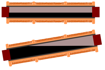
Well, the ferrofluid would act like the replaced iron core, and as you tilt the sensor, the induced voltages in the secondary coils would change depending on the tilt, so you'd make a tilt sensor!
Linear FCDT
And that's it. That's the basic concept behind the sensor. I call this arrangement the Linear FCDT(Linear - the coils placed "linearly next to each other; FCDT - Ferrofluid Core Differential Transformer)
Our next task is to make experiments with it. First, we'd like to know what is the maximum value of tilt it can measure. Based on experiments I made - as I mentioned earlier - it's a +/- 20 degrees interval. Why? Well, if you reach a specific state of tilt, the ferrofluid runs out from the air gap of one of the secondary coils, like this:
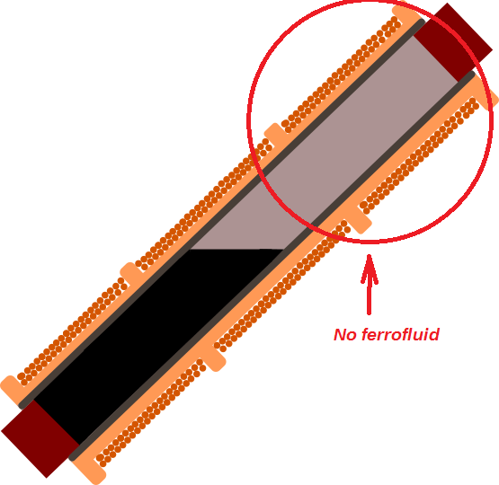
Thus, there won't be generated any voltage in that secondary coil (or the generated voltage would be insignificant), so the sensor's output voltage will deteriorate.
Our next thing to do is to make a sensor which can measure in a larger range, but first, let's measure the accuracy of this arrangement! After hours and hours of making an extremely precise measurement, I came up with this diagram:
(How the precise resolution measurements were made: https://hackaday.io/project/11225-a-new-high-accuracy-tilt-sensor/log/46066-how-the-precise-resolution-measurements-were-made) 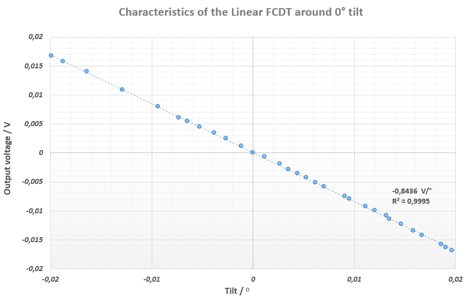
Theoretical background of the Linear FCDT: https://hackaday.io/project/11225-a-new-high-accuracy-tilt-sensor/log/46957-theoretical-background-of-the-linear-fcdt
Toroid FCDT
So, if we would like to have a greater measuring range than 40 degrees, we'd have to redesign the whole sensor. The problem with the Linear FCDT was that the ferrofluid ran out from one of it's secondary coils after reaching + or - 20 degrees of tilt. What if we bend a glass tube like a circle, fill it half with ferrofluid, and turn the coils around it toroid-like (hence Toroid FCDT) with the secondaries covering the half-half of the glass tube's surface and the primary coil covering the whole surface? It'd look something like this:
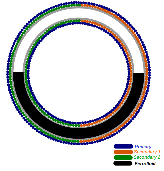
Now, with this arrangement, there's always some ferrofluid in both of the secondaries, so there's always some voltage generating in them, thus it's output will be fully linear in 360 degrees. Let's measure if it's true:
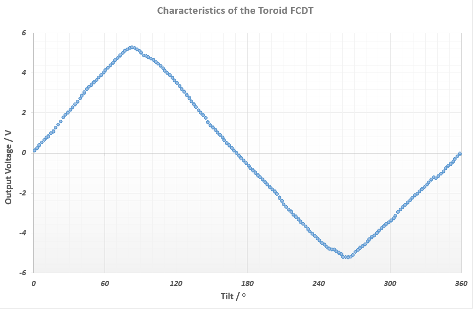
On the X-axis you can see that the tilt stretches to 360 degrees, and that the sensor's output voltage is always changing. (And there is one thing that can cause problem: if observe the diagram carefully, you can see that there are output voltages that can mean different tilt values at a time - you can't really know what tilt value belongs to an output voltage. Happily, there is a really simple solution: we should add two more coils facing with each other, and when the ferrofluid is inside one of the plus coils' air gap, there's voltage generated in the coil, and we know exactly where we are. Simple and elegant.)
And there is the theoretical background of this arrangement: https://hackaday.io/project/11225-a-new-high-accuracy-tilt-sensor/log/46947-theoretical-background-of-the-toroid-fcdt
Signal Conditioning
When I first built the sensor, I faced with the problem of signal conditioning. The problem is that when you excite the primary coil with a sine wave, the induced voltages in the secondaries will also be sine waves. The induced voltages' amplitude will depend on the tilt, of course, but how can I know exactly how is it changing? Should I connect the secondary coils to an oscilloscope and manually read the amplitude change of their signals? Nope, that would be painful, almost impossible, and very expensive.
We'd need a DC output, which would depend on the tilt. To get a DC signal, we should add (or subtract - it depends on the signal conditioning method) the absolute value of each sine wave to each other, and pass it through a low-pass filter. There is a very good article about this: http://www.mikesflightdeck.com/lvdts/lvdts.html
My first attempt was to use this signal conditioning schematic which I found on Mike's Flight Deck website (see the link above):
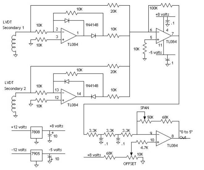 I designed the board to it in Eagle, made the PCB, soldered the parts, and the first signal conditioning circuit was ready to go:
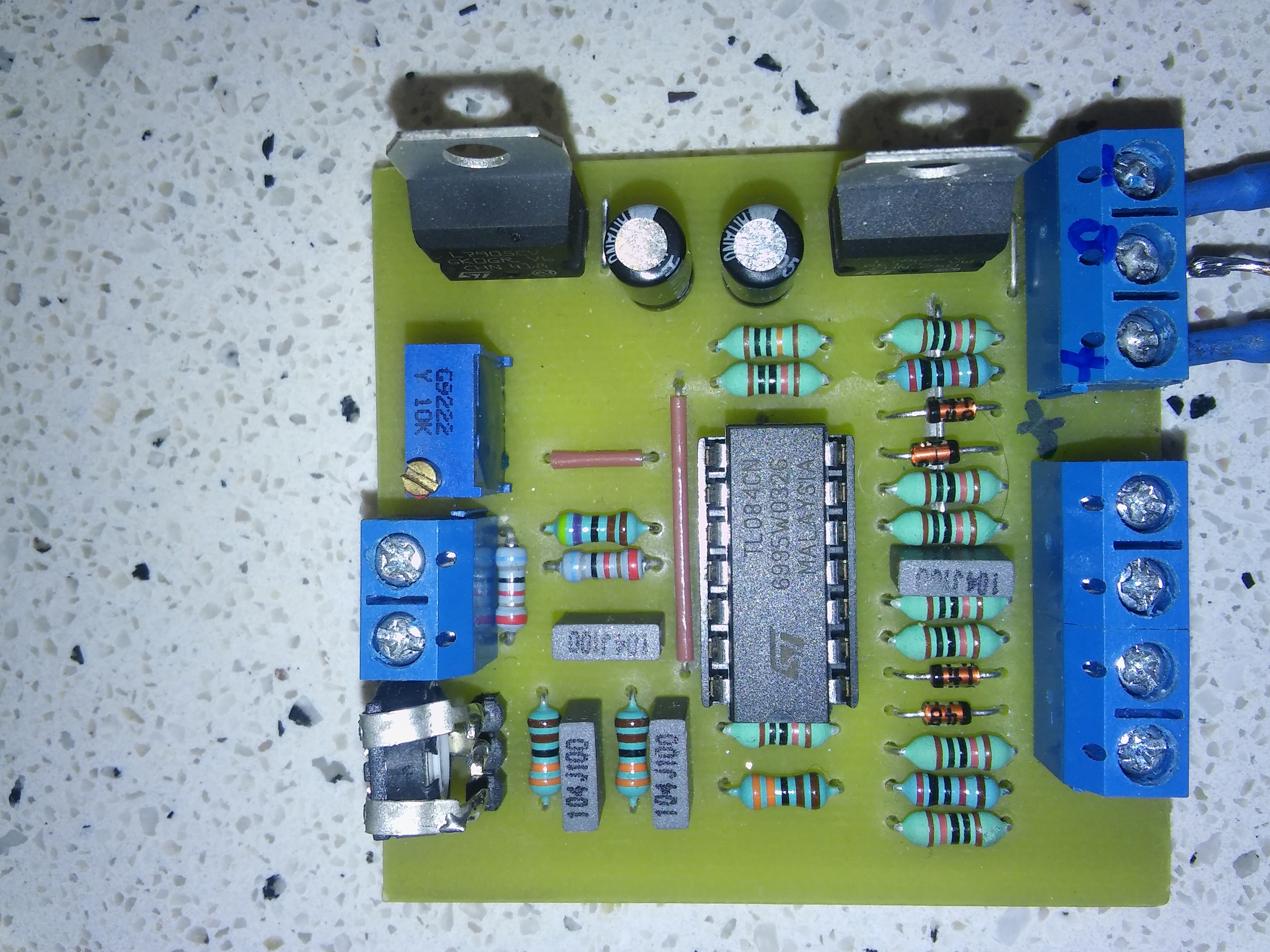 I made a few measurements with it, but it wasn't accurate enough, there was always some noise in the output DC signal.
Thankfully, I found a spec IC from Analog Devices, called AD598. This IC rocks! It has built-in sine wave function generator for the primary coil (amplitude and frequency of the sine wave can be adjusted using resistors and capacitors), the DC output can be adjusted in any interval, and it's very accurate. It looks something like this:
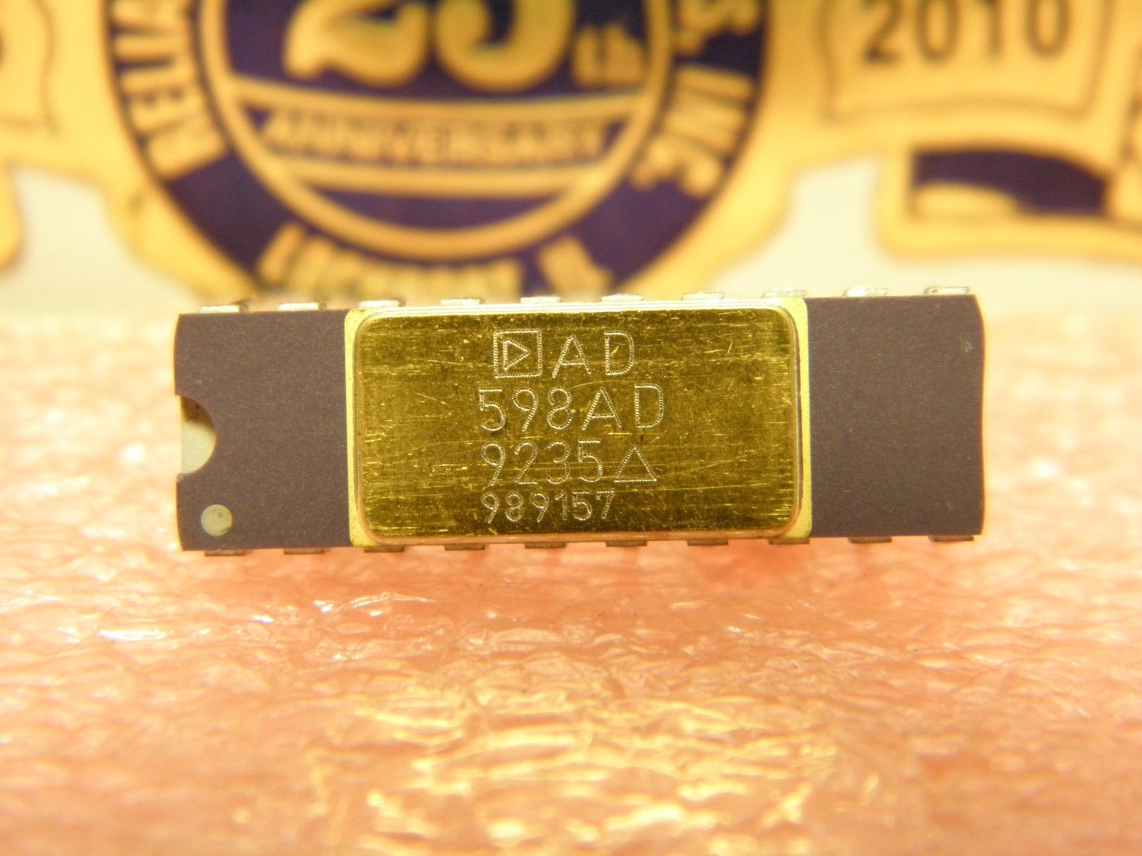
So when I found it, I was very happy, and started making measurements with it - it was a way better and accurate. The diagrams posted above all came from measurements based on this IC.