Close
0%
0%

USB Multimeter

All in one open source device to monitor and data log power usage of USB devices and other connection types.

Similar projects worth following
The USB Multimeter is a full featured all in one device that measures current, voltage, wattage and power consumption using an easy to read color LCD touchscreen display. Always frustrated by having to splice cables and clipping probes to wires to measure current, I am designing this multi-channel meter with multiple connector types that can simplify the process of measuring current.

This new tool aims to be a complete overhaul of my previous design, the USB Tester to overcome lack of flash space and limitations of its display to allow for a greatly enhanced feature set with expandability.

GOALS
To build a highly useful current measurement device with built-in connector types
Make UI smooth + easy to use via touchscreen
Measurement range from microamps to 3A+
kHz sampling rates
Various options with multiple channels
Make it durable with 3D printed enclosure
Make it modular
Multiple data logging/control interfaces
Integrate with apps like

The USB Multimeter is a multi-channel meter with multiple connector types so you can easily place it inline with your current source. The data is graphed in real time on the LCD display, streamed over USB/BTLE, and can be logged to a SD card. The meter is fully configurable from the display or over USB/BTLE.

Hardware:

The USB Multimeter core is powered by the STM32F429 with 2MB of flash for a rich graphical environment. Running at 180Mhz allows for fast sample capture while running the system. I am currently and will be using the following hardware features as well...

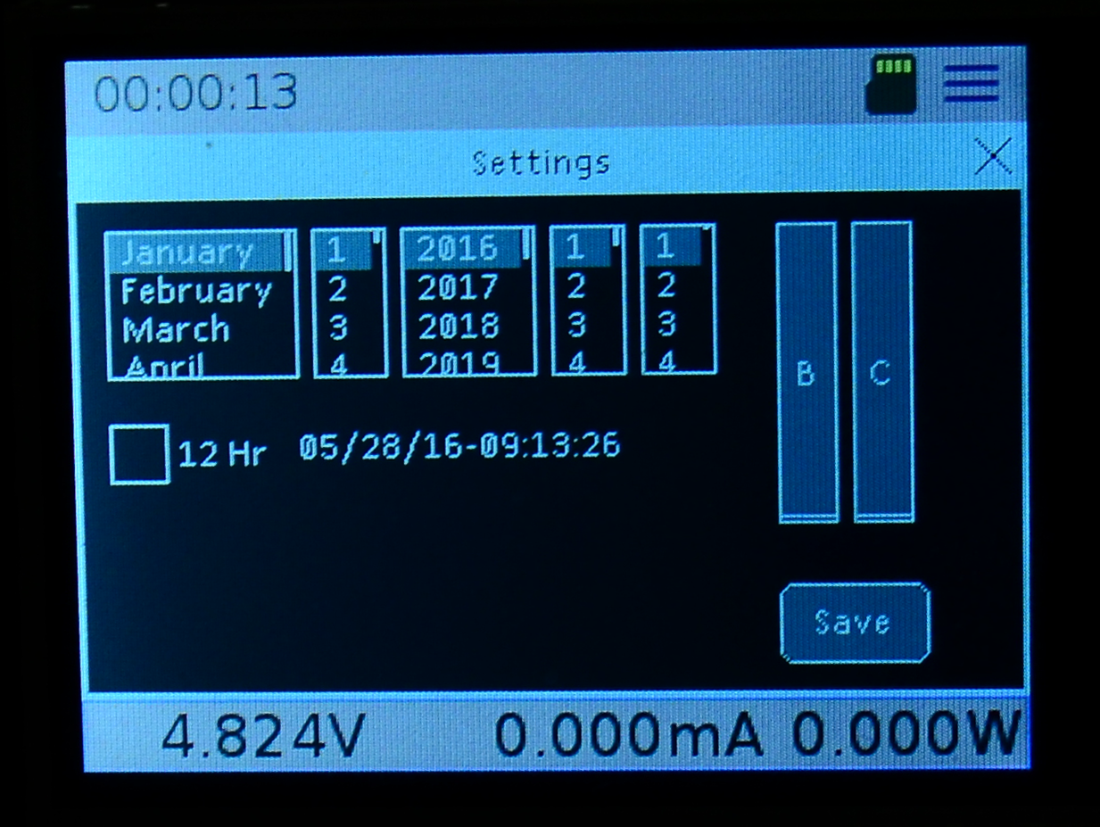
  • RTC for tracking elapsed time and timestamp for data logging
  • Data logging to SD card and USB/BTLE
  • USB data line control (allow power connections only), securing your device from a malicious source.
  • USB 3 - A to MicroUSB 3 which supports USB 2 Micro USB.
  • USB Type-C
  • DC Jack 5.1mm, center positive
  • Screw terminals
  • Test points for connecting your own probes (o-scope, etc)
  • USB Passthrough is routed with differential pairs to maintain signal integrity
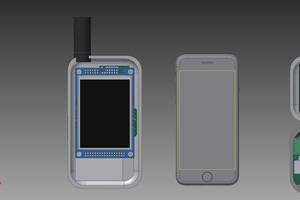
  • Color LCD Resistive Touchscreen (final version will have capacitive touch)
  • 3 channel sensing with Ch3 being a low current channel
  • Possible use of INA219, INA226 and/or INA333 with external ADC
  • RGB notification LED user configurable

Software:

Running ChibiOS allows for flexibility in add many features while maintaining timing within the system. ChibiOS makes it easier to take advantage of many of the hardware features of the STM32F429. ChibiOS also provides a command shell for flexible device control.

Graphics is handled by the uGFX library which gives many options to create a modern easy to use interface in a small memory footprint.

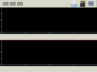
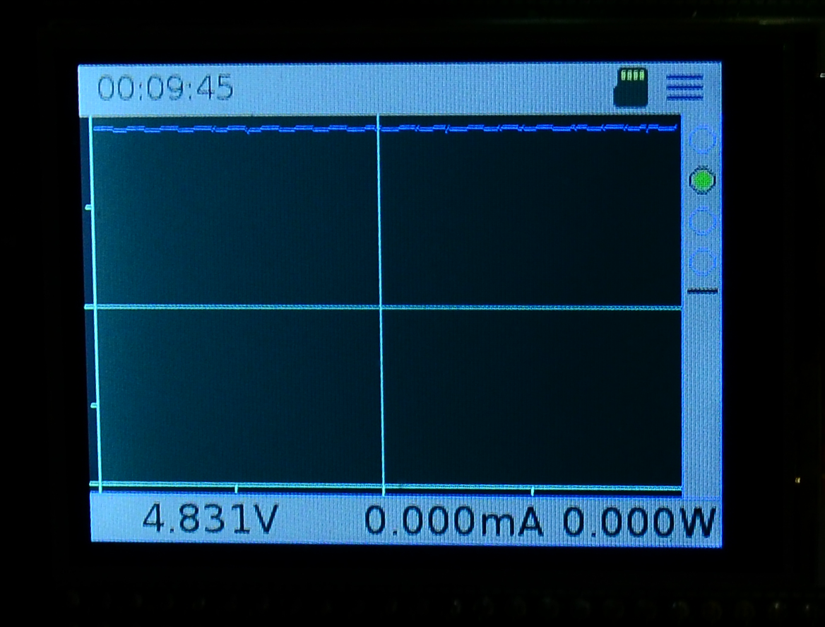
Consisting of multiple graphs, the graphs examine different data points and auto scale based on the displayed data set. The data can be viewed in real time on your desktop or mobile phone by installing the application, Wizkers. Wizkers provides an easy to use graphing interface for remote device control and logging. Visit Wizkers.io for more information.

The top section of the display contains an always visible status bar. Displays time elapsed, current channel selected, and status indicators for USB and SD Card with a menu icon on the right. Each status indicator is selectable for more information and options for that status. For example, the SD card will give the status, size, space free and option to open the file browser.

The menu opens up a dialog to configure the device. This includes setting the time for the RTC and control of the USB data lines, with more options to come.

9d36dd23cbbfa86df0fefb9d244c0f92.png

Rear OSHPark Rendering

Portable Network Graphics (PNG) - 46.34 kB - 05/29/2016 at 18:55

Preview
Download

8519e57fc76967eba4ae961f730cf241.png

Front OSHPark Rendering

Portable Network Graphics (PNG) - 93.12 kB - 05/29/2016 at 18:55

Preview
Download

USB_Tester_STM32F429-DISC1-Sch-4.png

Bluetooth and SD Card

Portable Network Graphics (PNG) - 52.91 kB - 05/29/2016 at 18:54

Preview
Download

Portable Network Graphics (PNG) - 97.47 kB - 05/29/2016 at 18:54

Preview
Download

USB_Tester_STM32F429-DISC1-Sch-1.png

Headers for STM32F429 Discovery Board

Portable Network Graphics (PNG) - 87.62 kB - 05/29/2016 at 18:54

Preview
Download

View all 8 files

  • 1 × HM-11 BTLE Radio
  • 1 × 10k Resistor (pullup)
  • 2 × 0.1 Ohm 1% Shunt Resistor
  • 1 × 2.2uF Capacitor for Regulator
  • 1 × 1.0uF Capacitor for Regulator

View all 17 components

  • Graph Widget

    MobileWill05/29/2016 at 18:43 0 comments

    Currently the graph is made up of an bitmap (converted into an array) that contains the axis and tick marks to divide up the axis. To speed up graph redraw performance, I had used a bitmap converted to an array and then take the previous value and reset that pixel from the bitmap array and then draw the new point. This worked very well over redrawing the entire graph.

    I wanted to make the graph data that is displayed configurable by the user. Originally (as seen in the pictures), the graph has four radials on the right side. The fourth being a split screen graph. The problem lays in where to put the data for the second graph? I could overlay it. but that takes away from the graph data. So I think the way to go is to remove the low info bar and then each graph (top and bottom) will have its own info bar. It is hard to cram all of the needed info for the user in a small screen and still be easily viewable. I wish I could find cell phone displays readily available. The final version will most likely be a capacitive touch display. Then to configure the graph you would just tap the graph. Here is a mock up of what I was thinking.

    It would be a self contained widget with properties you can set, being able to push data to it. They will auto scale on the y-axis and possibly have the option for the user to force the scale if needed. They key is going to optimize for faster refresh rates which is one of my goals. The ability to select which graph is on top and bottom allows you to compare various data points.

    Here are the graphs I am thinking of including, at least initially.

    Current, Voltage, Wattage, mAh, and mWh.

    There still needs to be a place for other data such as peaks, mins and consumption. Once this is complete I can expand upon features such as building out the SD card data logging options and the serial command interface.

  • New Bug

    MobileWill05/29/2016 at 06:41 0 comments

    It seems with the new status bar on top the info bar at bottom has stopped updating. Very strange. The bottom is still made of up a container with textboxes. In thinking through the next design steps it didn’t make sense to spend time on fixing this issue since the graph needs to be converted into a widget and will change the bottom info bar.

  • New Status Bar Widget

    MobileWill05/29/2016 at 06:37 0 comments

    In an effort to streamline the interface, code, and improve performance I have been working with uGFX support to make some major improvements before moving forward with features. One of their suggestions is to make the status bar at the top a widget instead of layered objects. Currently it was a container with a textbox, four buttons and three images of which two are indicators. The buttons actually were using images as well. Working with support, a widget was created that acts as an object with properties that can trigger events. Much better and cleaner in code.

    Here is a picture of the first test with it.

  • Bug fix

    MobileWill05/27/2016 at 06:23 0 comments

    Bug fix: I had an issue where when you open the settings frame it would crash just before drawing the text on the save button. I have been ignoring it for awhile but finally sat down to take a look. Fortunately, after thinking it through it didn’t take much time to find the reason for it. Apparently the font I was loading for the save button and time display was set to a font that hadn’t been loaded in memory first. Doh! If you have used uGFX this will make sense. You have to open the font first before you can use it. Then you can set it as the default or set the font for an object.


    Here is a pic of the offending code. I am not certain what font it is with the _u since that isn’t listed in the list of available fonts. I must of got it from somewhere though...

    Here is the working settings dialog

View all 4 project logs

Enjoy this project?

Share

Discussions

[deleted]

[this comment has been deleted]

MobileWill wrote 05/19/2016 at 16:21 point

Please stop spamming people's projects. 

  Are you sure? yes | no

Similar Projects

Does this project spark your interest?

Become a member to follow this project and never miss any updates