 Alex
Alexsee #192:LED redesign for ongoing work on successor
192:LED
The goal of this Project is to build a very tiny 8x8 RGB LED Matrix. This Matrix will be controlled by UART and/or i2c (not decided yet). Beside this there will be some "demo-Modes" for a standalone operation. The PCB for the LEDs and the firmware of the used Microcontroller are part of this project. There will be also documentation available about the the protocol used to control this Matrix.
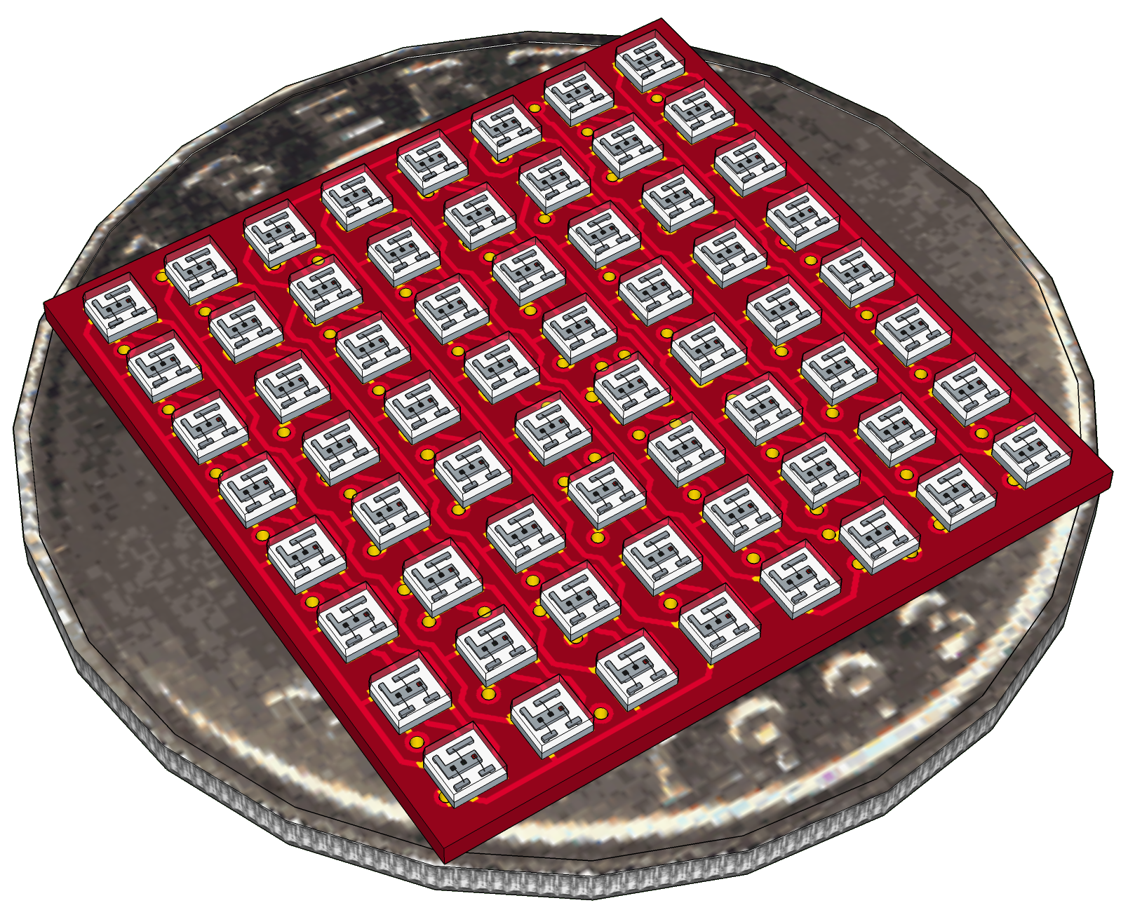
[Image: Rendered project idea on a US quarter Dollar coin. made with sketchup]
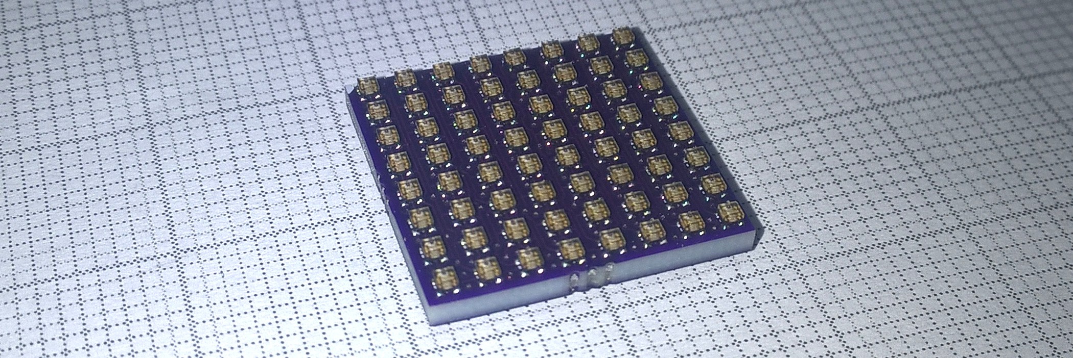
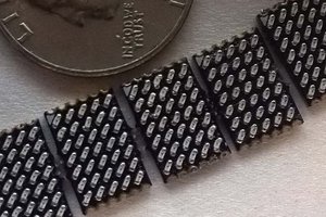
For another of my projects ( #384:LED) I did order the wrong LEDs. So I do have now some of these tiny 0404 RGB LEDs left over:
These LEDs and my wish to design a four Layer board was the motivation to start this project. On the board there will be at least a microcontroller to control all LEDs and perhaps some other stuff to make it smarter.
Hardware
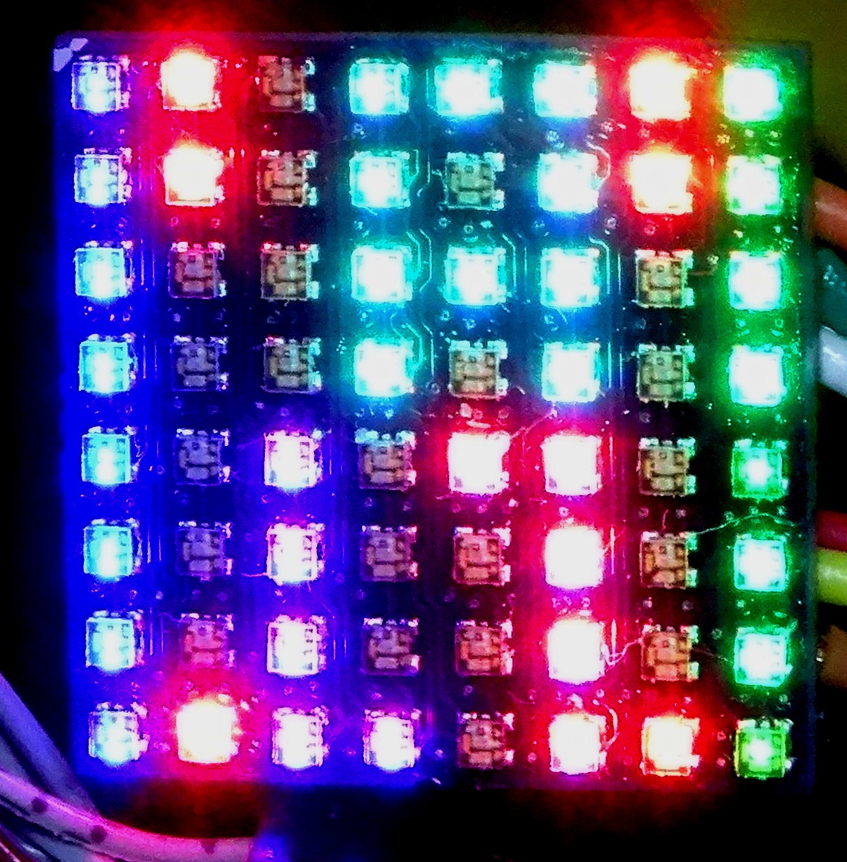
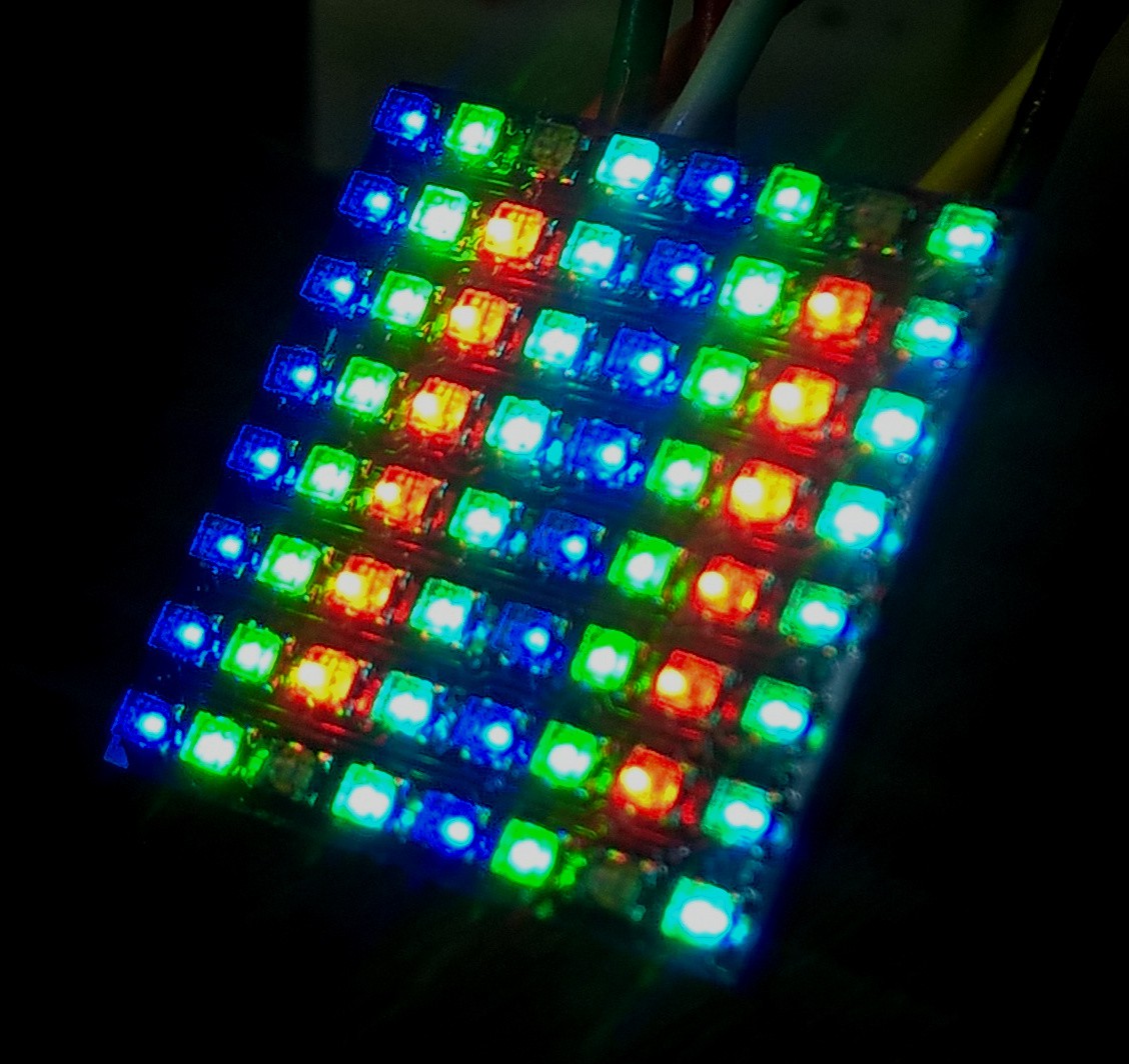
To control all 192 LED chips individually I use normal multiplexing. The Matrix is divided into 16 row with 16 (=3*4) columns. Both a directly connected to the Microcontroller (yes I know this is NOT the best way, but very space effective). There is also no current limiting for the LEDs so the on pulses are to be short.
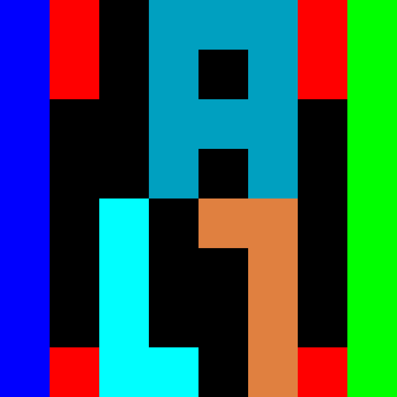
As mentioned the Matrix is organize in 16 lines and 4 columns. The order of the columns are inverted for the lower half of the rows. In the following figure you can see how the physical 8x8 Matrix is mapped.
Organisation of pixels [ROW, COL]:
[0,0] [0,1] [0,2] [0,3] [ 8,3] [ 8,2] [ 8,1] [ 8,0]
[1,0] [1,1] [1,2] [1,3] [ 9,3] [ 9,2] [ 9,1] [ 9,0]
[2,0] [2,1] [2,2] [2,3] [10,3] [10,2] [10,1] [10,0]
[3,0] [3,1] [3,2] [3,3] [11,3] [11,2] [11,1] [11,0]
[4,0] [4,1] [4,2] [4,3] [12,3] [12,2] [12,1] [12,0]
[5,0] [5,1] [5,2] [5,3] [13,3] [13,2] [13,1] [13,0]
[6,0] [6,1] [6,2] [6,3] [14,3] [14,2] [14,1] [14,0]
[7,0] [7,1] [7,2] [7,3] [15,3] [15,2] [15,1] [15,0]
This is looking a little Bit strange but made the layouting much easier (or maybe also possible).
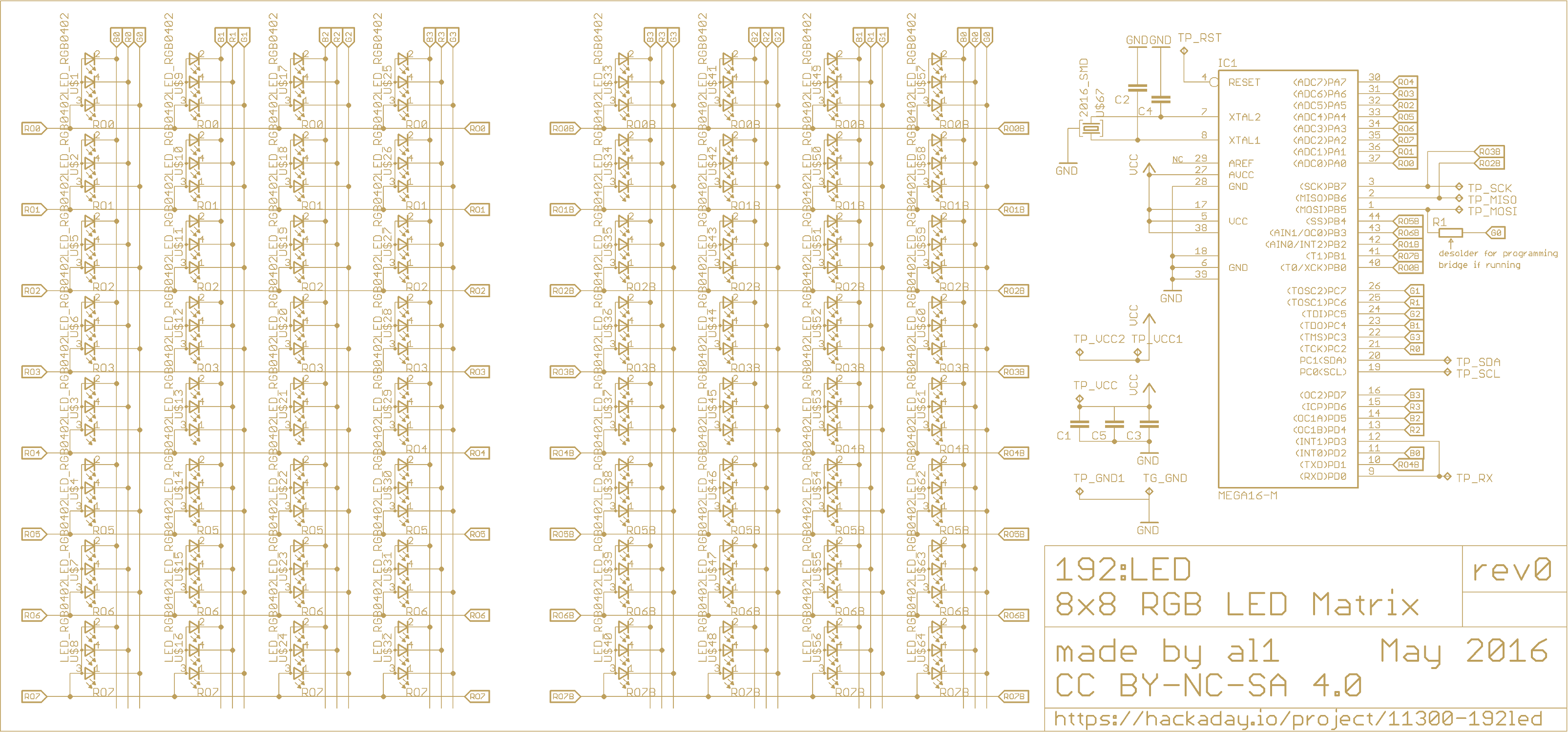
Beside the Microcontroller and the LEDs there are not much more Parts:
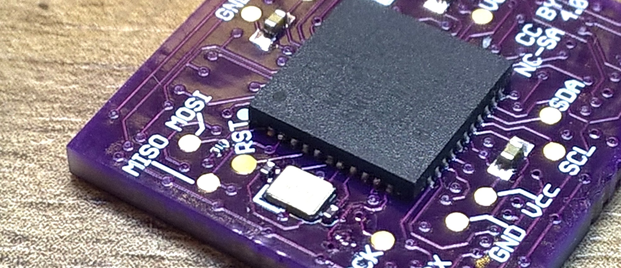
- A 2016 sized Crystal, which can be used if the the internal oscillator is too inaccurate or too slow. There are also two 0201 Capacitors for the Crystal.
- three Buffer Capacitors for Vcc ( all 0402)
- one solder bridge (R1) to disconnect MOSI for programming
Talking about programming: All pins needed for the ISP are break out on test pads. For programming R1 (more a solder bride than a resistor) needs to be open, other wise the Programming signals could drive some LEDs. This could disturb the programming. But with R1 open all programming signal are not connected to anything or just to a cathode of a LED.
PCB Design
The PCB is square with 677,5 mil or 17,2085mm edges. This makes the PCB fit nearly on a quarter US-Dollar coin as seen in the image at the top ( I will also make test with Euro-coins, but there were not available as models in Sketchup). The LEDS are in a 85 mil (~2,16 mm) grid. The dimension are measured in a way that multiple PCBs can get used to built bigger display. On the backside is the microcontroller. I am planning to use a ATmega 16/32 or compatible newer AVR like the ATmega 324.
Interface
I am planing to use UART for controlling this Matrix from some Master Device, but first I will run it stand alone. There are also both pins of the i2c bus as test pads available.
Software
Well, this is still to do....
License
I will publish the whole project under the CC BY-NC-SA 4.0 license. So this project qualifies not as open Hardware as the OSHWA defines it, because I decided to add the NC (=non commercial) tag. I wanted to publish it only for non commercial use. If you would like to use this in any commercial way, please contact me.
Further Information
In the Github repository you will find additional files for this project.
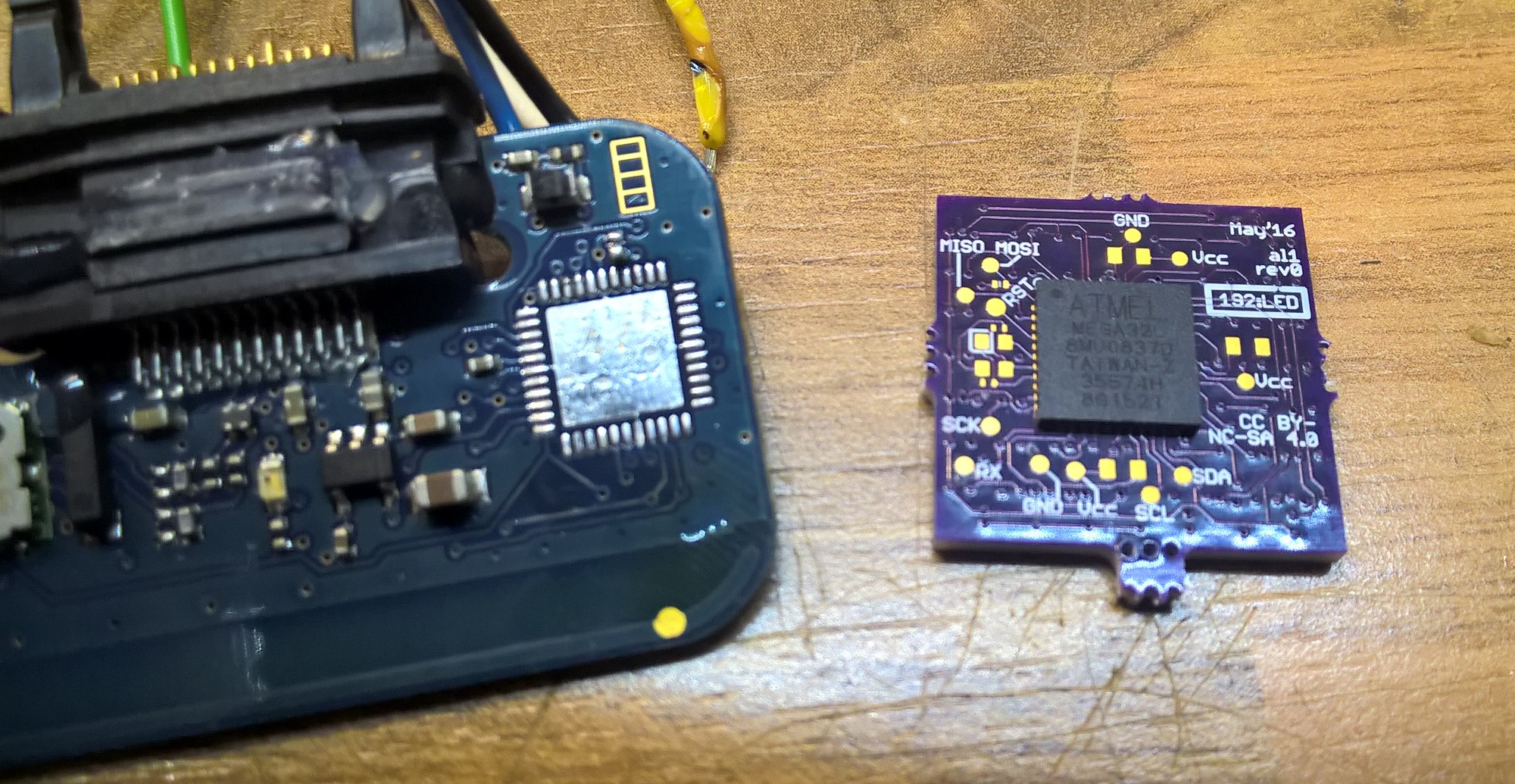 You should only take care about the fuse settings of the controller. I did reprogrammed them to default before desolder the ATmega from the MMR-70 board.
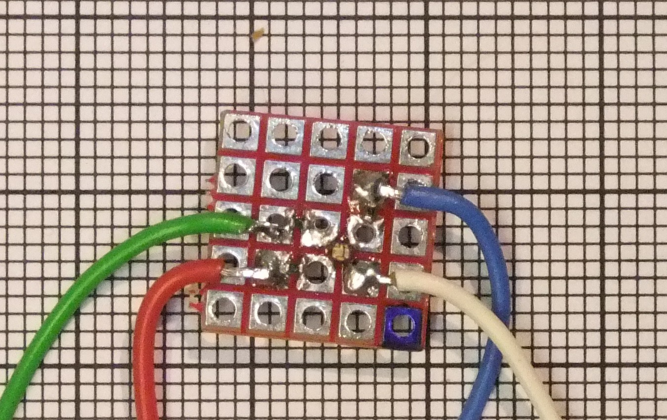
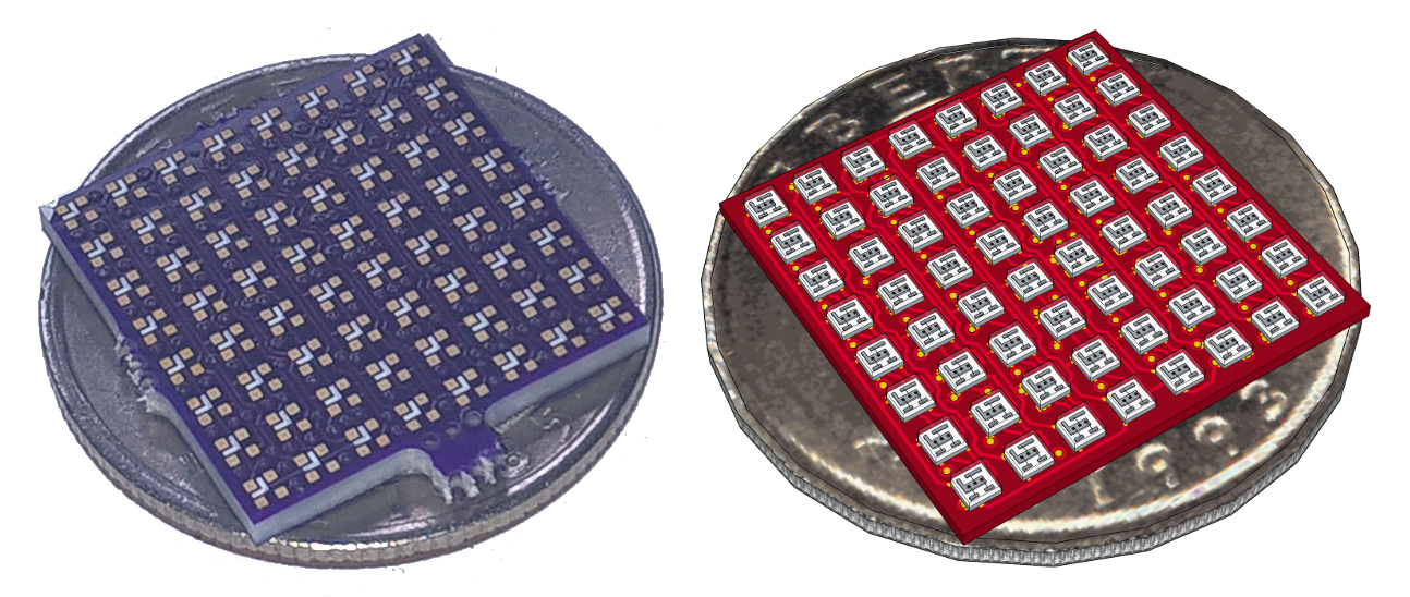 On the left is a photo the right is the rendering. Luckily I found a real ¼US$ coin at home.


 zakqwy
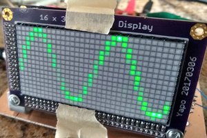
 Ted Yapo
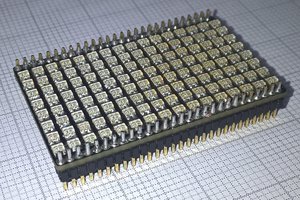
How is the current limiting for the LEDs done?