 Alex
AlexWARNING: This will get some more and complicated...
I did broke out the RX pin on the PCB to get the possibility to sent images over UART to the display. And this is now also working. I also want to offload most of the processing to the UART sender (now just a PC with USB-UART bridge, but later perhaps some master Microcontroller/FPGA) . So I decided to just send the image as it is also coded internally:
- 8 Byte per pixel
- In the byte all three colors like RRRGGGBB (sometimes this is called 8 bit true color, it is not my idea)
- so I need 64 Byte per image
- The Byte order is chosen by me the first byte is the top right pixel an than follow the first line and so on
The UART part was made fast and easy, but getting the needed data was complicated. I found no graphic program which saves images in 8 bit true color. So I decided to script some matlab/octave to that:
function IMG_test

  myImage = imread("image.png");  #read 8x8 pixel image
  # the image is vreatet with MS paint. At least there each
  # pixel is encoded into three bytes (R,G,B) this could be
  # normal for png. At least I hope so

  # now to the conversation magic
  red   = uint8(bitshift(myImage(:,:,1), -5));
  green = uint8(bitshift(myImage(:,:,2), -5));
  blue  = uint8(bitshift(myImage(:,:,3), -5));

  #add the three colors to one byte togehter
  img8trueColor= bitshift(red,5) + bitshift(green,2) + blue;
  #show the reult (just for visual inspection)
  imshow(img8trueColor);
  #transpose the image - needed to save it correctly
  img8trueColor=img8trueColor.';
  myFile=fopen("out.txt", "w");
  fwrite(myFile,img8trueColor);
  fclose(myFile);
  #{
    The out put file now should look like this:
    07 E0 00 1A 1A 1A E0 1C
    07 E0 00 1A 00 1A E0 1C
    07 00 00 1A 1A 1A 00 1C
    07 00 00 1A 00 1A 00 1C
    07 00 23 00 F2 F2 00 1C
    07 00 23 00 00 F2 00 1C
    07 00 23 00 00 F2 00 1C
    07 E0 23 23 00 F2 E0 1C
    The first eigt bytes (first line) are the top line of the
    display also.
  #}
endfunction
This small script is some kin of user unfriendly, but working. My workflow now is:
- create some 8x8 pixel image (I used just MS paint)
- save it as png
- store it in the directory of the octave script
- run the octave script
- now you have a 64Byte big file named "out.txt"
- sent "out.txt" with Realterm over the UART to the display ( the file is *.txt because this is the only supported filetype by Realterm)
So now some result and images:
This is my in step 1 created image:
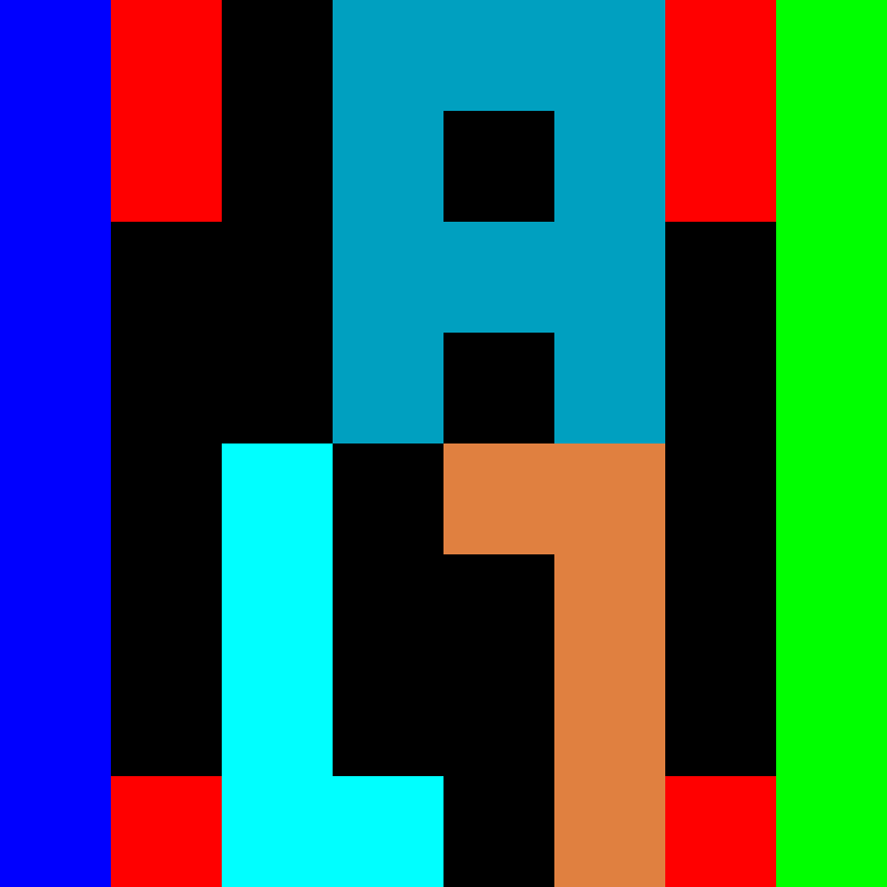
My octave script create me now this file:
07 E0 00 1A 1A 1A E0 1C
07 E0 00 1A 00 1A E0 1C
07 00 00 1A 1A 1A 00 1C
07 00 00 1A 00 1A 00 1C
07 00 23 00 F2 F2 00 1C
07 00 23 00 00 F2 00 1C
07 00 23 00 00 F2 00 1C
07 E0 23 23 00 F2 E0 1C
00 is black; 07 is blue; 1C is green and so on.....
After sending this to the display the display looks like this:
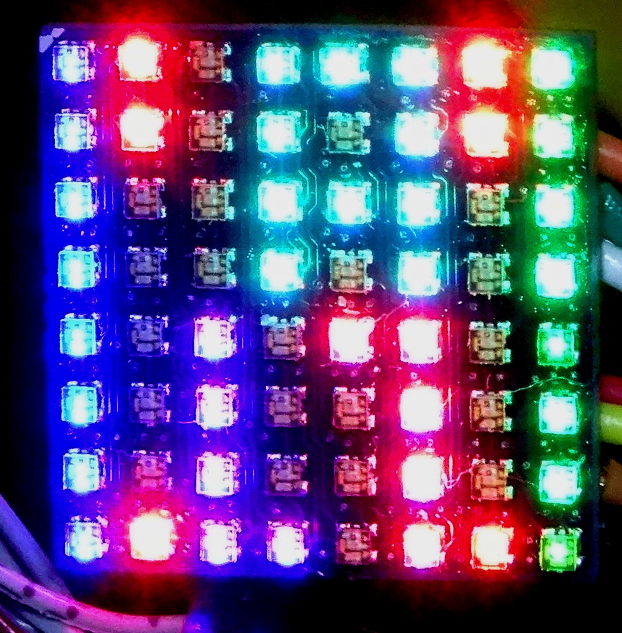
The colors are at least similar as in the original image. Maybe I will add some kind of color correction to the octave script.
So with a fas enough master device, which has lots of (or multiplexed) UART outputs and some more image (or video) software on it, I could now build big displays with this.
Discussions
Become a Hackaday.io Member
Create an account to leave a comment. Already have an account? Log In.