 fabsterdam
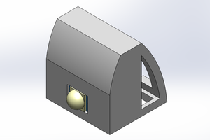
The PICO-8 is a fantasy console to play but also make games with it. It tries to be like the old 8-bit computers with sprite, music and code editor built in. For this project we want to have a small portable console to play with the PICO-8 games anywhere.
The PICO-8 has a Raspberry Pi port so the Raspberry Pi Zero is perfect for this task due to its small size.
It has a 128x128 native resolution so for the PICO ZERO projet we will be using this Adafruit display. That display is ready to be used with an Arduino and Adafruit even provides some libraries for it. Fortunately there is also a kernel module already in raspbian to use this kind of displays which supports the adafruit ones.
I downloaded the latest Raspbian from the oficial site. I am using the [Raspbian Jessi] Lite version since we don't need the X window or any other extra stuff. We will be running the PICO8 directly on start, just after booting.
I first solder the pins to the screen and then wired (temporarly) it to the Raspberry Pi Zero to start using the screen. I followed the wiring scheme described in the wiki for that kernel module (fbtft). If you use a different screen please have a look at the LCD Modules supported section to see how to connect it.
As you can see, our screen is not appearing in there. Ours is 1.44" and 128x128 and that one is 1.8" and 128x160. But both are sharing the same controller: ST7735R. It looks like the 1.88" screen is a more modern version of the other, so for now we are using that configuration.
Once you have connected the screen to the Pi GPIO pins it is time to start configuring it. Again, following the wiki of the FBTFT module, the first thing to do is to load the module with the configuration for your screen. In our case the device name is adafruit18 so in the terminal:
sudo modprobe fbtft_device name=adafruit18If everything is fine you can see the fbtft_device logs in dmesg which look like these:
fbtft_device:  SPI devices registered:
fbtft_device:      spidev spi0.0 500kHz 8 bits mode=0x00
fbtft_device:      spidev spi0.1 500kHz 8 bits mode=0x00
fbtft_device:  'fb' Platform devices registered:
fbtft_device:      soc:fb id=-1 pdata? no
fbtft_device: Deleting spi0.0
spi spi0.0: setting up native-CS0 as GPIO 8
fbtft_device:  GPIOS used by 'adafruit18':
fbtft_device:    'reset' = GPIO25
fbtft_device:    'dc' = GPIO24
fbtft_device:    'led' = GPIO18
fbtft_device:  SPI devices registered:
fbtft_device:      spidev spi0.1 500kHz 8 bits mode=0x00
fbtft_device:      fb_st7735r spi0.0 32000kHz 8 bits mode=0x00
fb_st7735r: module is from the staging directory, the quality is unknown, you have been warned.
graphics fb1: fb_st7735r frame buffer, 128x160, 40 KiB video memory, 4 KiB DMA buffer memory, fps=20, spi0.0 at 32 MHz
If you happen to see an error saying
ERROR: could not insert 'fbtft_device': Invalid argumentand in dmesg:
fbtft_device: spi_busnum_to_master(0) returned NULL
it means that you have SPI drivers disabled. This is the default configuration in raspbian so you need to run raspi-config to enable it. Or just delete the blacklist from /etc/modprobe.d/raspi-blacklist.conf. This is better explained in this issue on the wiki of the FBTFT module.
I run raspi-config because I wanted to expand the filesystem too. So I enabled SPI from there and the module loaded fine.
Next step is to test that something is shown on the screen. In our case we don't have xserver installed so we need to show the console in there (and not the xserver), This is done by typing the command:
con2fbmap 1 1This maps the console 1 in the framebuffer 1 (our tiny screen). To go back to the HDMI screen you can do:
con2fbmap 1 0For now unfortunately we don't see any image appearing in the screen. It could be that the framebuffer that is creating is bigger than the screen and the screen doesn't like it. I'll try to follow the indications in here to create a "custom" one with the proper size and see if that works.


 Ben Lim
 AIRPOCKET
 Martin Falatic
Totally cool idea, i'd love to be one of the first to buy one of these things.