0%
0%
Megsy? A homebrew Teensy 3++
Creating a double-sized Teensy 3 to allow easy access to the pins that aren't reachable on a breadboard.
 T. B. Trzepacz
Become a Hackaday.io member
Already have an account? Log in.
Just one more thing
To make the experience fit your profile, pick a username and tell us what interests you.
Pick an awesome username
hackaday.io/
Your profile's URL: hackaday.io/username. Max 25 alphanumeric characters.
Pick a few interests
Projects that share your interests
People that share your interests

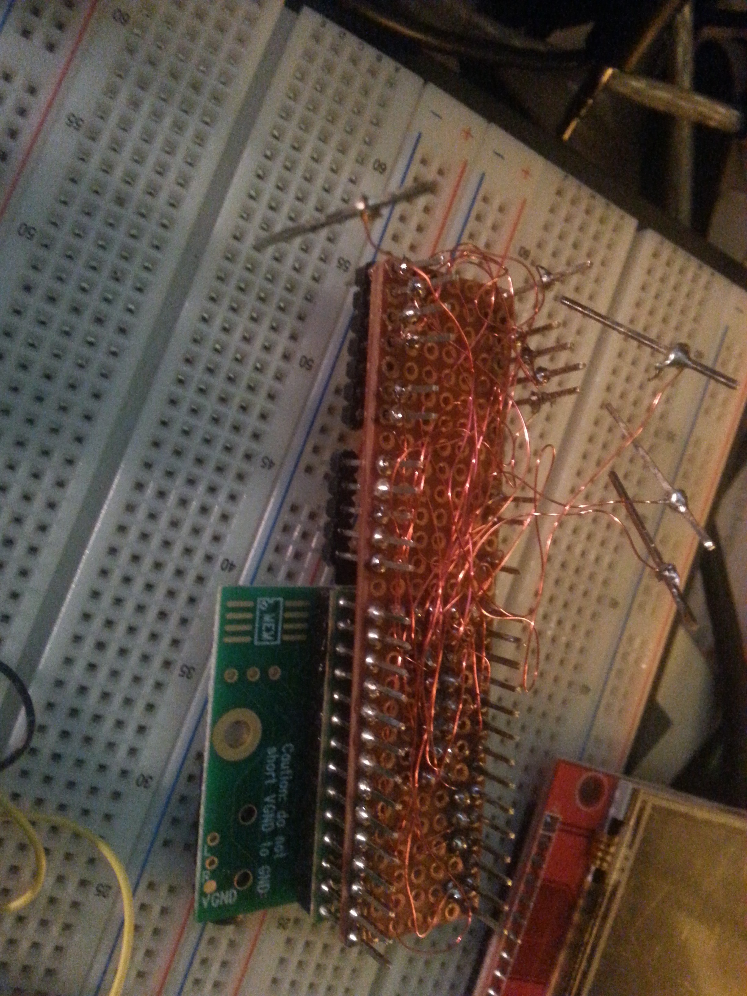
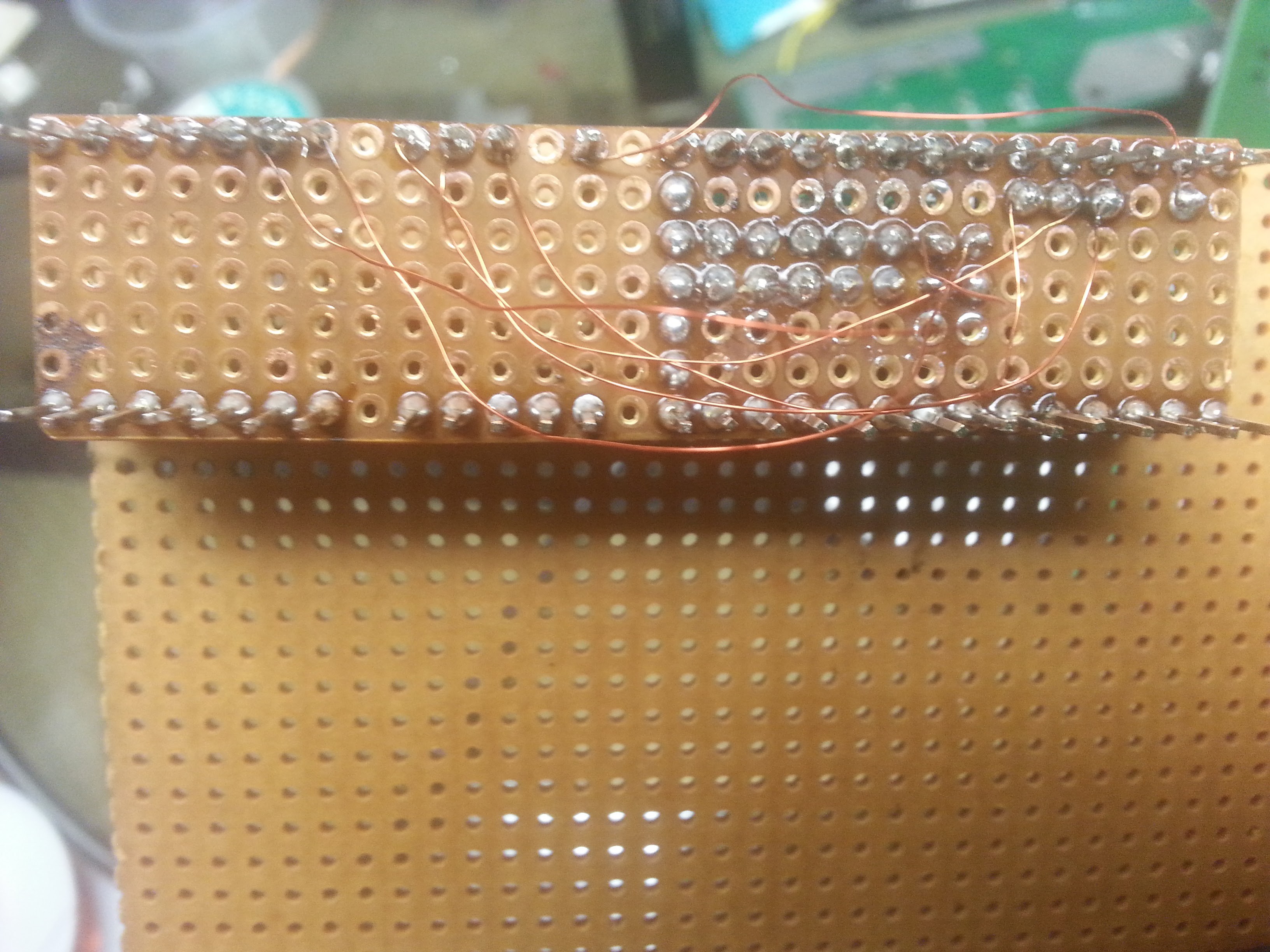
 I watched carefully. It seemed like the solder would bubble for awhile and settle, so I would hold the iron on each pin until the solder stopped bubbling, hoping that was enough time for good flow. A check on the top of the board for some holes that went all the way through shows that the solder did indeed go through the holes on BOTH boards! Bravo!


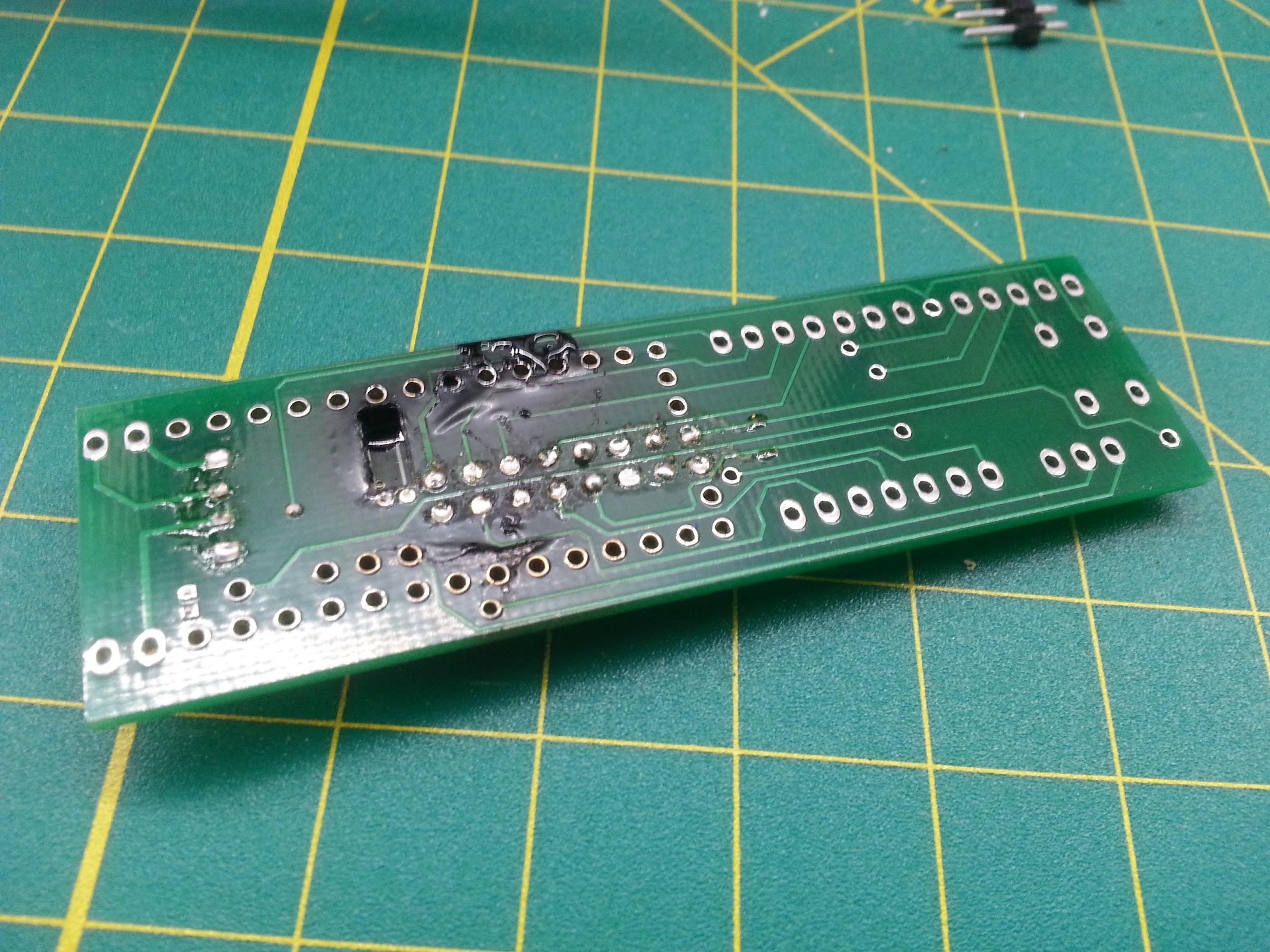
 Or did I?
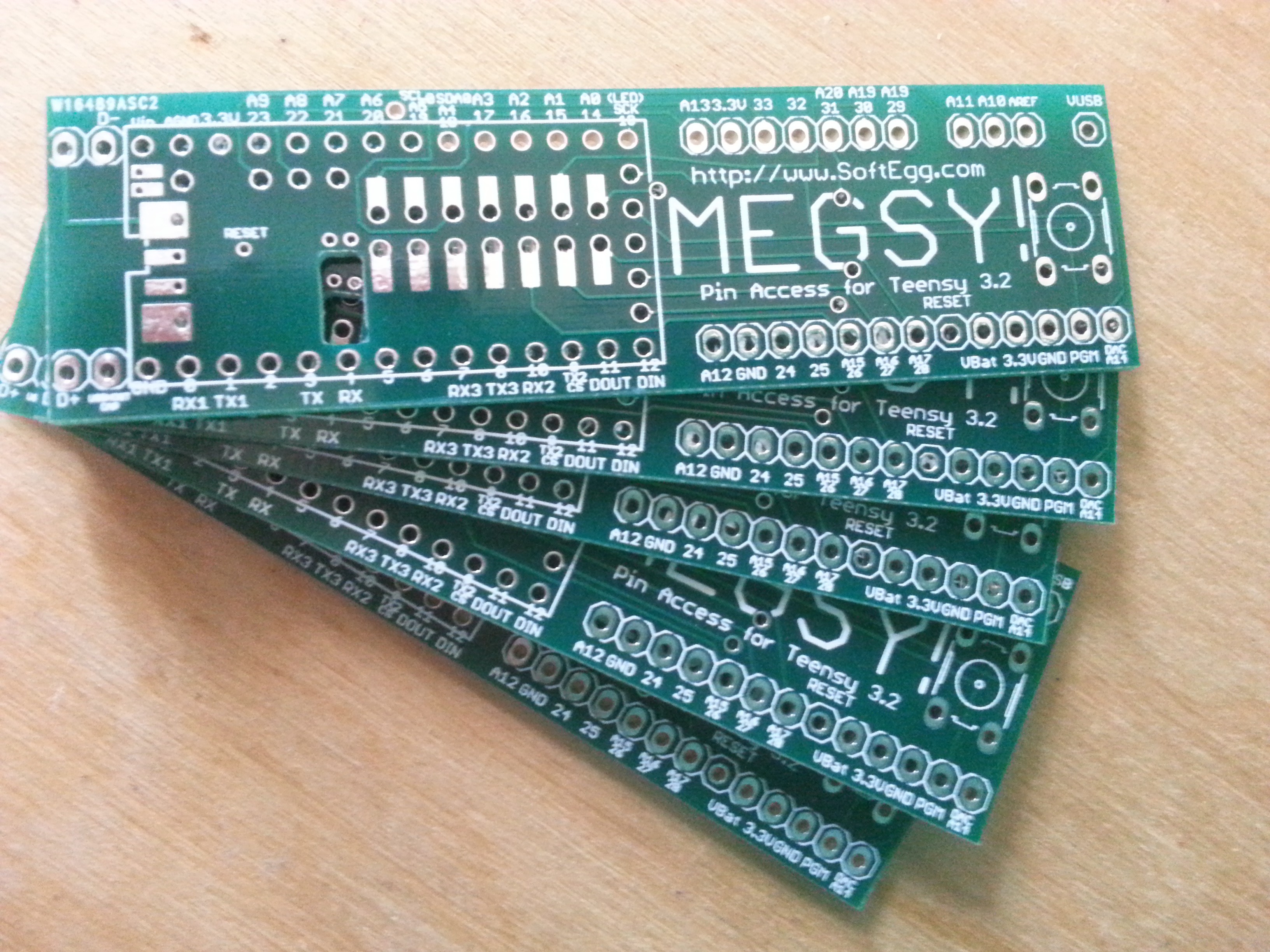


 So I asked about this in the PJRC forums, and evidently Paul has made a board available from OSHPark here:
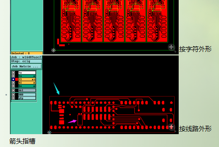
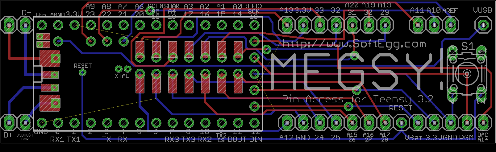
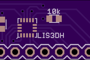
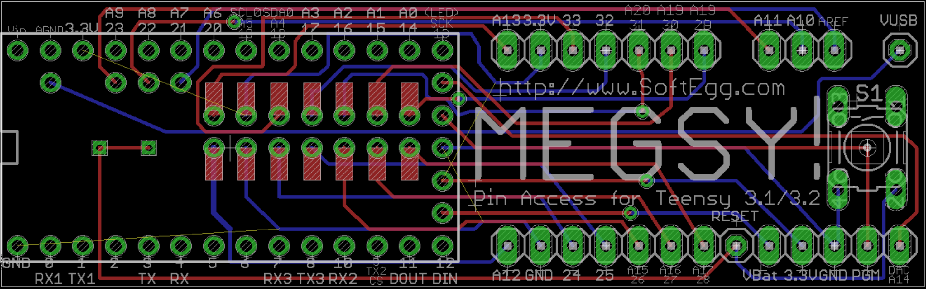 I haven't even really had a chance to use the protoboard version that I soldered up before, but I had a brainstorm and CAD'ed up this PCB.
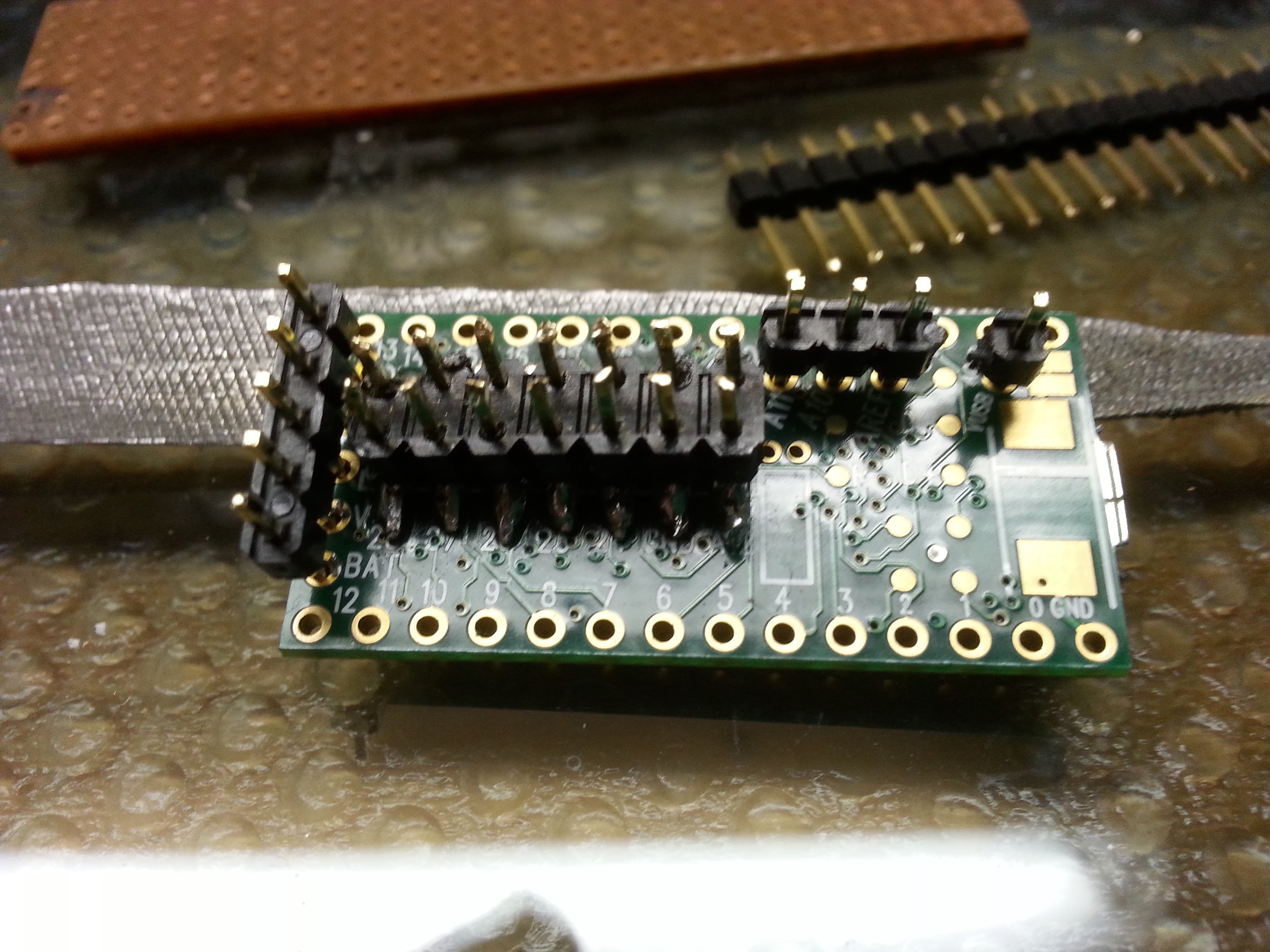
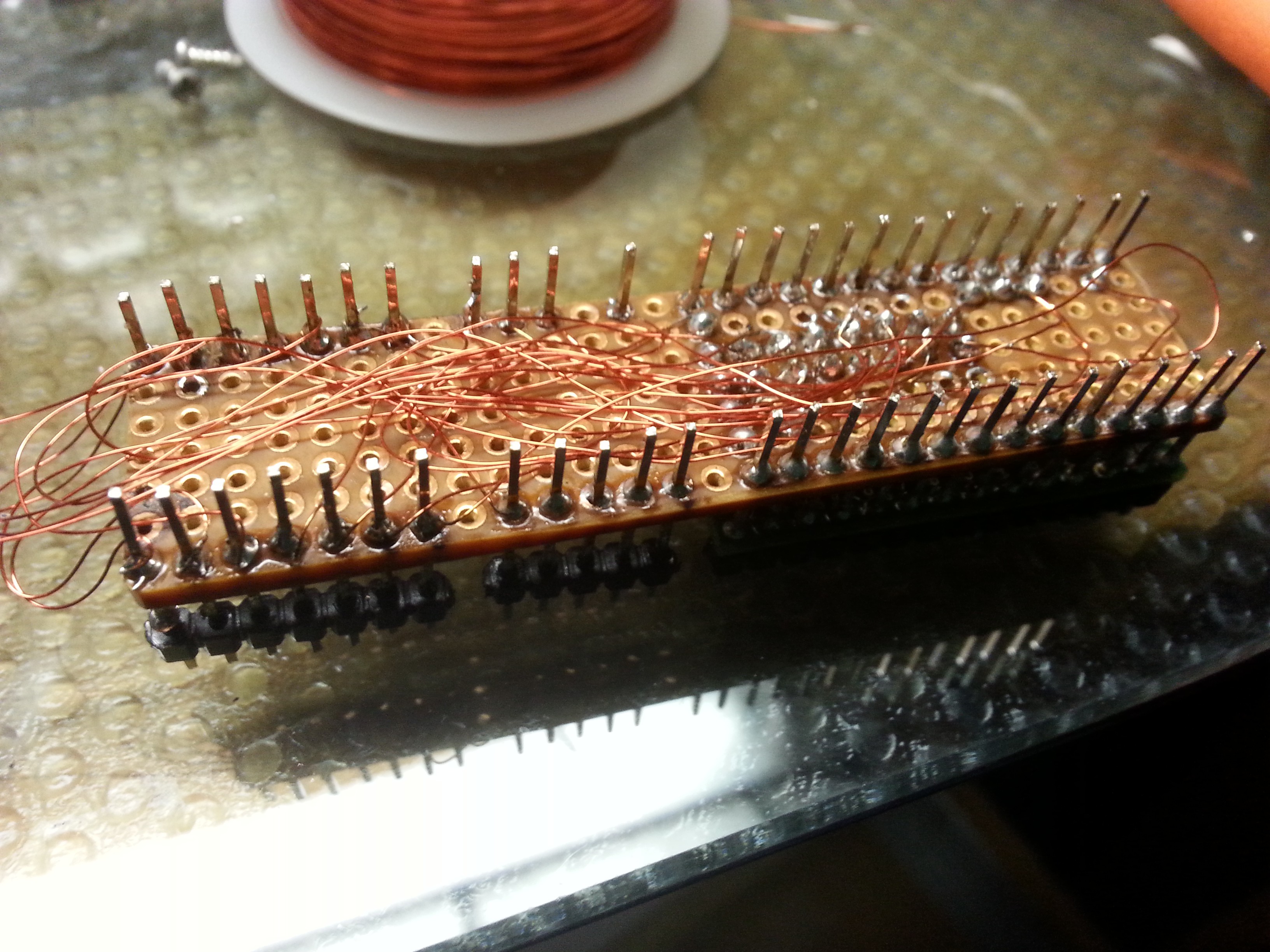
 Christoph
 Dylan Brophy
 Bharbour
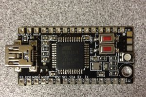
 The Big One