 Joshua Elsdon
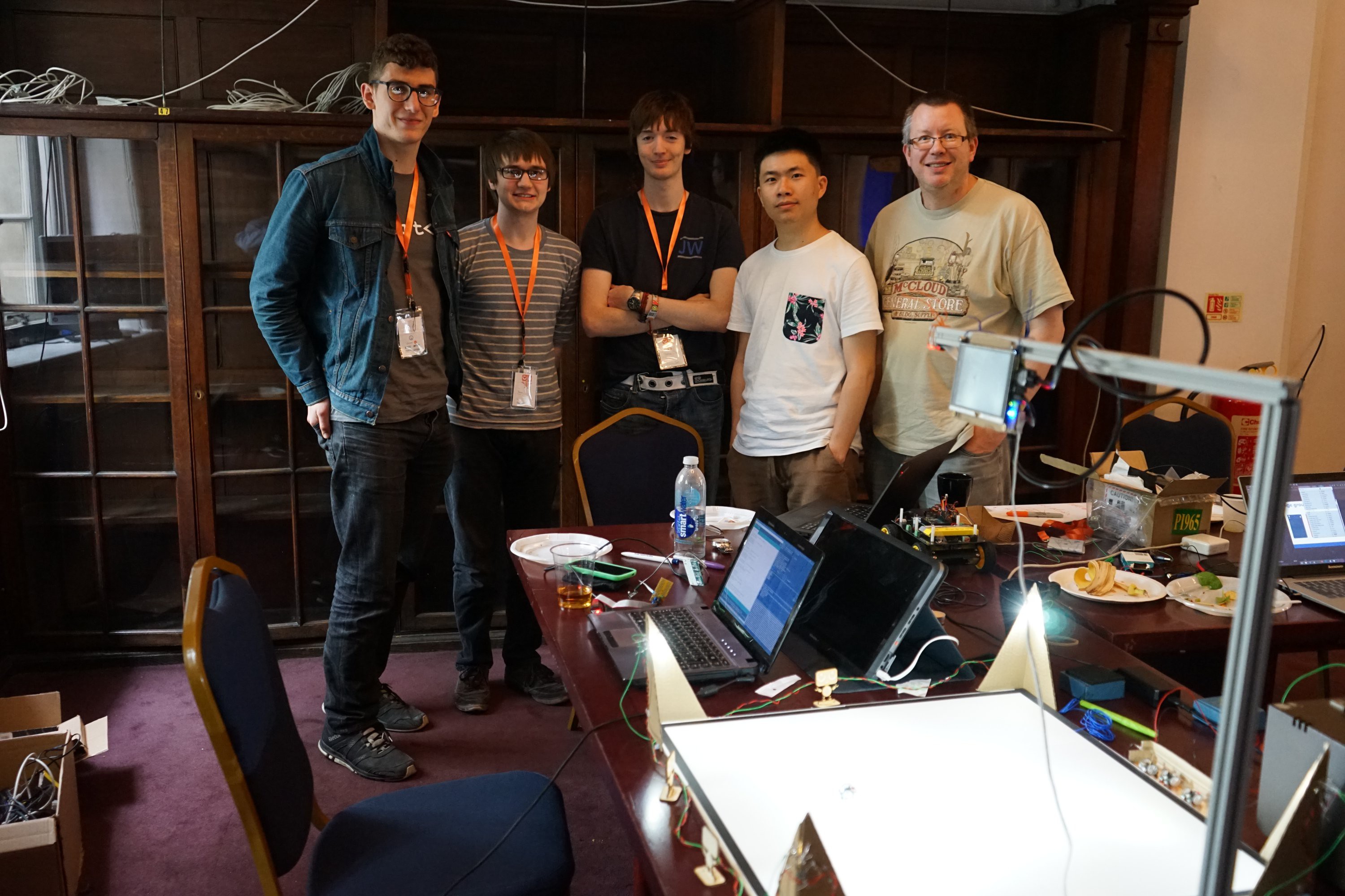
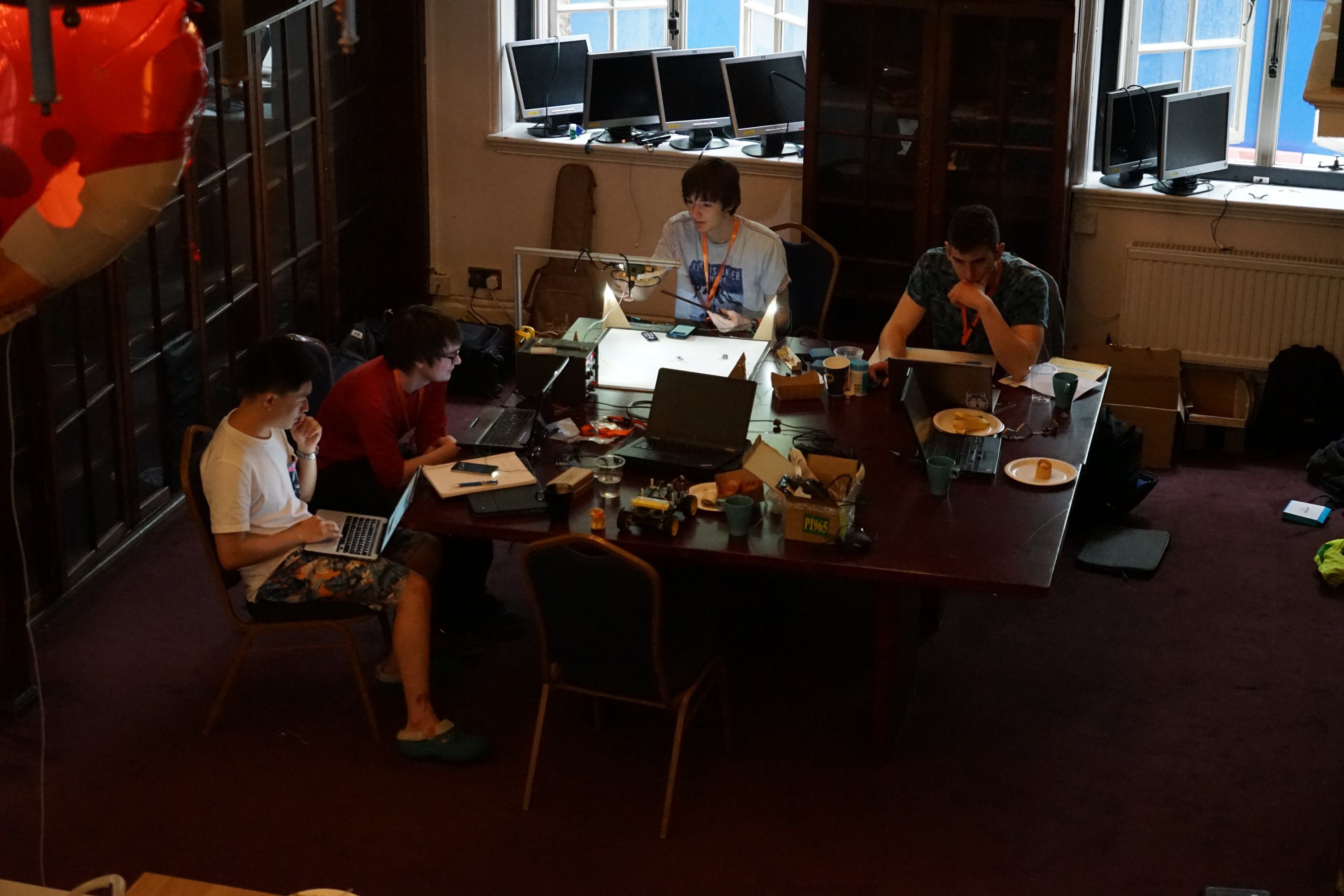
This project spawned from teaching efforts within the Imperial College Robotics Society. We run a very popular course known as 'Robotics 101' which aims to teach students (of University age) the basics of robotics. The hope being we can attract other disciplines (Mechanical engineering, Biology etc) towards being hobbyists in the Robotics world. The issue we observed is that after the course, when the students had their typical A5ish robots completed, it was difficult to then move onto bigger systems. We do have a 102 course within ICRS that tackles multirobot systems, but when each robot is that size, the arena needs to be pretty big, much to the despair of the fire martials (we need to block the fire exit with the arena). Also due to the size and to some extent the cost too, students need to all share the same equipment. We love sharing our stuff of course, but sometimes the thrill of discovery is killed by waiting in line.
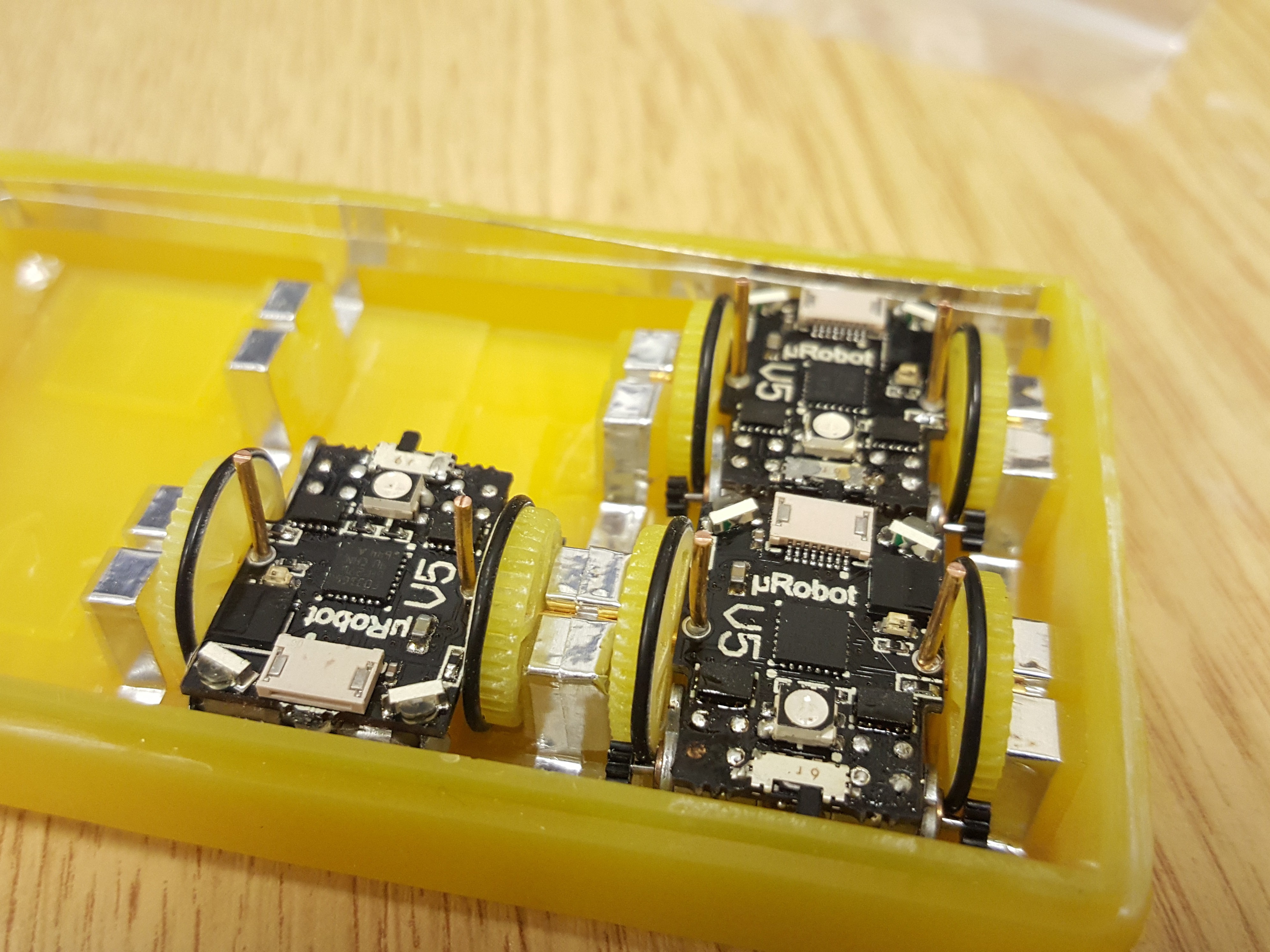
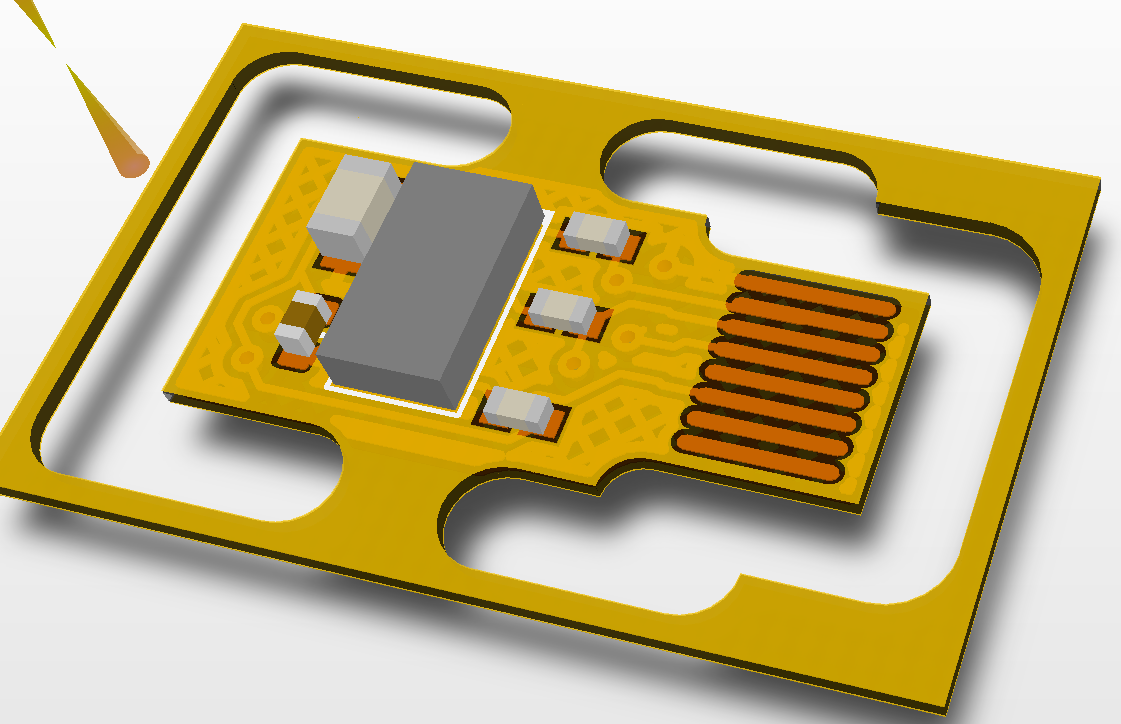
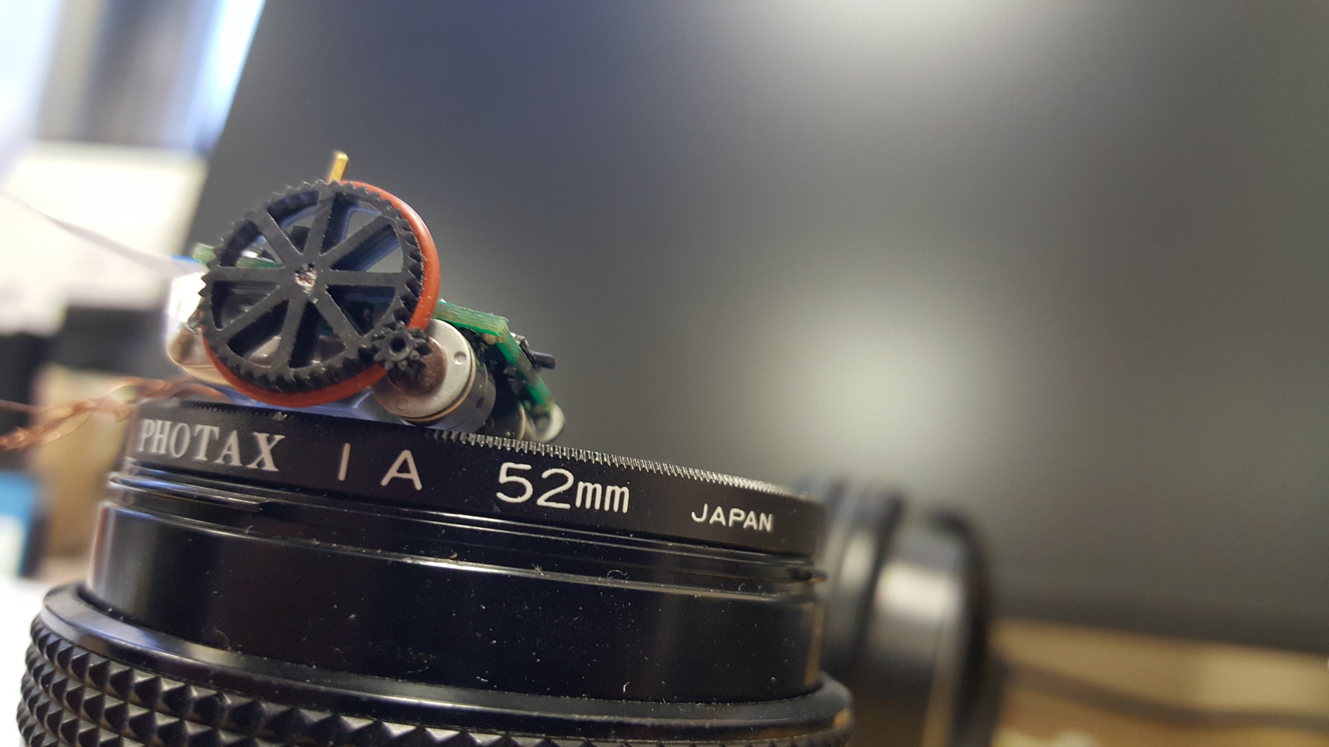
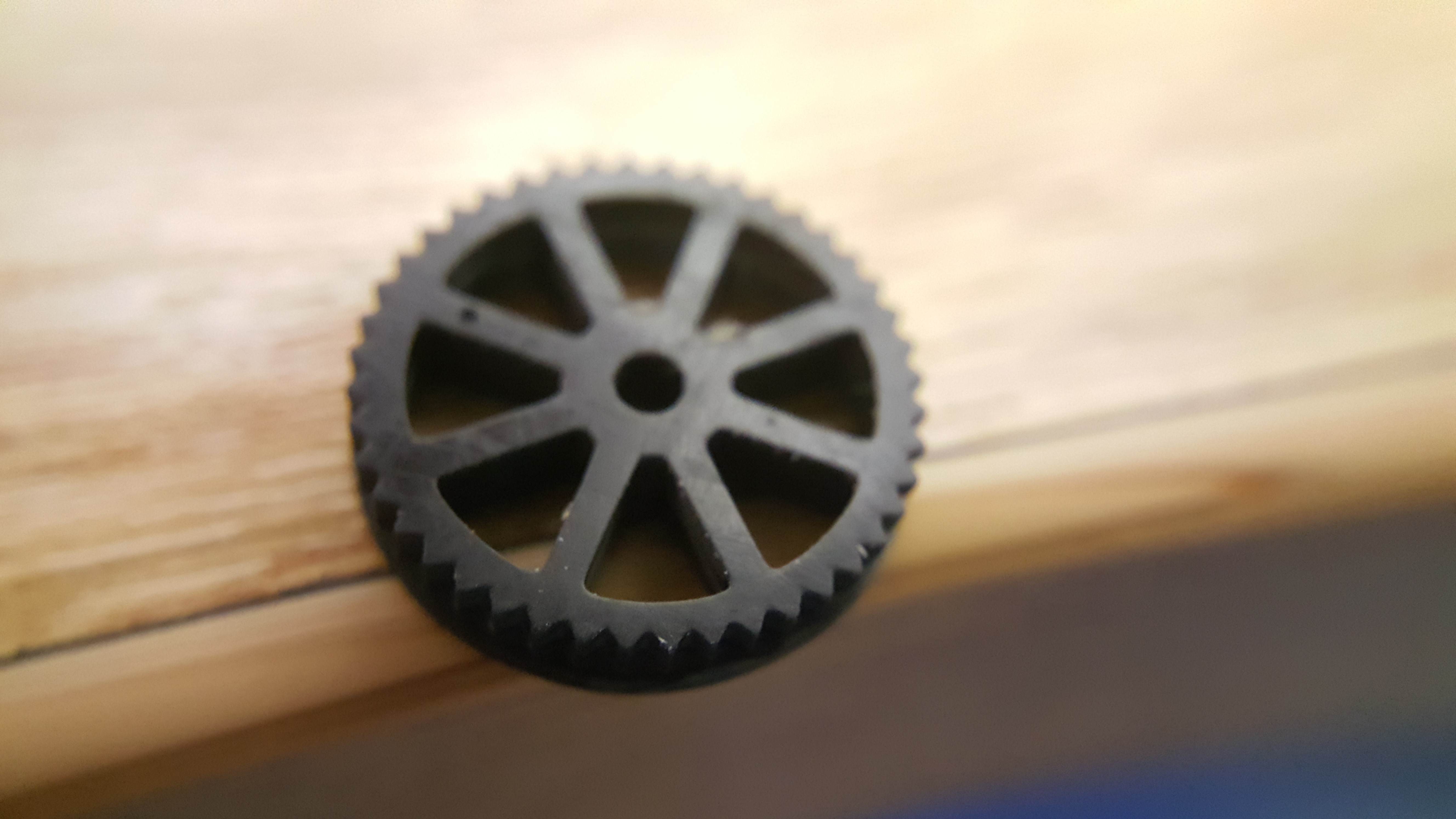
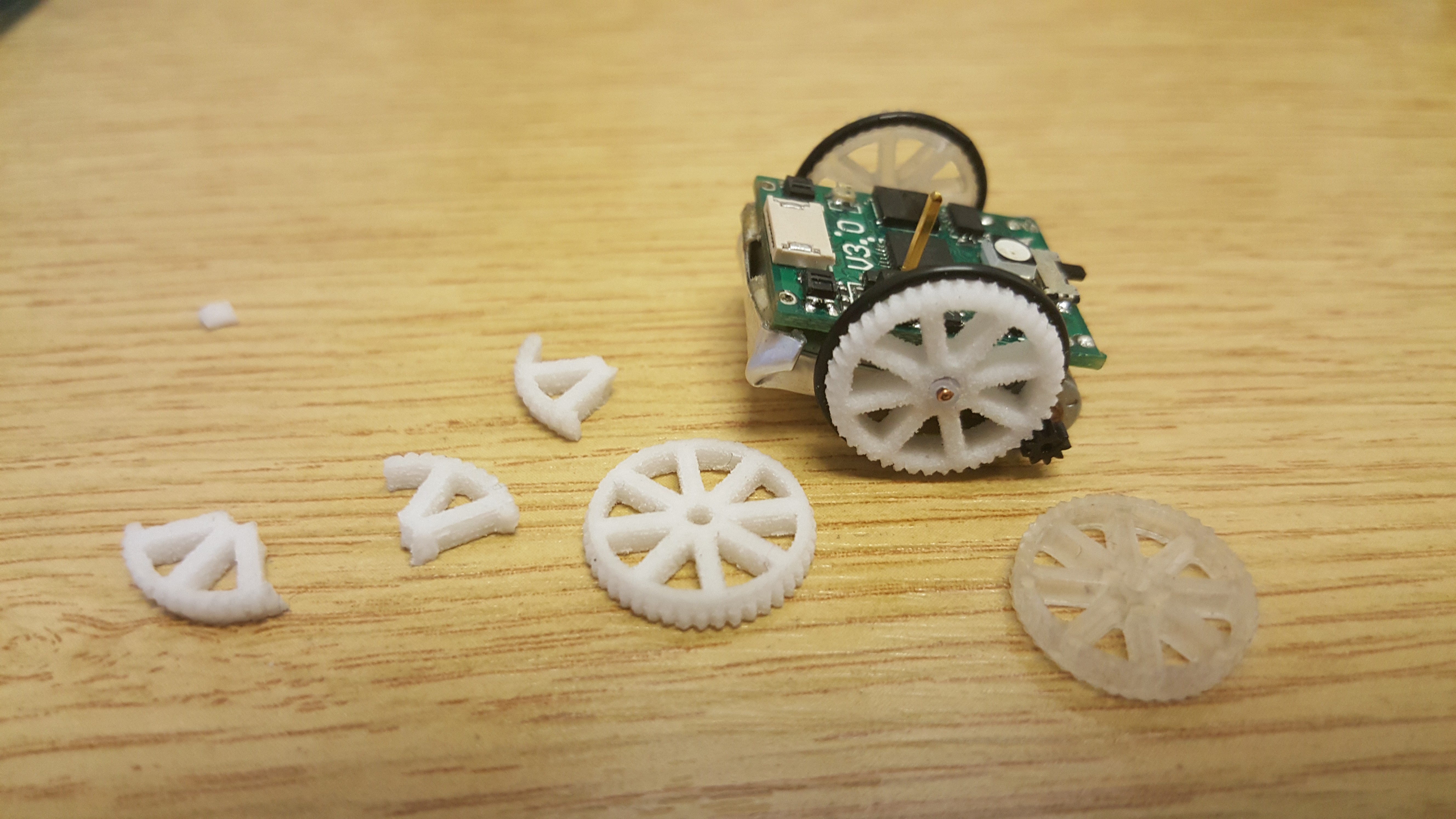
This is where our robots come in! Small enough that a complete multirobot system can operate within the confines of a single desk space, and cheap enough that multiple sets can be deployed per class room. All whilst maintaining the capabilities of your typical 101 robot: Front facing colision sensors, line following sensor, IR uplink and downlink, stepper motor based odometry and RGB indicator LED.
We want students of all ages to see past the typical line following or object avoidance tasks and think bigger. Swarm behaviour, competitive sport, collaborative task solving, having multiple robots at your disposal makes designing these systems possible.
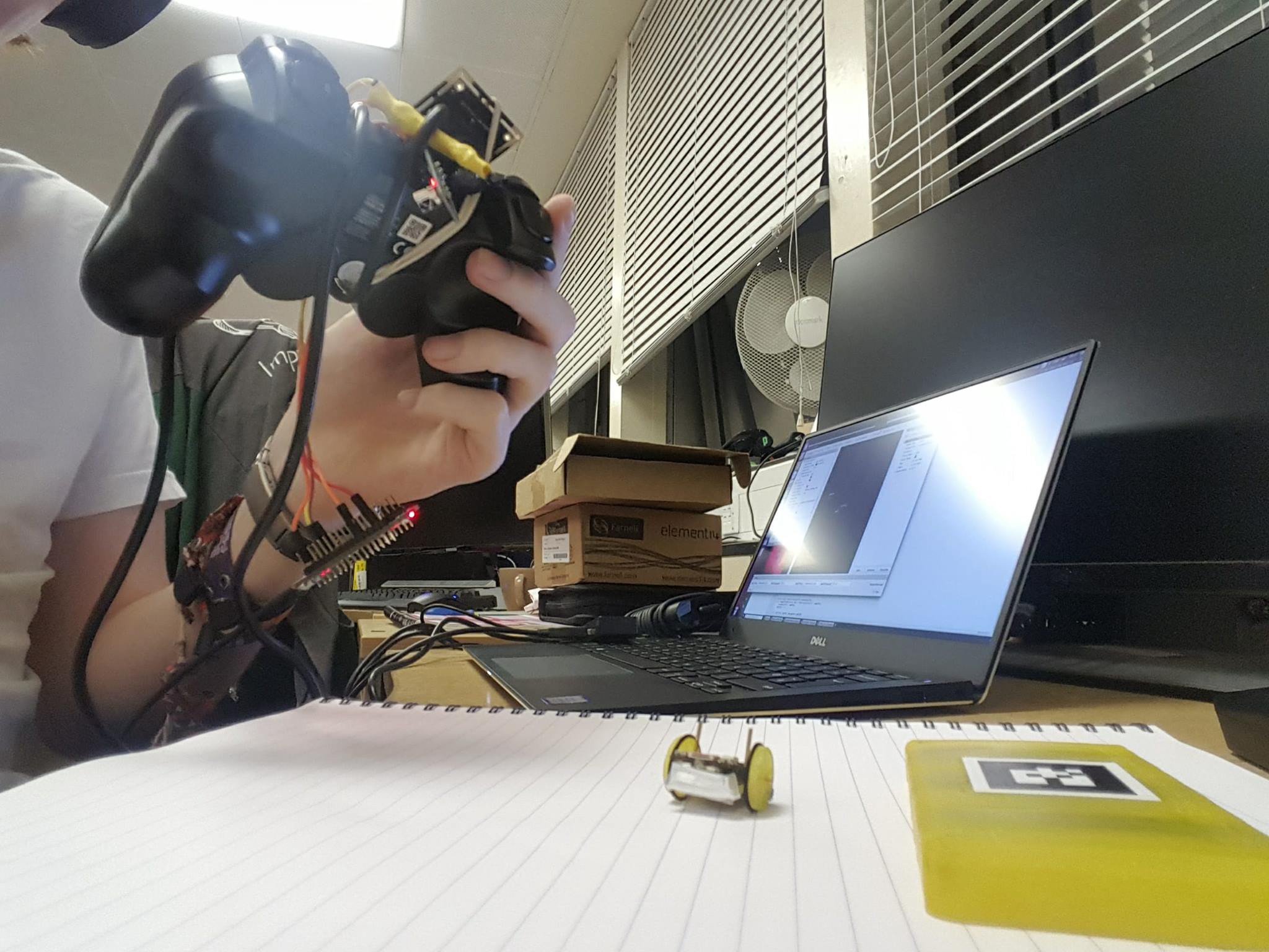
Whilst the robots do have a few local sensors, for collision avoidance and line following/boundry detection, their main location sensing will be provided by an overhead camera and transmitted over IR to the robots. Using this in combination with the tiny stepper motor odometry, complicated trajectories are possible.
So please LIKE and FOLLOW this project if you are interested, we will soon have more tech demos posted and we wouldn't like you to all miss out!
(Early releases, not recommended for those who prefer code that operates, and boards that are free of bugs ;) )
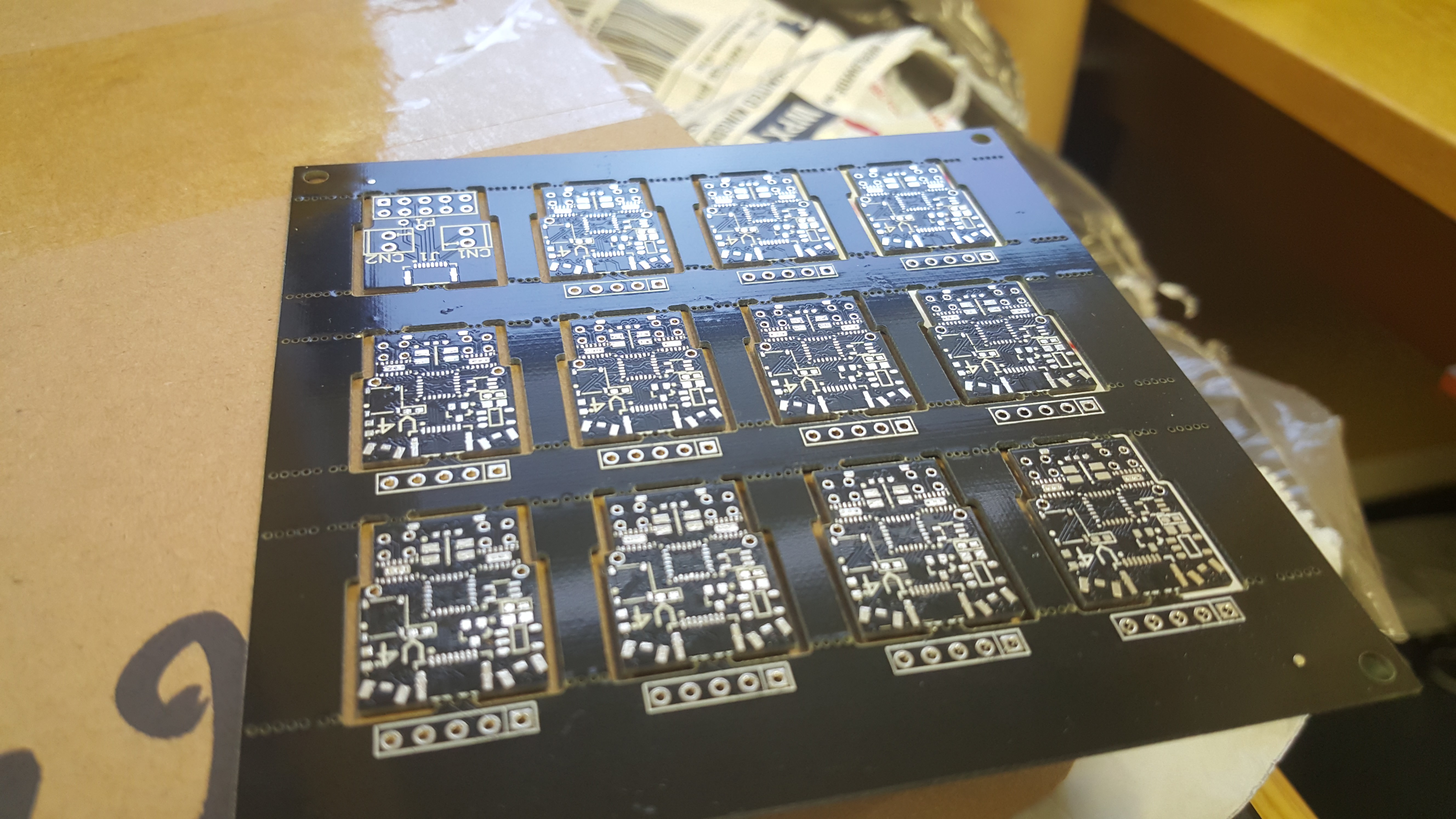
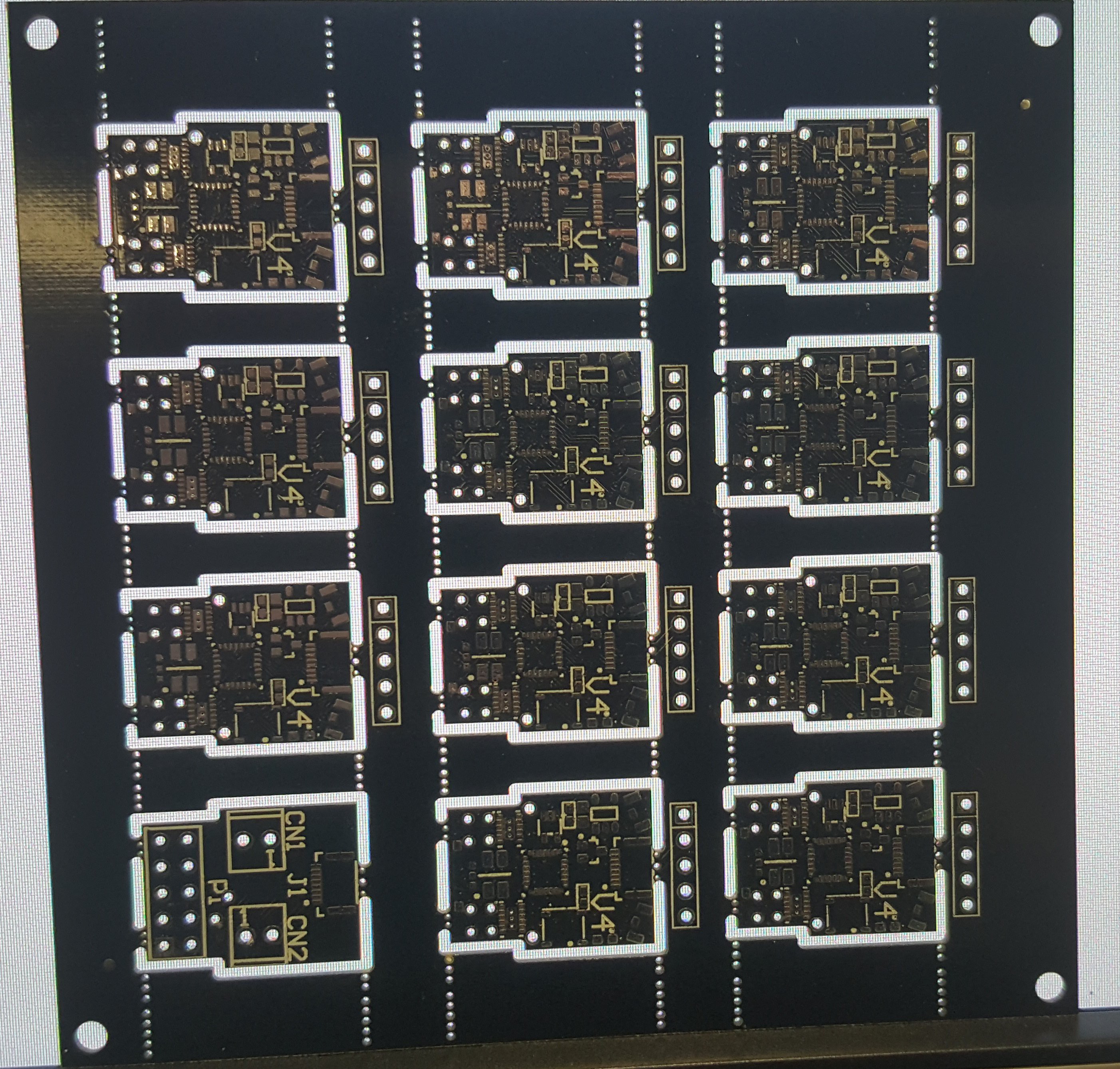
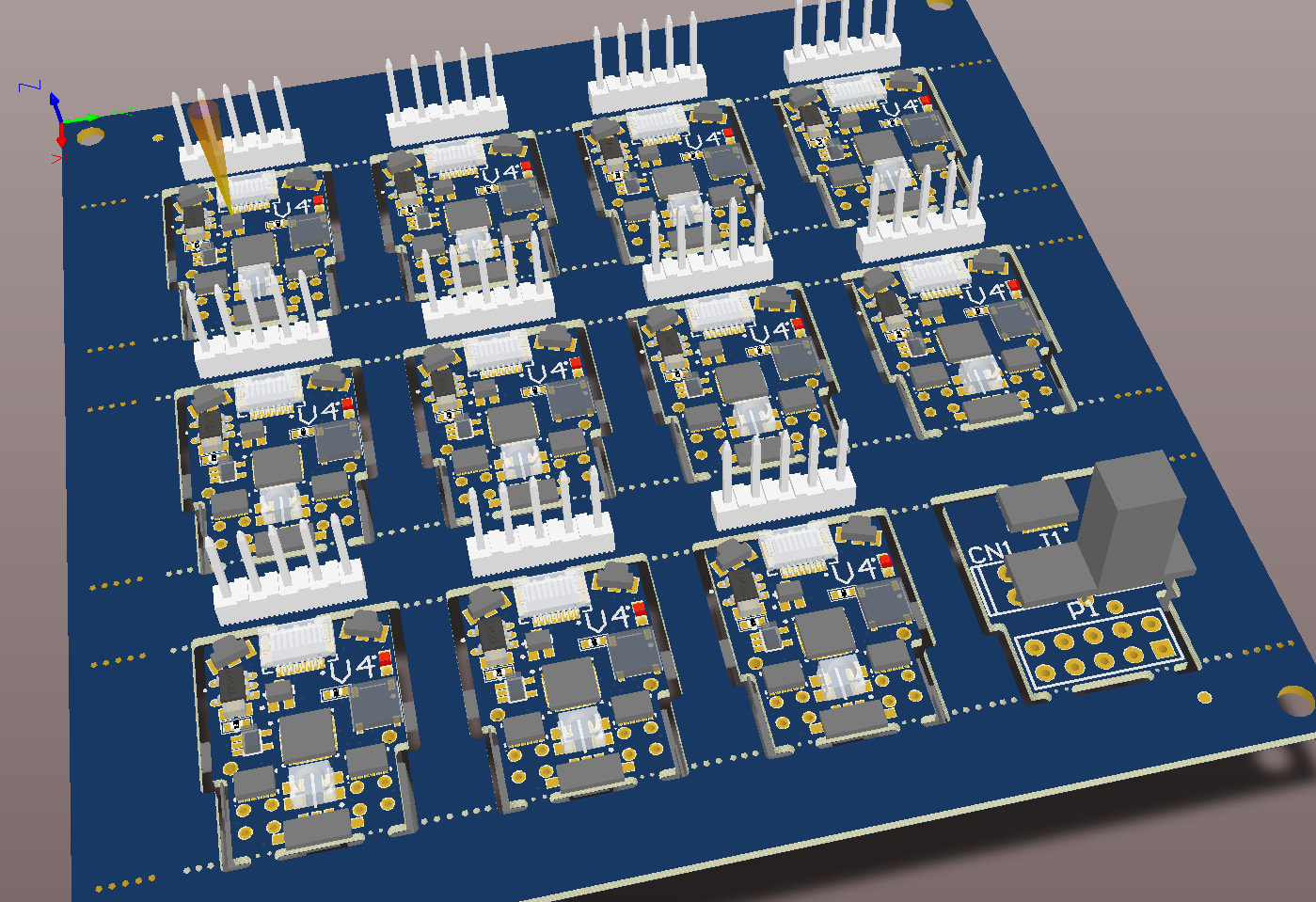
PCB source. Shared under Attribution-ShareAlike 4.0 International (CC BY-SA 4.0) .
Software source. Shared under GNU General Public License V3.0 .
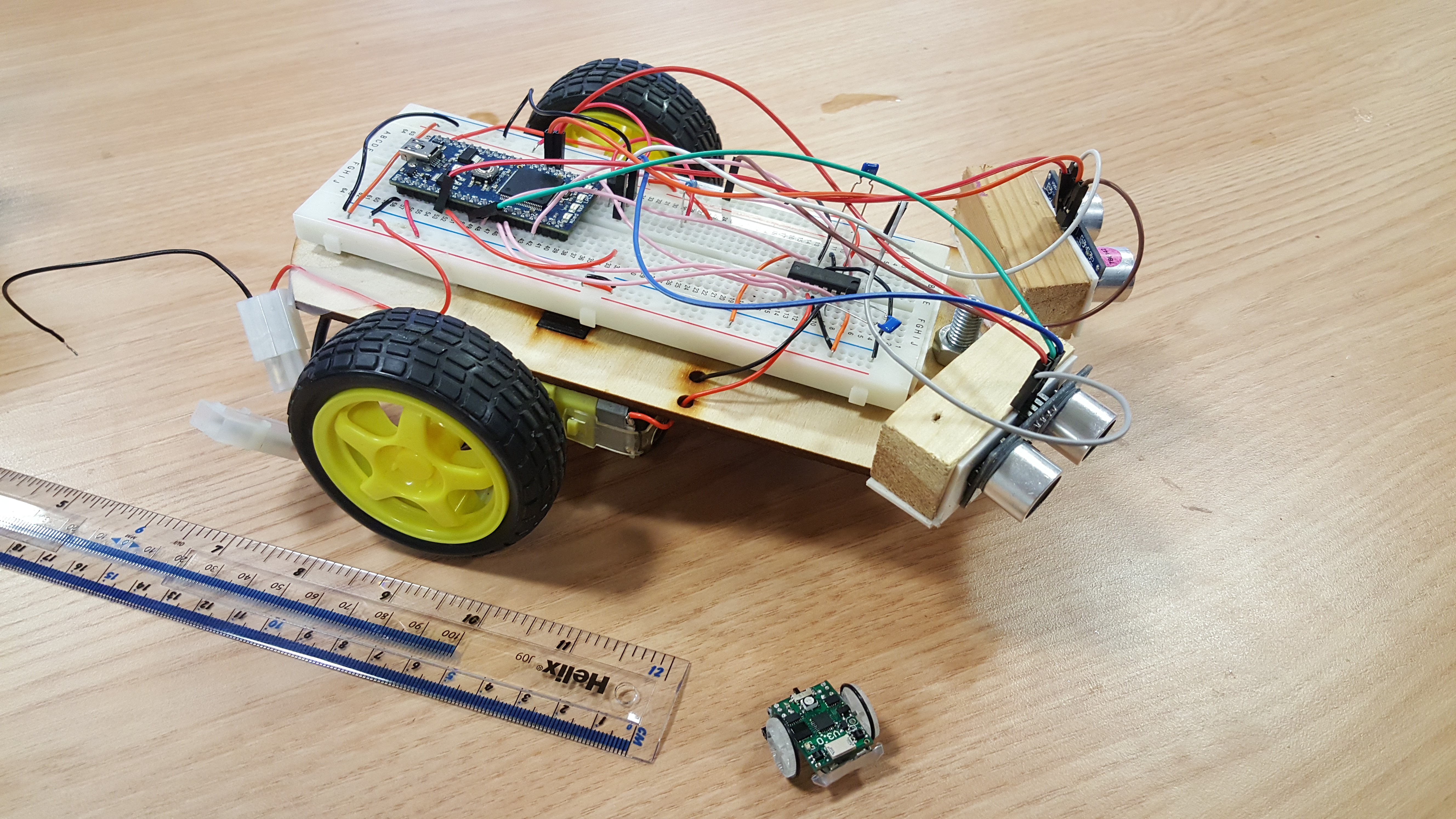
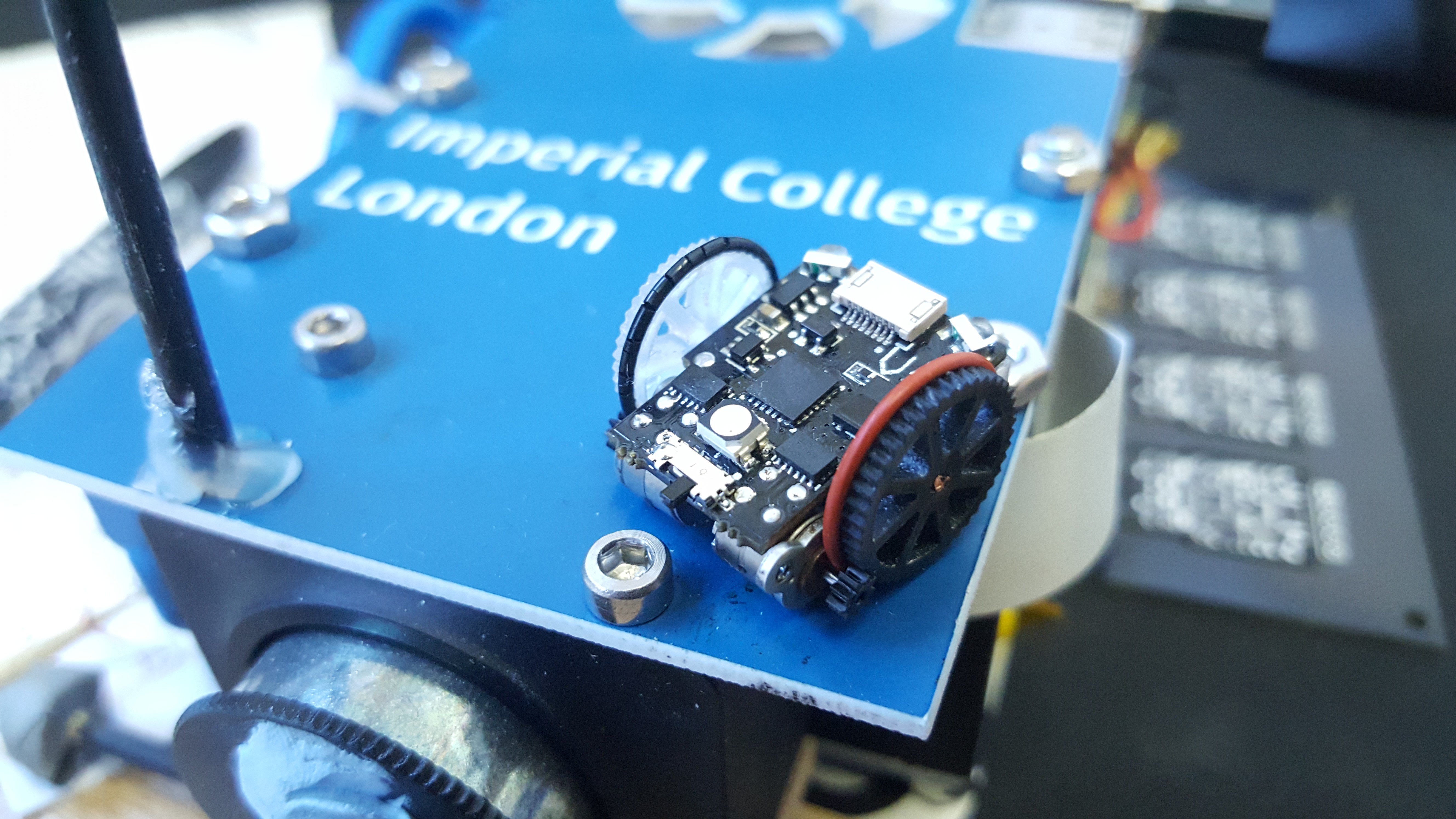
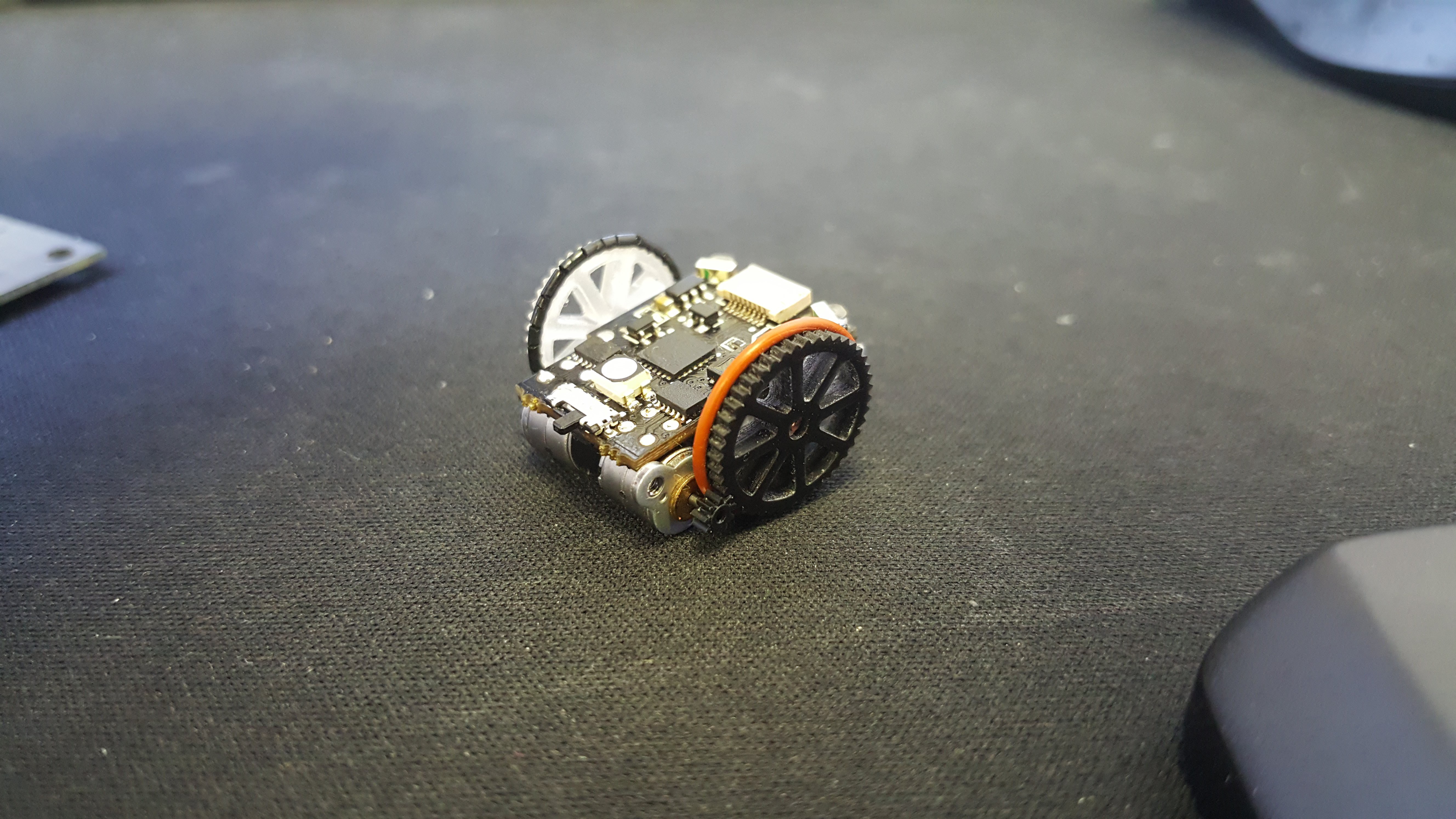
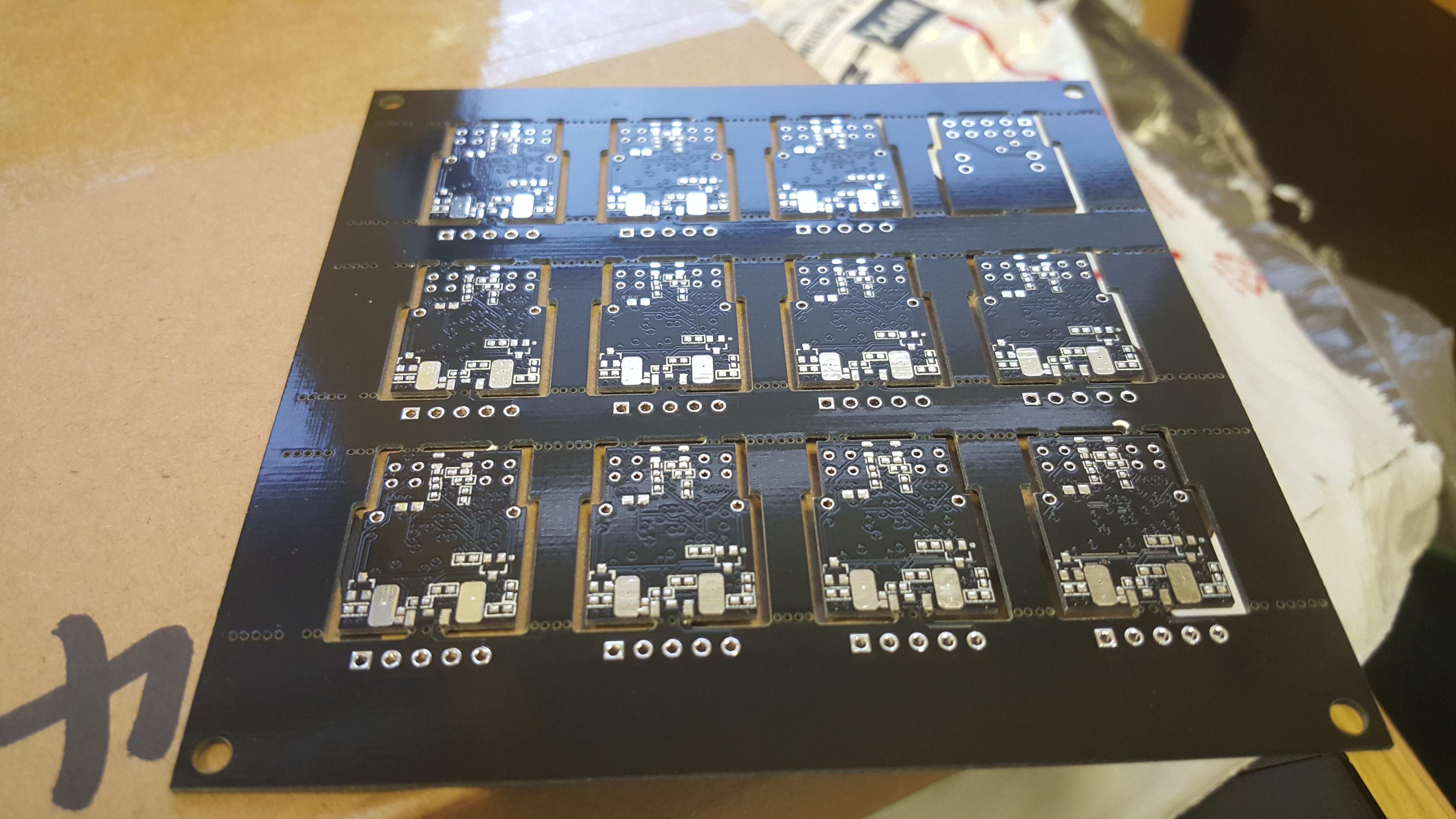
Did we mention these things are small!
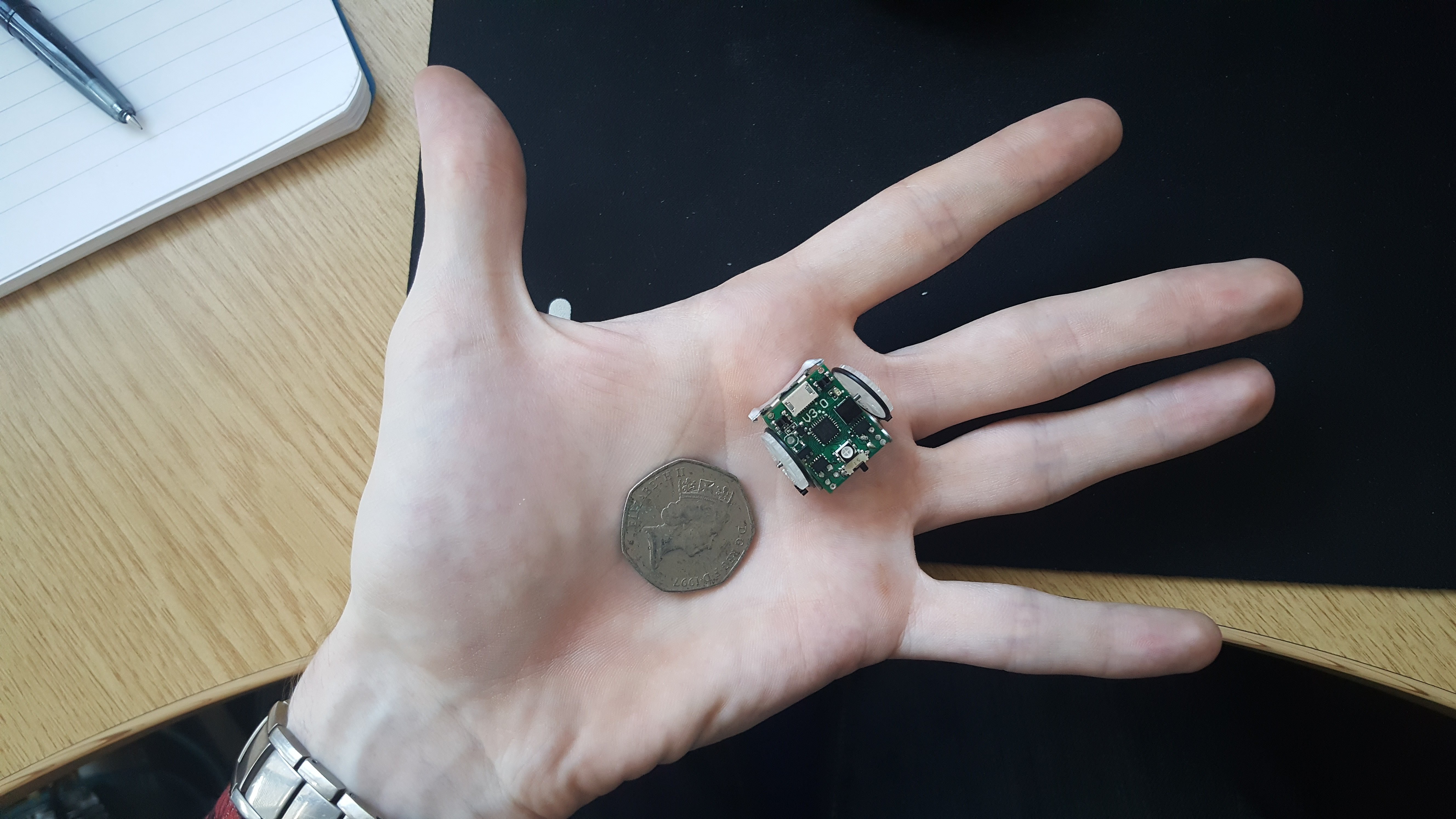
Compared to a typical 'educational robot'.
PS: If you are interested in tiny robots, I imagine that you would think large, high speed robots are cool too. Check out Oskar Weigl's project over at https://hackaday.io/project/11583-odrive-high-performance-motor-control . Low cost, devastatingly powerful servo motors can be yours!
PPS: If you are interested in the other things I am up to, you can visit my website.


 Kenny.Industries
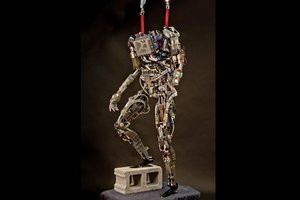
 Shifty
 witchdoc
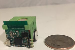
 Bill Weiler
Seem to me, it is a great step in future. Robots which help to study - I feel jealousy for a new generation. It was ironic, by the way. Cause, when I was a young learner I had a hobby to complete robots. But didn`t have enough time to study. If I know one of recourse https://www.essaypaper.review/top10-essay-services-reviews/ I`d rather drop into science and don`t have a mind about homework and will become a mechanical engineer. Some review examples are available even they have been rated with the top 10.