 Joshua Elsdon
Hello! This is another dejavu post. We have already presented a system that used a camera system to located the robots. Since then I have gone to a large robotics conference (for an unrelated project), I took the micro robots with me and they were a minor hit amongst the people that I had impromptu demo with. The lesson learned from this trip was that any demo of the project should be portable and quick to set up. Therefore a carefully calibrated system with controlled lighting and a mount for the camera is a nono!
In the future I hope to integrate the following onto a single board computer of some kind, minimising the amount of trailing wires and inconvenience. Any way without further ado, what have I built/
Firstly with a free moving camera there is no simple way to use it as a reference as with our old implementation. Therefore we need to put a reference in the environment. In our case a small QR code. This QR code now can represent (0,0,0) for the robots. Luckily ROS has a very capable package for this task ar_track_alvar . This package provides the transform between the camera and all QR codes that are visible in the scene. Easy as pi eh?
Next we need to find the robots in the camera image. The easy way would be to put QR codes onto the robots, however they are too small. Also this would make each robot unique, which is awkward when you want to make 100s of them. Therefore we are going to have to do it using good ol'fashioned computer vision. For this I used the OpenCV library. The library is packaged with ROS also, using some helper packages, things work smoothly.
The actual algorithm for finding the robots is not too complicated. We threshold the incoming image to find the LED and the front connector that has been painted red with nail polish. These thresholded images are then used as an input to a blob detector. The outcome is we should have a number of candidates for LEDs and front connectors.
Next we need to pair them up. To do this I project all of the points from camera space to the XY plane defined by the QR code. This gives us the 'true' 3D position of these features, as I make sure that the real QR code is at the same level as the robots top surface.
Now for each potential LED we have found we search all potential front connectors, if the distance between the features is the same as they are in real life (13.7mm) then we can say this is very likely a robot.
Next we do a check to ensure our naming of the robots is consistent with what they were in the previous iteration. This is simply associating the potential robot with the actual robot that is closest to it (based on where it was last time and the accumulated instructions sent to the robot).
Finally we convert the positions of the LED and front connector to a coordinate system that is centred on the centre of the wheel base. This is then published to the ROS system.
The outcome is that ROS has a consistent transform available for each of the robots in the system, as a bonus we also have the position of the camera in the same coordinate system. This means we could make the robots face the user, or have their controls always be aligned with the user position. (RC control is very hard when the vehicle is coming towards you, this could be a good remedy.)
A long wordy post is not much without a video, so hear you go:
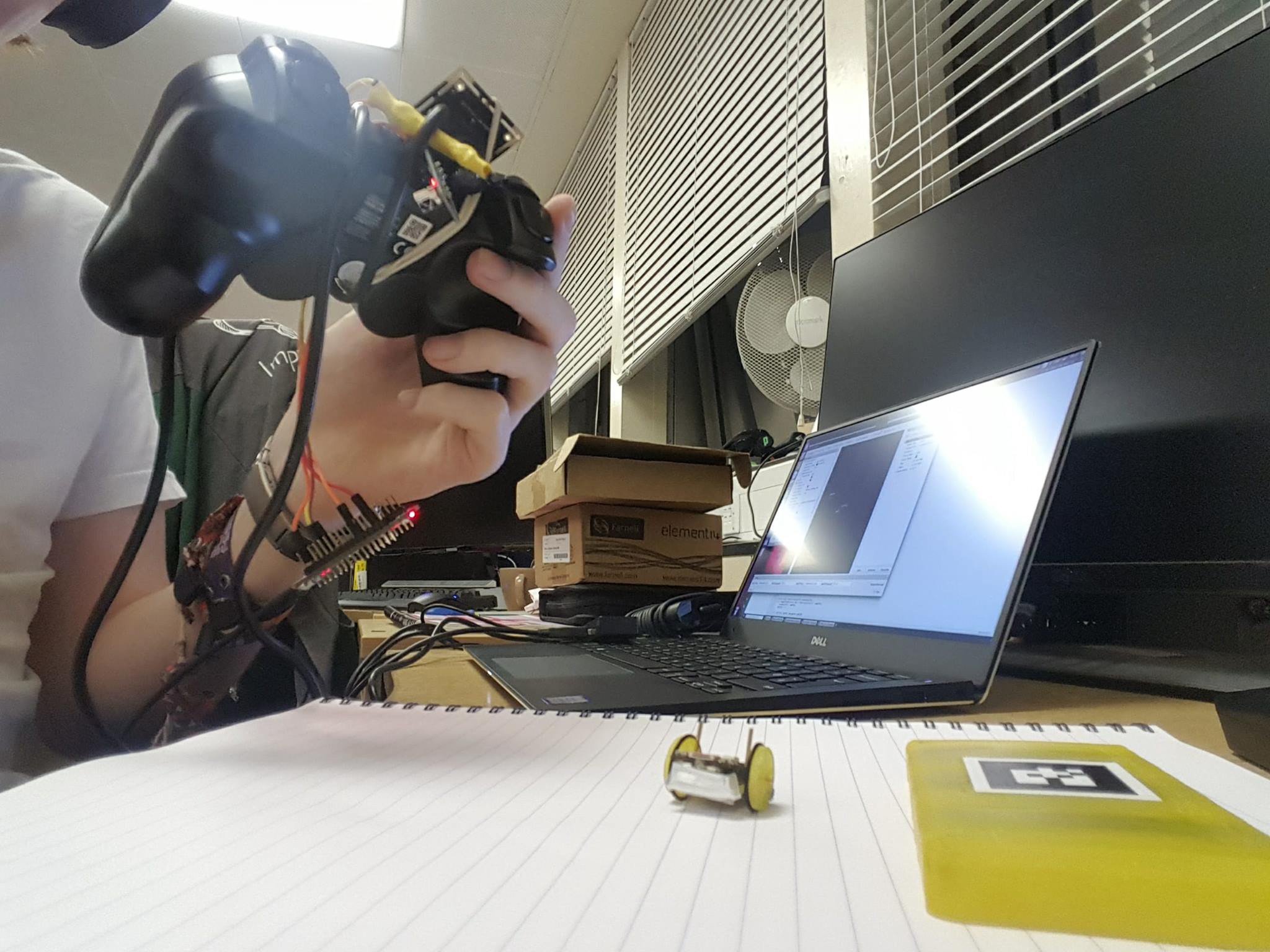
Here is a picture of the very awkward setup as it stands:
Discussions
Become a Hackaday.io Member
Create an account to leave a comment. Already have an account? Log In.