 Joe Mendia
After clearing the idea of OLI and in order to proof the concept I designed the first base board to be used to test the modular design behind the OLI.
Here is the first board with the power circuitry soldered by hand.
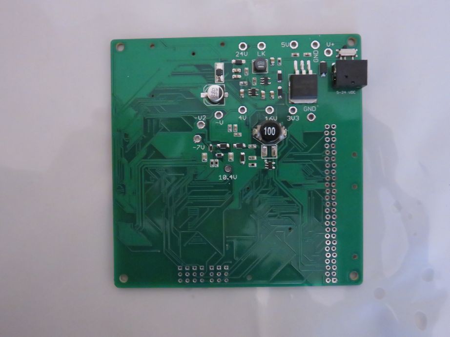
This board was made in order to generate the different voltages (3.3V, 4V, 10.4V, 16V, 24V and -7V) needed by the 7" LCD and to break the 24 RGB signal to a connector to attach the video modules.
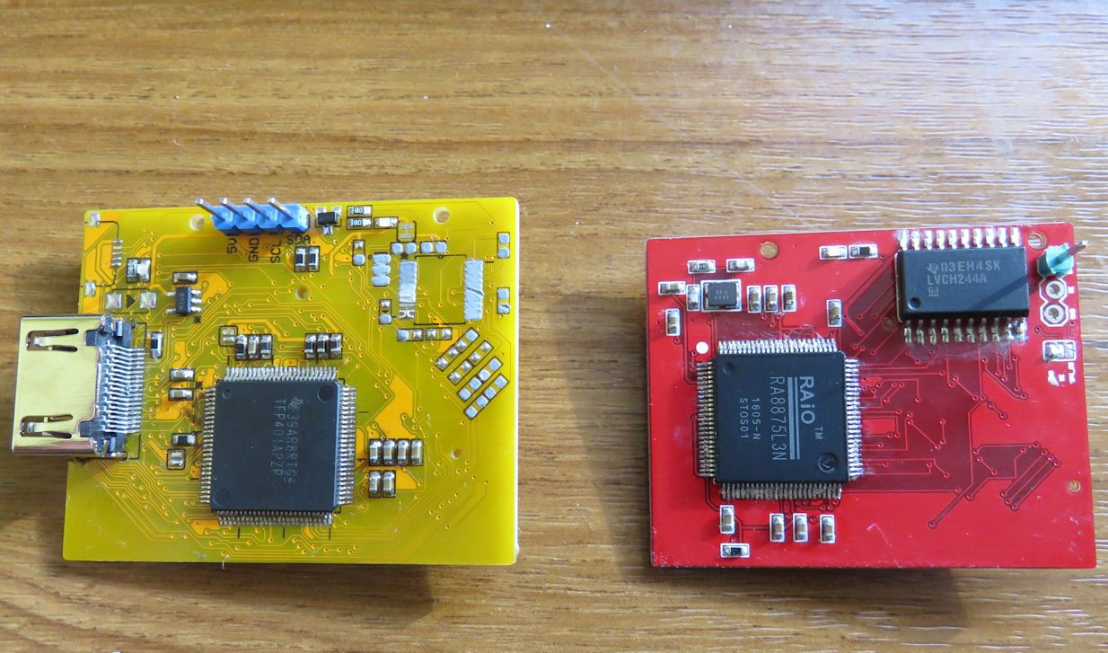
For the video signals, two PCBs were also made, the yellow one is a HDMI decoder based on the TFP401A and the red one is based on the RA8875.
The test of the yellow one with the base board can be seen here:
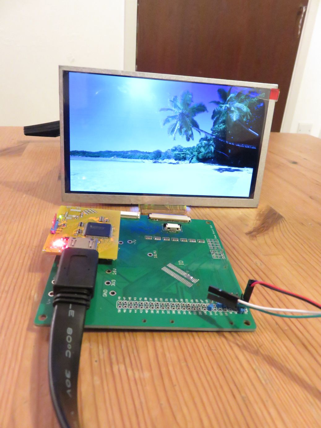
The HDMI signal is from my laptop showing an image, the quality is quite good. Based on this tests I have concluded that the concept is feasible and will have to refine the base board design.
Here you can see a video testing the 5" LCD with a HD Video from youtube. The 40p connector to the LCD in the main board has a fault and the colors are not nice so I have connected it to the 50p interface of the base board and it works great.
Discussions
Become a Hackaday.io Member
Create an account to leave a comment. Already have an account? Log In.