 Caleb Peters
First and foremost, this is a challenge build. There are much better ways to go about building a DIY CNC router. I contemplated buying a Shapeoko 3, but decided that building my own could prove an interesting opportunity to grow my knowledge and skills.
Project goals:
- Meet, or exceed the performance of a stock Shapeoko 3.
- Can’t exceed the price of the Shapeoko 3.
- ???
- Profit.
Important Tools:
- Old benchtop mill (I think it’s called a Bench Master)
- X-carve CNC router
To do list:
- Make a to do list (Nailed it!)
- Make a BOM
- Build three linear motion rails similar to the SO3 specs. (Done)
- Design and mill motor mount and end plates. (Done)
- Design and build a z-axis. (Done)
- Build a flat and level table for the machine to mount to. (Done)
- Assemble the mechanical components. (Done)
- Wiring (what a nebulous term, but done!)
- Calibrate and test performance.
- Create a fusion 360 file for the entire build.
- Add to the to do list.
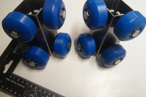
 Like all Shapeokos this machine is going to use GT2 belts on the X and Y axis. I chose to go with the slightly beefier 9 mm variant which I believe is what the Shapeoko 3's are using now as well. 9 mm belts look deceptively bigger than 6 mm belts until you put them right on top of each other. it would be interesting to know just what kind of a performance increase there really is between the two sizes. However, I've a tendency to think that this is about as big of a machine as I would want to use belts to drive, but then again I haven't seen a spec sheet outlining how much weight these belts can actually handle. Although, this is just a gut feeling on my part.
 Unlike the Shapeoko 3 I've planned a slightly more traditional screw driven z-axis design. I'm using some of open builds' "Tr8*8-2p" lead screw, and Anti-Backlash Nut Block to accomplish this. I'm relying heavily on experience I gained from building my own custom z-axis for my X-carve.
 I picked up some inexpensive hall effect sensors from Amazon. I'm hoping these will work out, but there's no real guarantee that they will. If they do, then at least I'll be able to recommend them unlike the ones I use on my X-carve
 Finally, I've chosen to use a Porter-Cable 450 router as my spindle. I've ripped off all the electronics in preparation to set it up with my superPID. I also picked up one of the 1/8" elaire collet for it. Side note, the elaire collet looks really nice! I've also picked up a DWP 611 mount from inventables. I really like how it's built, but I do have some misgivings on whether or not it will allow for enough z-axis reach. If it doesn't, its not really a huge deal. I designed the z-axis to accommodate the Shapeoko 2/X carve spindle mounting plate dimensions, so I got plenty of options available.


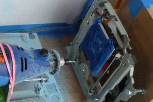
 As I said earlier, I've done quite a bit of aluminum milling on my X-carve. In the past I've exclusively used a 1/8" carbide single flute bit. However, in the case of this project, I decided to try out one of destiny tool's 1/8" Viper end mill. I'm not going to hold you in suspense, it was a great decision! These little things rock for one reason or another. To go over its specs, it's a high helix 1/8" three flute carbide end mill with a coat they refer to as "stealth." When milling aluminum in the past, I've always used WD-40 or some sort of cutting oil. Although, I found that this end mill worked exceptionally well when I stopped using cutting oil and just placed the vacuum nozzle close to where the bit was milling. But, enough of me gushing about the fancy end mill.
 It only took two hours to mill out all four plates, and I have to say I think they turned out quite nice. Fitting the plates onto the ends of the two y-axis rails was a pretty good test of whether or not I placed the threaded holes at the ends of the rails accurately, and at least for now it looks good enough to work.
 morph
morph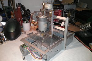
 Stefan Lochbrunner
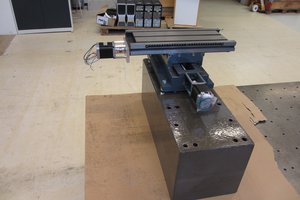
 Paul McClay
Good afternoon Caleb, you've done an incredible job on this build. I'm super impressed. I have the big X-Carve but now I want to build a large plasma/router (switch-able) machine with the capability of taking a 4x8 sheet of plywood/steel. What did your max Z travel work out to? And what can I offer you for your Aspire project files?