0%
0%
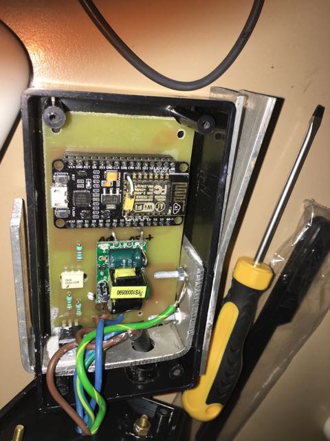
Electric Water Heater controler
To Control an electric water heater to only use the surplus power from my 3KW PV array
 Saabman
Become a Hackaday.io member
Already have an account? Log in.
Just one more thing
To make the experience fit your profile, pick a username and tell us what interests you.
Pick an awesome username
hackaday.io/
Your profile's URL: hackaday.io/username. Max 25 alphanumeric characters.
Pick a few interests
Projects that share your interests
People that share your interests

 MCenderdragon
 Ted Yapo
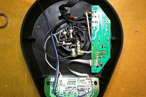
 luma
luma
 Moritz Walter